
- 1.0Introduction: The Importance of Machinery Safety
- 2.0What is ISO 13849?
- 3.0Core Concepts Explained
- 4.0How is Performance Level (PL) Determined?
- 5.0ISO 13849-1 vs. IEC 62061 Comparison
- 6.0Key Revisions in ISO 13849-1:2023
- 7.0Implementation Recommendations & Best Practices
- 8.0Major Controversies and Criticisms of ISO 13849-1:2023
- 9.0Resource – EN ISO 13849 (PDF) Machinery Control Functional Safety Standard
1.0Introduction: The Importance of Machinery Safety
In industrial automation, machinery safety is vital for protecting lives, ensuring system stability, and meeting legal requirements. ISO 13849 offers global guidance for designing and verifying safety-related parts of control systems (SRP/CS), forming a key technical foundation for safety in mechanical manufacturing.
2.0What is ISO 13849?
ISO 13849 is a functional safety standard focused on the design of safety-related parts of machinery control systems. It consists of two parts:
- ISO 13849-1:2023, Part 1: General principles for design, safety requirements, and guidance for integrating SRP/CS.
- ISO 13849-2, Part 2: Validation, which provides methods to analyze or test safety functions and confirm the achieved Performance Level (PL).
ISO 13849 is a risk-based standard. It defines which safety functions are necessary based on risk assessment and specifies the Performance Levels they must achieve to reduce risk to acceptable levels. This standard applies to a wide range of machinery, including press brakes, stamping machines, decoilers, feeding lines, injection molding machines, packaging equipment, and cutting machines.
2.1What’s New in ISO 13849-1:2023
The 2023 revision improves both structure and clarity, making implementation more intuitive. Key changes include:
- Terminology update: Replaces SRP/CS with the term “subsystem” throughout the standard for consistency and clarity.
- Improved safety function definitions: Clarifies the structure and content of safety functions and Safety Requirements Specifications (SRS).
- Enhanced Category 2 guidance: Provides more detailed guidance on architecture and fault handling for Category 2 systems.
- Integrated validation process: Combines design and validation into one standard by incorporating procedures formerly in ISO 13849-2.
- Stronger focus on reliability factors: Increases emphasis on Common Cause Failure (CCF), software reliability, and EMC immunity.
- Expanded annexes with practical examples: Adds real-world guidance, including software validation (Annex N) and EMC countermeasures (Annex L).
3.0Core Concepts Explained
SRP/CS: Safety-Related Parts of Control Systems
Performance Level (PL): Safety performance levels ranging from PL a to PL e
Required Performance Level (PLr): The PL required, determined by risk assessment
Key Parameters:
- Category(system architecture classification)
- MTTFd(Mean Time To Dangerous Failure)
- DCavg(Average Diagnostic Coverage)
- CCF(Common Cause Failure resistance)
- Software Safety Requirement
4.0How is Performance Level (PL) Determined?
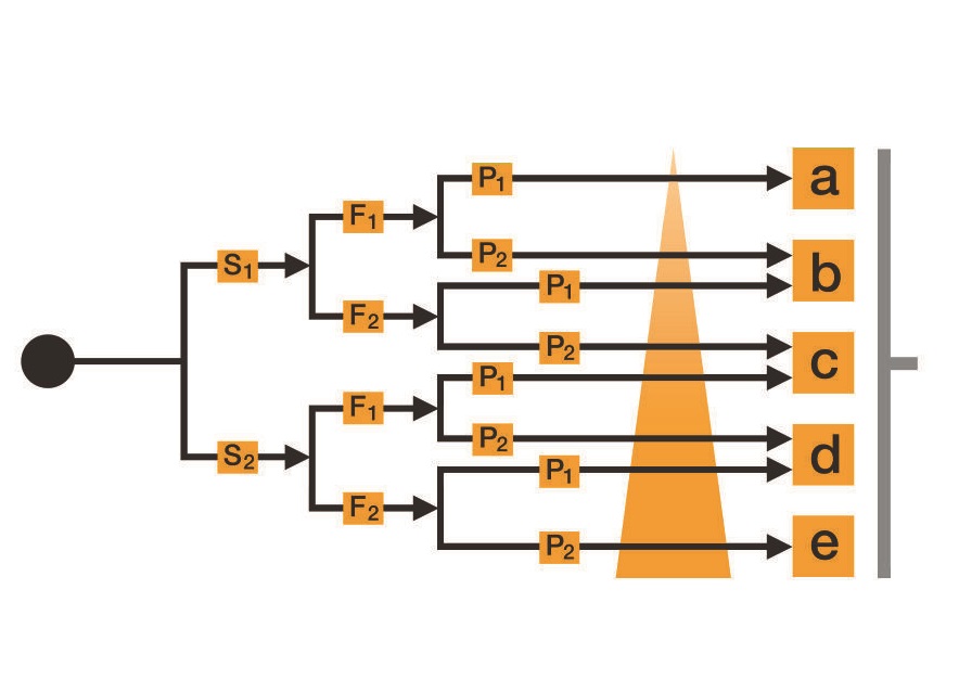
4.1Graph-Based Risk Assessment (According to EN ISO 13849-1)
Risks are assessed in EN ISO 13849-1 using a risk graph. The evaluation is based on the following three criteria:
- Severity of Injury (S)
- Frequency and/or Exposure to the Hazard (F)
- Possibility of Avoiding the Hazard or Limiting the Harm (P)
The result of this assessment is the required Performance Level (PLr) for each individual safety function, which is intended to minimize the identified risks.
- PL a corresponds to a low level of risk,
- PL e corresponds to a high level of risk.
4.2Risk Parameters
S – Severity of Injury
- S1 = Slight (normally reversible injury)
- S2 = Serious (normally irreversible injury or death)
F – Frequency and/or Exposure to Hazard
- F1 = Seldom to less often and/or exposure time is short
- F2 = Frequent to continuous and/or exposure time is long
P – Possibility of Avoiding the Hazard or Limiting the Harm
- P1 = Possible under specific conditions
- P2 = Scarcely possible
4.3Factors Influencing Parameter P (Avoidance Possibility)
The possibility of avoiding or limiting the hazard (P) is influenced by the following five factors:
- The speed at which the hazard arises (e.g. quickly or slowly)
- Physical possibilities for avoiding the hazard (e.g. by escaping)
- Practical safety experience relating to the process or operation
- Whether the operation is conducted by experts or non-professionals
- Whether the operation is performed with or without supervision
| Determination of parameter P – Factors | A | B | C |
| Machine is used by | Specialist | Layperson | |
| Speed of the part of the machine that can cause a hazardous event | Event at low or very low speed | Event at medium speed | Event at high speed |
| Physical possibility of avoiding the hazard | Possible in at least 50 % of cases | Possible in less than 50 % of cases | Impossible |
| Possibility of recognising/sensing the hazard | Possible in at least 50 % of cases | Only possible in less than 50 % of cases | Impossible |
| Complexity of the operations | Low complexity or no interaction | Medium to high complexity |
If “C” is selected OR “B” is selected at least three times: P2
If “C” is not selected AND “B” is selected twice: P1 or P2, depending on the specific situation
If “C” is not selected AND “B” is zero or selected once: P1
Example: For a safety interlock function on a stamping or packaging machine, analyze the operating principle, identify the required PLr (e.g., PL d), and ensure the system achieves this level through inputs like MTTFd and DCavg.
5.0ISO 13849-1 vs. IEC 62061 Comparison
| Aspect | ISO 13849-1 | IEC 62061 |
| Approach | Categories + Performance Levels (PL) | SIL (Safety Integrity Level) |
| Applicable To | Machinery | Complex automated systems |
| Complexity | Relatively simple | Useful for in-depth system analysis |
| Integration | Structure, timing, diagnostic coverage | Probability of successful function, response time |
6.0Key Revisions in ISO 13849-1:2023
Clearer definitions, replacing “SRP/CS” with “subsystem” terminology
Enhanced standardization of safety requirements
Optimized definition for Category 2, with stronger emphasis on CCF
Improved software safety guidance (Chapter 7)
Integration of some validation content from ISO 13849-2 into Part 1
Extended annexes: CCF (Annex F), EMC (Annex L), Safety Requirements Specification (SRS, Annex M), software validation examples (Annex N)
7.0Implementation Recommendations & Best Practices
For high-cycle automated machinery such as unwinders, press brakes, feeding devices, and laser cutting equipment, it is recommended to embed ISO 13849 principles at the design stage to ensure personnel safety and regulatory compliance:
Consider safety functions from the initial control system design phase
Avoid over-reliance on single-point controllers; ensure strong hardware/software cooperation
Maintain thorough and consistent technical documentation to demonstrate compliance
Utilize practical tools like SISTEMA for structural safety analysis
8.0Major Controversies and Criticisms of ISO 13849-1:2023
Although the 2023 revision improves structure and applicability, several industry concerns remain:
- Potential safety reductions due to unproven technical methods
- Design requirements for safety-related embedded software (SRESW) exceeding scope; these belong to IEC 61508-3:2010
- Standard PLCs lacking redundancy and diagnostic capabilities for high PL (PL c and above)
- “No data” PL evaluation approach lacking scientific basis
- EMI immunity evaluation methods in Annex L (Route C) may insufficiently guarantee robustness
- Incomplete standard transition causing implementation confusion
9.0Resource – EN ISO 13849 (PDF) Machinery Control Functional Safety Standard
ISO 13849-1:2023 official standard download (EN ISO version)
ISO 13849-1:2012 official standard download (EN ISO version)
VDMA 66413 VDMA Specification standard download
References
https://www.pilz.com/en-US/support/law-standards-norms/functional-safety/en-iso-13849-1
https://www.iso.org/standard/73481.html
https://knowledge.bsigroup.com/products/safety-of-machinery-safety-related-parts-of-control-systems-general-principles-for-design-5