
- 1.0Why Should You Understand ASME Y14.5?
- 2.0What Is ASME Y14.5?
- 3.0In-Depth Look at GD&T Core Concepts
- 4.0Common GD&T Symbols: Categories and Definitions
- 5.0Why Use GD&T Instead of Traditional ± Dimensions?
- 6.0Key Updates in ASME Y14.5-2018
- 7.0ASME vs. ISO GD&T Standards (Quick Comparison)
- 8.0Conclusion: Why ASME Y14.5 Matters
- 9.0Frequently Asked Questions (FAQ)
- 10.0Recommended Resources
1.0Why Should You Understand ASME Y14.5?
In modern manufacturing and design collaboration, engineering drawings convey more than just dimensions—they represent a geometric language. While traditional ± tolerances are widely used, they often fall short when describing complex geometric relationships and assembly requirements. This is where ASME Y14.5 becomes essential.
ASME Y14.5 is the Geometric Dimensioning and Tolerancing (GD&T) standard published by the American Society of Mechanical Engineers (ASME). It is widely applied across mechanical design, manufacturing, and quality inspection. The standard provides a unified language and set of rules for defining geometric features, tolerance requirements, and datum references for parts.
2.0What Is ASME Y14.5?
ASME Y14.5 is the authoritative standard for GD&T. It defines the symbols, terms, notation methods, and application principles used in engineering drawings. The standard is widely adopted in high-precision industries such as aerospace, automotive, mold making, and equipment manufacturing.
2.1Purpose of the Standard
- Enhance technical communication: A globally recognized system of symbols reduces misinterpretation.
- Clearly express design intent: Focuses on function, not just numerical dimensions.
- Reduce rework and misunderstandings in manufacturing:Functional tolerance definitions help improve conformity rates.
2.2Brief History of ASME Y14.5
| Year | Version | Key Features |
| 1949 | ASA Y14.5-1949 | First edition; established basic dimensioning principles. |
| 1966 | USASI Y14.5-1966 | Introduced the concept of positional tolerances. |
| 1982 | ANSI Y14.5M-1982 | Introduced feature control frames; adopted metric units. |
| 1994 | ASME Y14.5M-1994 | Expanded concepts like MMC/LMC. |
| 2009 | ASME Y14.5-2009 | Strengthened functional dimensioning; aligned more with ISO. |
| 2018 | ASME Y14.5-2018 | Latest revision; supports MBD, removed certain symbols. |
Since 2009, the “M” suffix was dropped, making the standard applicable to both inch and metric units.
2.3Core Structure of ASME Y14.5
Key elements covered in ASME Y14.5 include:
- Terms and Definitions: Establish a common language for GD&T
- GD&T Symbol System: Used to control form, orientation, location, and runout
- Feature Control Frame (FCF): Standard format for communicating tolerance information
- Datum Rules: Define functional datums and build the Datum Reference Frame (DRF)
- Modifiers: Such as MMC (Maximum Material Condition), LMC (Least Material Condition), and RFS (Regardless of Feature Size), used to refine tolerance behavior
- Drawing and Model Annotation Methods: Covers both 2D drawing practices and Model-Based Definition (MBD)
3.0In-Depth Look at GD&T Core Concepts
3.1What Is GD&T (Geometric Dimensioning and Tolerancing)?
GD&T is a function-oriented system for defining and communicating part geometry. It describes shape, orientation, location, and variation more effectively than traditional ± tolerancing, particularly for 3D assemblies.
Example:
Instead of applying ±0.05 mm tolerances separately to the X and Y axes to control hole location, GD&T can specify that the hole must fall within a 0.1 mm diameter tolerance zone—more accurate and easier to interpret.
3.2Datum and Datum Features
Datums are reference surfaces, lines, or points used during inspection, assembly, or manufacturing. ASME Y14.5 requires the creation of a Datum Reference Frame (DRF), structured in a primary → secondary → tertiary hierarchy to ensure consistent part orientation and measurement.
3.3Feature Control Frame (FCF)
The Feature Control Frame is the fundamental structure in GD&T for expressing tolerance requirements. It includes:
- Geometric Characteristic Symbol(e.g., ⬚ for flatness, ⊕ for position)
- Tolerance Value and Zone
- Datum References in Specified Order(e.g., A-B-C)
Example:
⊕ | 0.1 | A | B | C
This indicates that the feature’s position must be controlled within a 0.1 mm zone relative to datums A, B, and C.
4.0Common GD&T Symbols: Categories and Definitions
4.1Form Controls
| Feature | Symbol | Description |
| Flatness | ⬚ | Controls how flat a surface must be |
| Straightness | ⬒ | Ensures a feature lies in a straight line |
| Roundness | ◎ | Controls the circularity of a cross-sectional view |
| Cylindricity | ⌭ | Controls the overall geometry of a cylindrical feature |
4.2Orientation Controls
| Feature | Symbol | Description |
| Parallelism | ∥ | Maintains parallel alignment to a datum |
| Perpendicularity | ⊥ | Ensures right-angle orientation to a datum |
| Angularity | ∠ | Maintains a specific angle relative to a datum |
4.3Location Controls
| Feature | Symbol | Description |
| Position | ⊕ | Precisely locates the center of a feature |
| Concentricity | ◎ with composite datums | Aligns axes of features to a common centerline |
4.4Runout Controls
| Feature | Symbol | Description |
| Circular Runout | ⌰ | Controls variation in a single circular cross-section |
| Total Runout | ⌰ (with arrow) | Controls variation across the entire rotating surface |
4.5Profile Controls
| Feature | Symbol | Description |
| Profile | ⌒ | Controls the precision of complex curves and surfaces |
5.0Why Use GD&T Instead of Traditional ± Dimensions?
Traditional ± dimensions apply limits only in the X and Y directions, which can lead to ambiguity. GD&T, on the other hand, governs the entire geometry, allowing tolerances to be more uniformly distributed—better reflecting real-world assembly conditions.
5.1Example: Assembly Accuracy in Aerospace
In aerospace applications, positional tolerancing is commonly used to precisely control rivet hole alignment between mating sections. This minimizes cumulative error and reduces the need for manual adjustment during assembly.
6.0Key Updates in ASME Y14.5-2018
- Removed concentricity and symmetry symbols (now handled through position tolerances)
- Unequal profile tolerances are now indicated using a unified “U” modifier
- Shift from size-based to feature-based tolerance principles
- Terminology update: “Datum Feature Simulator” reverted to “Actual Mating Envelope”
- Expanded support for Model-Based Definition (MBD)
- MMC/LMC explanations refined to better reflect surface-based measurements
7.0ASME vs. ISO GD&T Standards (Quick Comparison)
ASME Y14.5 and ISO 1101/ ISO 286 are the two main GD&T standards used worldwide. Here’s a quick comparison to highlight their key differences.
| Criteria | ASME Y14.5 | ISO 1101 / ISO 286 |
| Origin | U.S. (ASME) | International (ISO) |
| Primary Regions | North America, global use | Europe and Asia |
| Focus | Functionality & assembly alignment | General consistency & flexibility |
| Common Industries | Aerospace, automotive, mold, defense | Automotive, general manufacturing, export sectors |
| Symbol System | More intuitive | Symbol-rich and structurally flexible |
8.0Conclusion: Why ASME Y14.5 Matters
ASME Y14.5 is more than just a drawing standard—it’s a universal technical language that connects design, manufacturing, and inspection. Mastering GD&T allows you to:
- Clearly communicate design intent
- Reduce manufacturing costs and misinterpretation risks
- Improve product quality and assembly efficiency
- Expand your professional capabilities, especially for global or cross-functional projects
8.1Drawing and Model-Based GD&T Examples
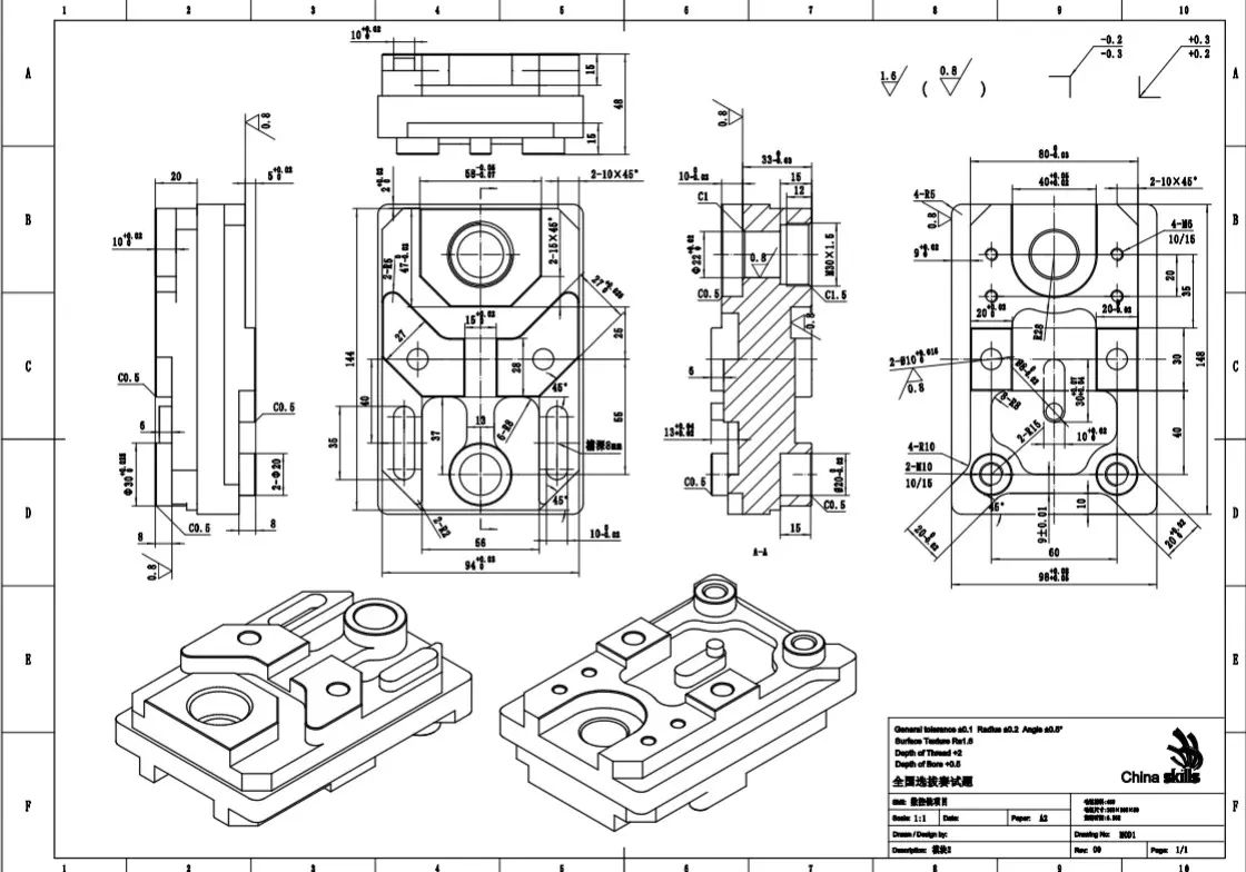
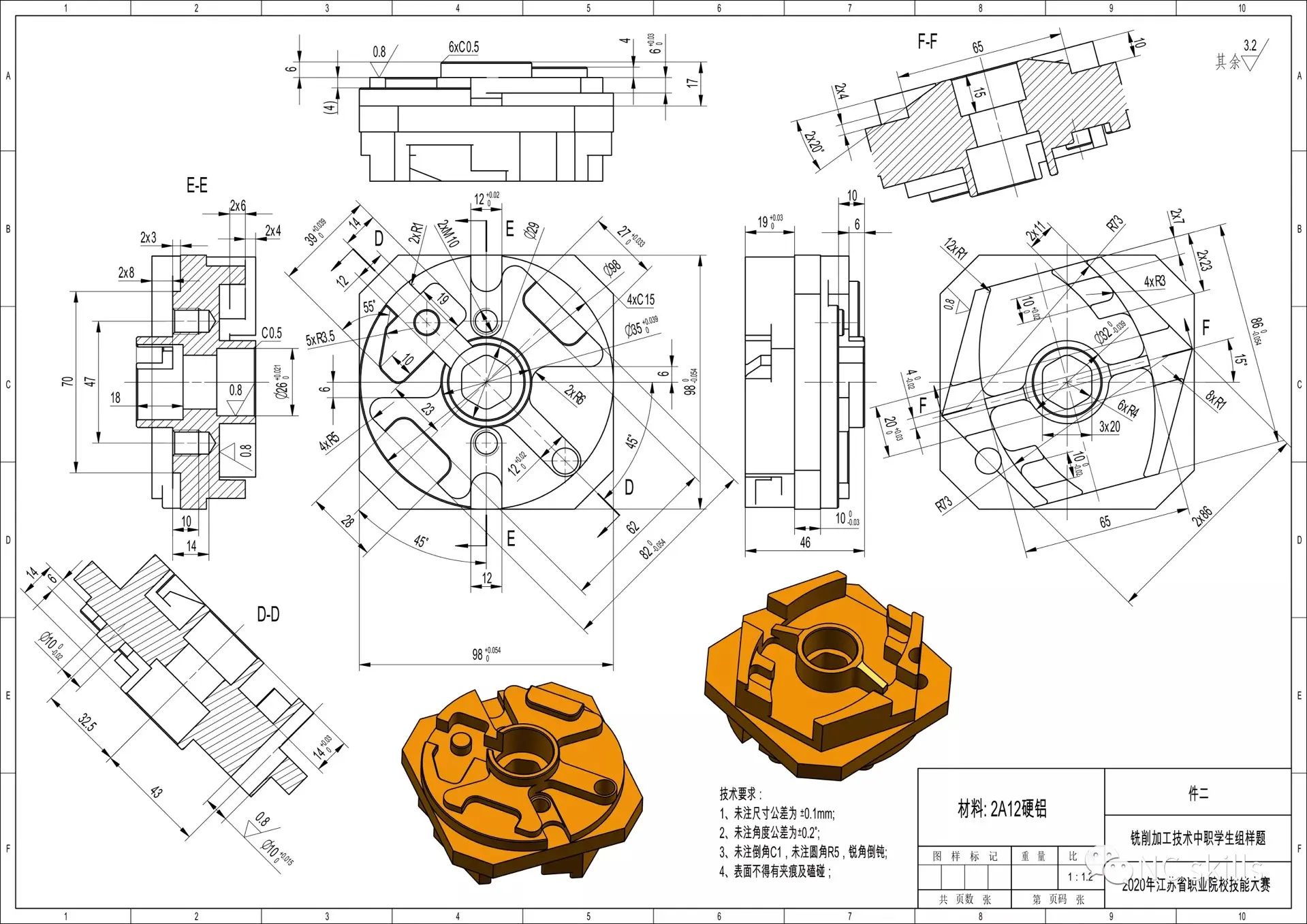
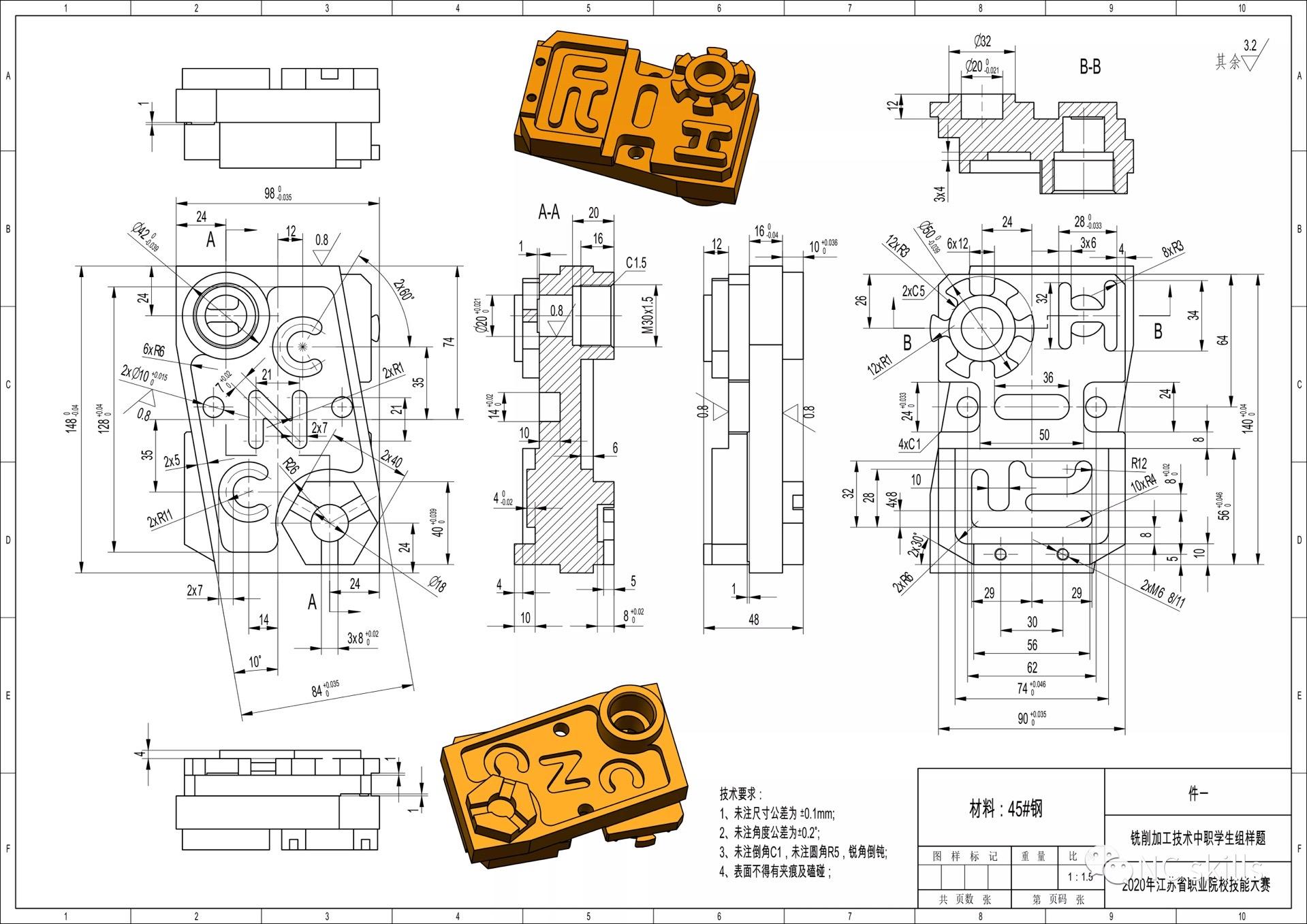
2D Drawing Example
The illustration below shows a sample part drawing with GD&T annotations, demonstrating how feature control frames and datum references are applied in a technical drawing.
Model-Based Annotation Example
In 3D CAD models, GD&T annotations can be embedded directly within the model, enabling Model-Based Definition (MBD). The example below illustrates GD&T implementation using SolidWorks.
9.0Frequently Asked Questions (FAQ)
Why use GD&T instead of traditional ± dimensioning?
GD&T offers a more precise and function-oriented approach to dimensional control. It better communicates design intent, reduces manufacturing errors, and improves assembly efficiency.
How do I choose the correct datum features?
Datum features should be selected based on the part’s function and assembly requirements. Typically, key functional surfaces, center axes, or primary mounting features are chosen as datums.
What’s the difference between ASME Y14.5 and ISO 1101?
ASME Y14.5 emphasizes functional relationships and assembly fit, and is commonly used in North America. ISO 1101 focuses more on general interoperability and international harmonization, and is widely used in Europe and Asia.
What are the key updates in the 2018 revision?
Major updates in ASME Y14.5-2018 include the removal of concentricity and symmetry symbols, revised profile tolerance expressions, enhanced support for Model-Based Definition (MBD), and clarified relationships between size and feature requirements.
10.0Recommended Resources
10.1Access to Standards:
10.2English Suggested Books:
《Geometric Dimensioning and Tolerancing Based on ASME Y14.5》
《GD&T for Designers and Engineers》
《Advanced Concepts of GD&T》
References
geotol.com/core-programs/2018-standards/
www.gdandtbasics.com/asme-y14-5-gdt-standard/
www.redriver.team/asme-vs-iso-understanding-the-differences/