
1.0What Is ISO 286?
1.1Introduction to ISO 286
ISO 286 is an international standard that defines tolerance grades, fundamental deviations, and fit types for holes and shafts. Widely used in mechanical engineering and manufacturing, it ensures proper assembly performance and interchangeability between mating parts.
1.2Core Functions of ISO 286
- Establishes a unified system for hole and shaft fits and tolerances
- Specifies standard tolerance grades (IT grades) for holes and shafts
- Provides calculation methods and tabulated data for limit and fundamental deviations
- Enables interchangeable and precise assembly between parts from different manufacturers
1.3Structure of the ISO 286 Standard
ISO 286-1:2010 – ISO system of limits and fits — Part 1: Bases of tolerances, deviations and fits
Applicable Size Range: Up to 3150 mm
🔗 Full text available: ISO 286-1:2010 PDF (EN)
Key Contents:
- Fundamentals of fits and tolerances: Definitions for dimensional tolerances, deviations, and fit types
- IT Grades: From IT01, IT0, IT1 to IT18 — the lower the grade number, the higher the precision
- Fundamental deviations: The limits above or below the nominal size for holes or shafts
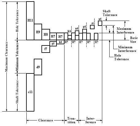
- Fit categories: Clearance fits, transition fits, and interference fits
ISO 286-2:2010 – ISO system of limits and fits — Part 2: Tables of standard tolerance grades and limit deviations for holes and shafts
🔗 Download the full reference tables: ISO 286-2:2010 PDF (EN)
Applicable Size Range: 0 to 4000 mm
Key Contents:
- Standard tolerance grade tables: Tolerance values by nominal size range
- Limit deviation tables: Upper and lower deviation values for hole/shaft combinations based on fit type
2.0Main Provisions of ISO 286
ISO 286 defines a systematic approach to tolerance grading for holes and shafts, providing tables for standard values. It is commonly applied in subtractive manufacturing (e.g., CNC machining) to control the precision of linear dimensions, especially for features not individually toleranced on engineering drawings.
2.1Typical Applications
- Cylindrical features: Such as shafts and holes requiring precise fits
- Parallel surfaces: To control critical spacing between components
IT Grades (International Tolerance Grades)
| Grade Range | IT01, IT0, IT1 to IT18 (extended to IT20+ in special cases) |
| Precision | Lower IT grade numbers correspond to tighter tolerances |
| Rule of Thumb | Every 5 IT grades increase the tolerance bandwidth by roughly 10x |
Tolerance and Fit Designation
ISO 286 uses a combination of letters and numbers to define fit specifications:
Letter: Indicates the position of the fundamental deviation (uppercase = hole, lowercase = shaft)
Number: Indicates the IT grade
Common fundamental deviation symbols:
- H, G, F, JSfor holes (uppercase)
- h, f, g, k, n, pfor shafts (lowercase)
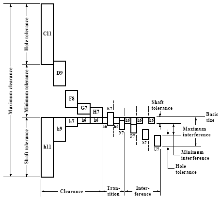
Types of Fits
| Fit Type | Description | Example |
| Clearance fit | Easy assembly with visible gap | H7/g6 |
| Transition fit | May result in clearance or slight interference | H7/k6 |
| Interference fit | Requires pressing or force for assembly | H7/p6 |
ISO 286 defines appropriate combinations of tolerance grades and fundamental deviations for each fit type.
Sample IT Grade Tolerances (in µm)
| Nominal Size Range (mm) | IT6 | IT7 | IT8 |
| 50 – 80 | 19 | 30 | 46 |
| 80 – 120 | 22 | 35 | 54 |
| 120 – 180 | 25 | 40 | 63 |
| 250 – 315 | 32 | 52 | 81 |
Example: IT6 = 19 µm means the total tolerance zone is 19 microns wide. The actual upper/lower limits depend on the deviation code used.
🔗 For a complete list of standard round bar tolerances by size and grade, download the full reference: ISO Round Bar Tolerances (PDF)
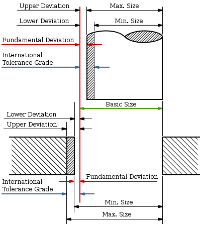
2.2Key Terminology in ISO 286
| Term | Definition |
| Nominal Size | The target size indicated on the drawing |
| Actual Size | The measured size after manufacturing |
| Upper Limit | The maximum permissible dimension |
| Lower Limit | The minimum permissible dimension |
| Tolerance | The difference between upper and lower limits |
| Limit Deviation | Maximum allowable deviation from the nominal size |
| Fundamental Deviation | Closest deviation from nominal; defines the fit type |
2.3ISO 286 Tolerances for Linear Dimensions
The table below provides the ISO 286 tolerance limits for linear dimensions based on different nominal dimension ranges, presented in micrometers (µm)
| Nominal Dimension Range (mm) |
ISO 286—International Tolerance Grade(IT Grades) Tolerance in micrometer(μm) |
|||
| over | up to | IT6 | IT7 | IT8 |
| 0 | 3 | 6 | 10 | 14 |
| 3 | 6 | 8 | 12 | 18 |
| 6 | 10 | 9 | 15 | 22 |
| 10 | 18 | 11 | 18 | 27 |
| 18 | 30 | 13 | 21 | 33 |
| 30 | 50 | 16 | 25 | 39 |
| 50 | 80 | 19 | 30 | 46 |
| 80 | 120 | 22 | 35 | 54 |
| 120 | 180 | 25 | 50 | 63 |
| 180 | 250 | 29 | 46 | 72 |
| 250 | 315 | 32 | 52 | 81 |
| 315 | 400 | 36 | 57 | 89 |
| 400 | 500 | 40 | 63 | 97 |
| 500 | 630 | 44 | 70 | 110 |
| 630 | 800 | 50 | 80 | 125 |
| 800 | 1,000 | 56 | 90 | 140 |
| 1,000 | 1,250 | 66 | 105 | 165 |
| 1,250 | 1,600 | 78 | 125 | 195 |
| 1,600 | 2,000 | 92 | 150 | 230 |
| 2,000 | 2,500 | 110 | 175 | 280 |
| 2,500 | 3,150 | 135 | 210 | 330 |
For a nominal dimension between 50 mm and 80 mm, using ISO 286 IT6 tolerance grade, the permissible deviation is ±19 µm.
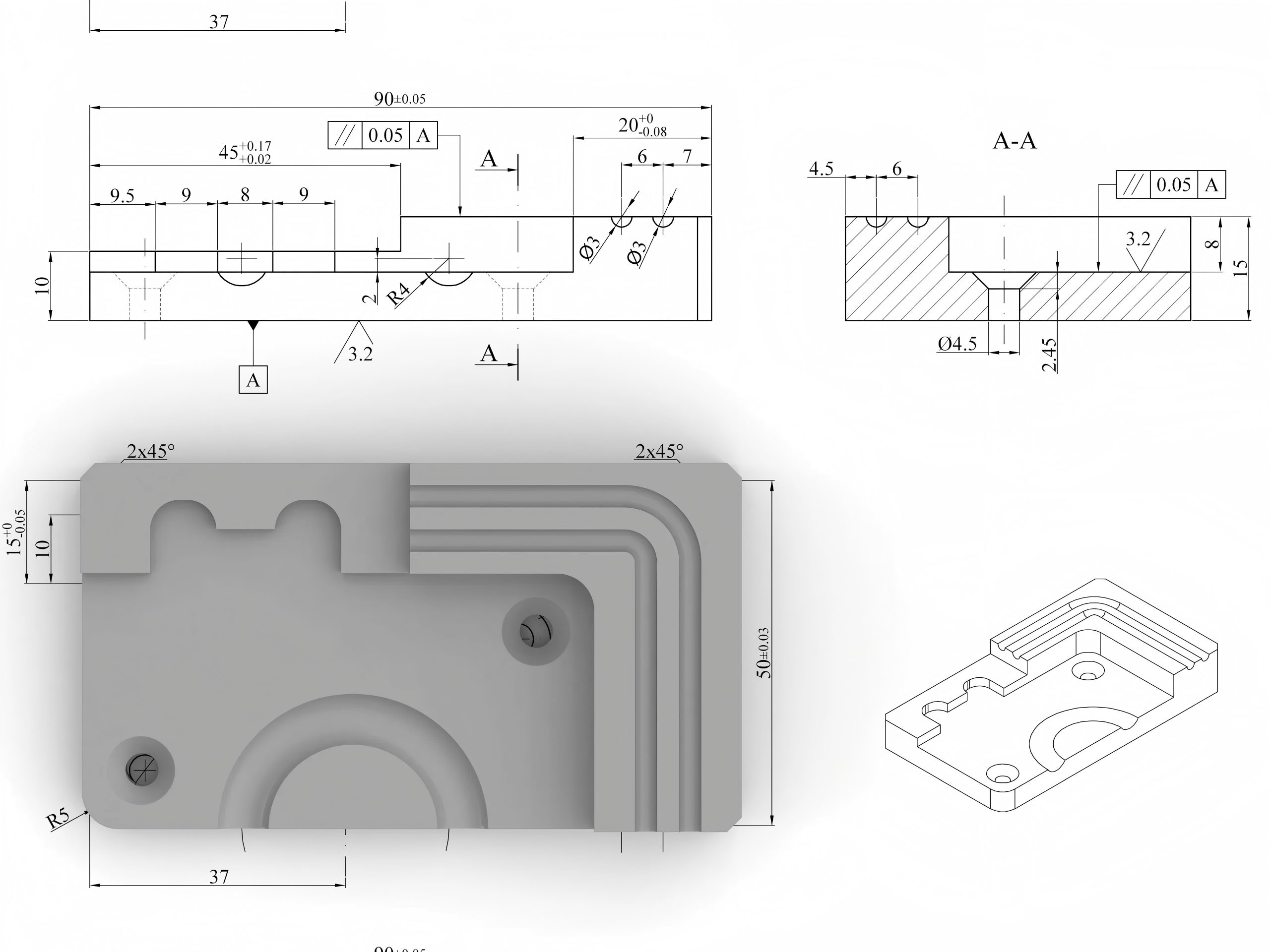
2.4ISO 286 and Geometric Dimensioning & Tolerancing (GD&T)
Geometric Dimensioning and Tolerancing (GD&T) is a symbolic language used to define the geometry and allowable variation in part features. Unlike linear tolerances that focus solely on size, GD&T governs the geometric relationships between features, ensuring proper function and assembly.
GD&T is governed by:
- ISO 1101– Geometrical Product Specifications (GPS)
- ASME Y14.5– North American GD&T standard
GD&T Tolerance Categories
| Category | Description |
| Form Tolerance | Controls geometric shape (e.g., flatness, roundness, straightness) |
| Orientation Tolerance | Controls angularity and alignment (e.g., parallelism, perpendicularity) |
| Position Tolerance | Controls the location of features (e.g., hole placement) |
| Runout Tolerance | Controls the rotational behavior of parts (e.g., wobble, concentricity) |
GD&T is ideal for function-critical features where precise assembly is required to ensure performance and reliability.
2.5ISO 286 in Practical Use
Applications include:
- Specifying tolerances: Designers define tolerance grades (e.g., H11, JS11, c11) for holes and shafts to control size deviation
- Selecting fits: Engineers reference ISO 286 tables to choose appropriate fits (clearance, transition, interference)
- Inspection and QA: Inspectors use ISO 286 criteria for go/no-go decisions and statistical process control
- Tooling and Gauging: Ensures compatibility with standardized cutting tools and gauges
- Interchangeability: Enables parts from different sources to fit and function properly
- Global Compatibility: Supports product consistency and compatibility across international supply chains
3.0Comparing GD&T and Traditional Tolerancing (ISO 286)
GD&T enhances and complements ISO 286 by introducing geometric controls. While ISO 286 focuses on size and fit, GD&T governs form, orientation, and positional accuracy.
3.1When to Choose GD&T or Traditional Linear Tolerancing?
| Aspect | Traditional Linear Tolerancing (ISO 286) | GD&T (ISO 1101) |
| Control Focus | Size and fits | Geometry: form, orientation, position |
| Complexity | Simple and easy to interpret | Complex; requires training |
| Inspection Method | Gauges, micrometers | CMMs, digital metrology |
| Cost Management | Good for rough machining cost control | Targets critical features for precision |
| Best Use Case | Non-critical structural parts | Functional, high-precision components |
3.2Advantages and Limitations of GD&T
Advantages:
- Precisely controls critical features to improve fit and reliability
- Minimizes interpretation ambiguity, clarifies design intent
- Looser tolerances can be applied to non-critical features, reducing cost
- Compatible with modern CMMs and automated inspection systems
Limitations:
- Requires specialized training and interpretation skills
- More complex inspection methods can increase quality control costs
- Overuse or misuse can complicate manufacturing and delay production
4.0ISO 286 vs GD&T
| Feature | ISO 286 | GD&T |
| Control Focus | Hole/shaft fits, dimensional tolerances | Form, orientation, position, runout |
| Notation Style | Letter + IT grade (e.g., H7/h6) | Feature control frame + symbols (e.g., ⊥, ⌀) |
| Application Scope | Linear dimensions, sliding/press fits | Critical functions, complex geometry |
| Design Intent | Interchangeability and fit | Functionality and performance |
In practice, ISO 286 and GD&T are often combined to provide a comprehensive control system for both size and geometry.
4.1Tolerance Stack-Up and Accumulated Error
In assemblies, multiple tolerances may combine and lead to cumulative error, known as a tolerance stack-up.
Engineers perform tolerance analysis (e.g., worst-case, statistical methods) to predict total deviation and ensure final assembly functionality.
🔗 For detailed shaft/hole deviation combinations used in clearance, transition, and interference fits, refer to the full chart: ISO Tolerances for Holes and Shafts (PDF)
ISO 286 provides a reliable framework for early-stage design optimization and tolerance planning.
4.2ISO 2768 vs ISO 286: Key Differences
| Category | ISO 2768 (General Tolerances) | ISO 286 (Limits and Fits) |
| Application Scope | General linear/angular dimensions | Hole and shaft fits with defined deviation |
| Tolerance Type | General size, angle, form tolerances | Fit-specific tolerances (clearance, etc.) |
| Grade Levels | Fine, medium, coarse, very coarse | H7/h6, H11/c11, etc. |
| Use Case | Non-critical dimensions, simplified drawings | Precise fits, force transmission, critical assembly |
| Notation Method | Applies default tolerances globally | Requires explicit fit designation per feature |
5.0Conclusion
- ISO 286 provides a globally recognized framework for limits and fits in mechanical assemblies.
- GD&Textends control to geometric relationships, enabling precision and functional performance.
- ISO 2768 offers a simplified approach to tolerancing for non-critical parts.
- Engineers should apply these standards judiciously based on functionality, assembly requirements, cost, and design complexityto achieve optimal manufacturing results.
6.0Downloadable Resources
- ISO 286-1:2010 PDF (EN) – Basis of tolerances, deviations, and fits under the ISO code system for linear sizes.
- ISO 286-2:2010 PDF (EN) – Standard tables of tolerance grades and limit deviations for holes and shafts.
- ISO Tolerances for Holes and Shafts (PDF) – Practical deviation chart for common fits.
- ISO Round Bar Tolerances (PDF) – Tolerance values by nominal diameter and grade for shafts.