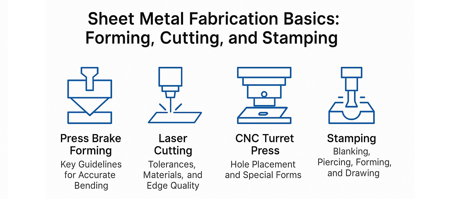
钣金制造涉及一系列成型和切割工艺,每种工艺都有特定的设计考量,以确保质量、效率和成本效益。本指南重点介绍以下领域的基本成型指南: 折弯成型以及切割原则 激光切割机 和 数控转塔压力机.
1.0成型基础:折弯机成型指南
1.1折弯机成型的关键设计指南
- 尺寸标注策略:尽可能在单一方向上标注零件尺寸。由于折弯成型是一个连续的折弯过程,每次折弯都会带来轻微的尺寸变化。单向标注尺寸符合工艺流程,有助于控制公差累积。
- 弯曲公差:弯曲公差 +/-0.007 英寸建议。虽然可以实现更严格的公差,但这会显著增加生产成本。
- 一致的弯曲半径:尽可能对零件的所有折弯使用相同的折弯半径。这可以减少设置更改。最好使用分数英寸为单位的半径,因为折弯机模具的尺寸是相应的。
- 特征到边缘尺寸标注:尺寸标注应从特征到边缘,而不是跨多个平面的特征到特征。特征到折弯处的尺寸可能需要特殊的测量或夹具,从而增加成本。
- 关键尺寸:只有真正关键的尺寸才应如此指定。不必要的严格公差会导致制造成本过高。
- 外部尺寸与内部尺寸:除非内部尺寸至关重要,否则始终使用外部尺寸来确保成型精度。
1.2钣金设计中的关键成形考虑因素
金属板材成形的关键尺寸: 使用 外部尺寸 作为测量的主要参考,除非 内部尺寸 功能至关重要。这种方法简化了检查,减少了公差累积,并最大限度地降低了不必要的制造成本。
1.3浮雕和偏移
除非整体高度至关重要,否则压花和偏移尺寸应参考材料的同一侧。过度指定可能会不必要地增加零件成本。
1.4弯曲半径建议
通常来说, 内弯半径 半径应等于材料厚度。较小的半径可能会导致较软金属出现材料流动问题,并可能导致较硬材料开裂。
1.5折弯止裂
当在边缘附近成型时,弯曲释放可防止撕裂。
- 从边缘到弯曲处的距离至少应等于弯曲半径。
- 释放深度应超过弯曲半径,释放宽度应至少等于材料厚度,最好为厚度 + 1/64 英寸。
1.6近孔成型
为避免弯曲过程中孔变形,请遵循以下准则:
- 孔径小于1:最小距离D=2T+R
- 直径大于1英寸的孔或槽:最小距离D=2.5T+R
(T = 材料厚度,R = 弯曲半径)
1.7形状高度与厚度的比率
钣金的最小形状高度(D): D = 2.5T + R。较低的高度也是可以的,但通常需要昂贵的二次操作。
1.8边缘失真
变形造成的边缘突出量可能高达材料厚度的一半。对于较厚的金属或较小的半径,边缘修整可以防止出现不可接受的突出量。
2.0激光切割基础知识
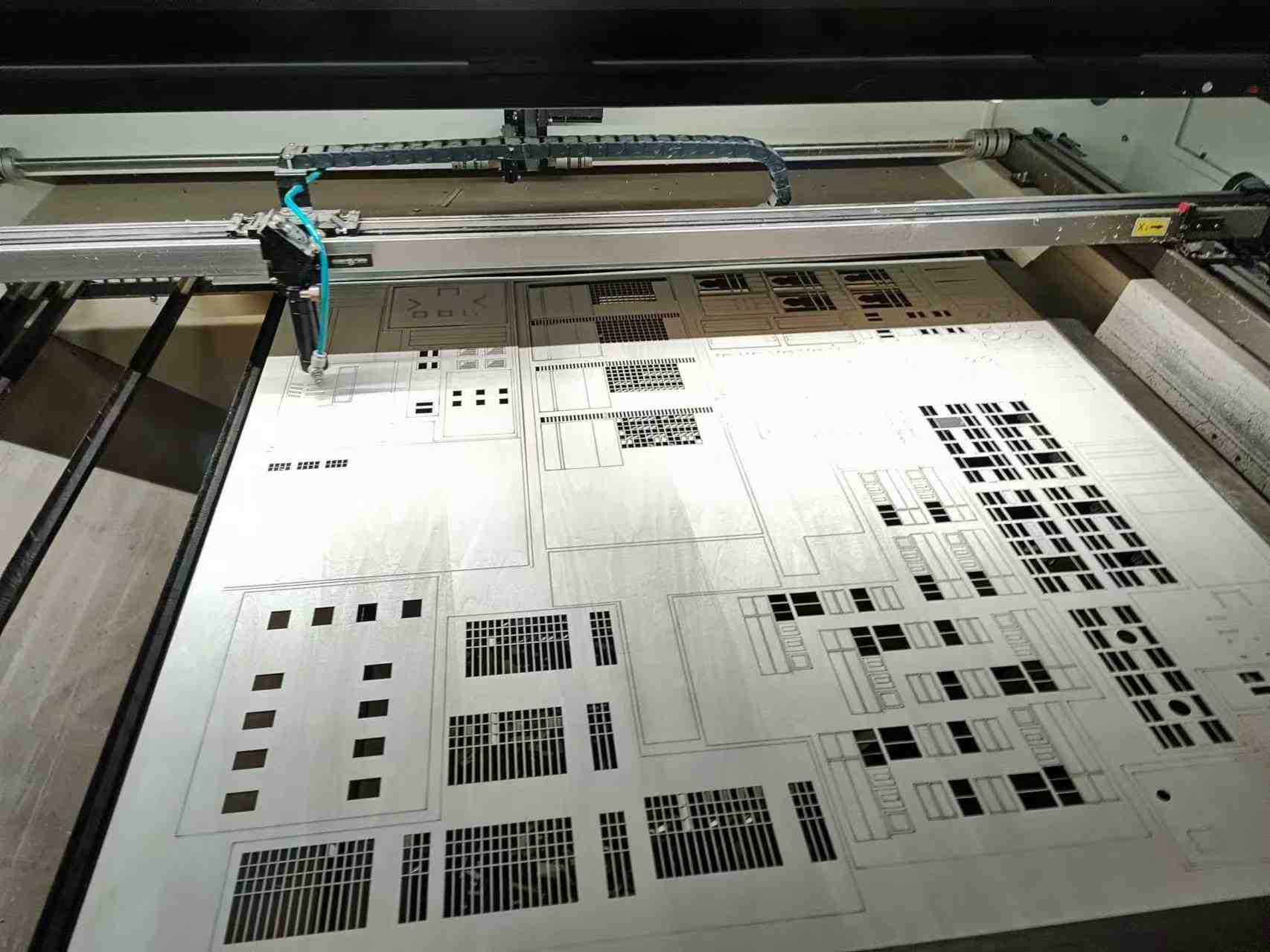
2.1公差和切割极限
- 标准特征间公差: +/-0.004 英寸
- 最小切割宽度: 008英寸,由光束宽度决定。
2.2材料限制
反射率、厚度和可燃性这三个主要因素限制了激光切割:
- 最大厚度: 金属高达 3/8英寸可以切割,但边缘质量会随着厚度的增加而下降。
- 反射率:铜或银等高反射性金属会散射光束,因此不适合。
- 易燃:切割前应进行热敏感或易燃材料测试。
2.3可接受的材料
- 钢材(不锈钢、CRS、HRS)
- 铝(可能需要去毛刺)
- 镀锌钢和镀锌钢
- 塑料和卡片纸(需经过耐热和易燃性测试)
2.4不可接受的材料
- 铜和贵金属(高反射率)
- 纸料(除非经过阻燃处理)
2.5热影响区(HAZ)
激光切割会在边缘处引入局部硬化,这可能会影响攻丝或铰孔等二次操作,尤其是在较厚的金属上。
2.6孔径考虑因素
激光切割孔呈略锥形(入口直径>出口直径)。最小孔径可小至20%的坯料厚度。
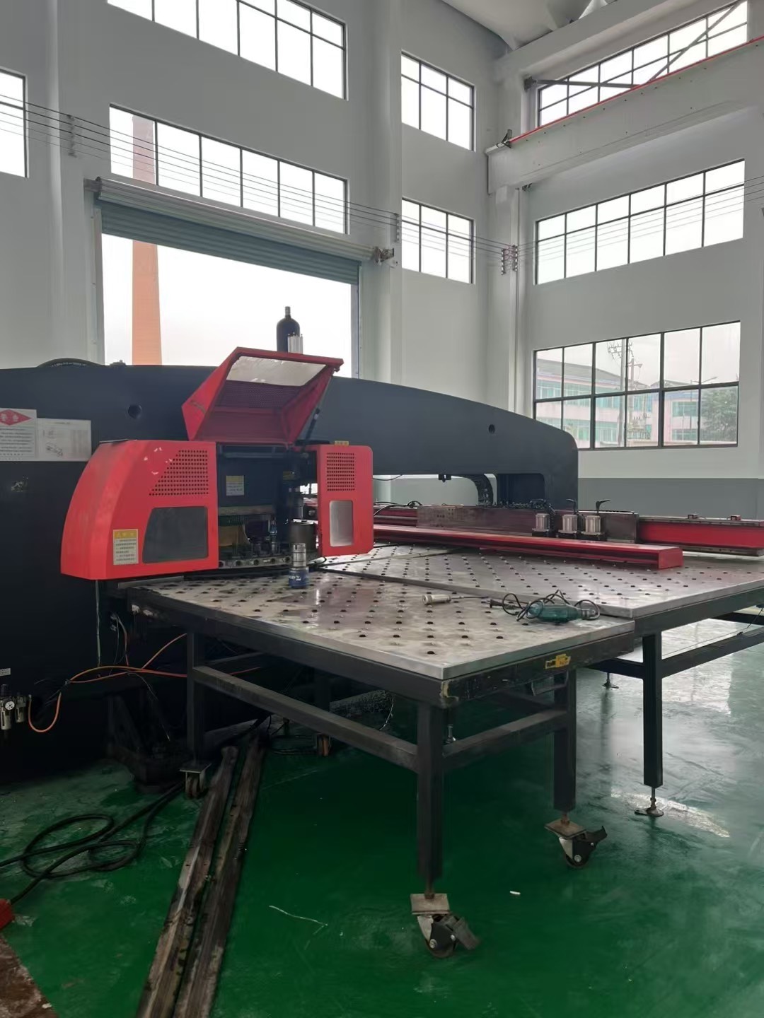
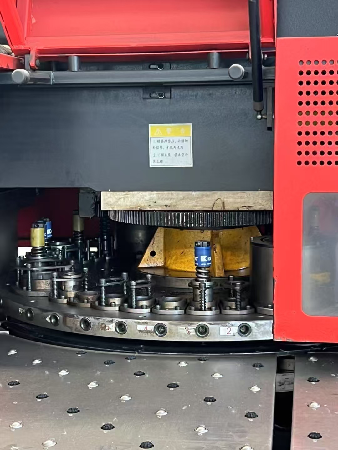
3.0数控转塔压力机基础知识
这 数控转塔压力机 对于使用标准“软工具”进行小批量到中批量生产、原型制作和经济高效的生产来说非常高效。
3.1公差和尺寸
- 特征间公差: +/-0.004 英寸
- 冲孔公差: +/-0.002 英寸
- 使用有意义的基准点(例如孔中心)而不是边缘,因为边缘可能会变细或错位。
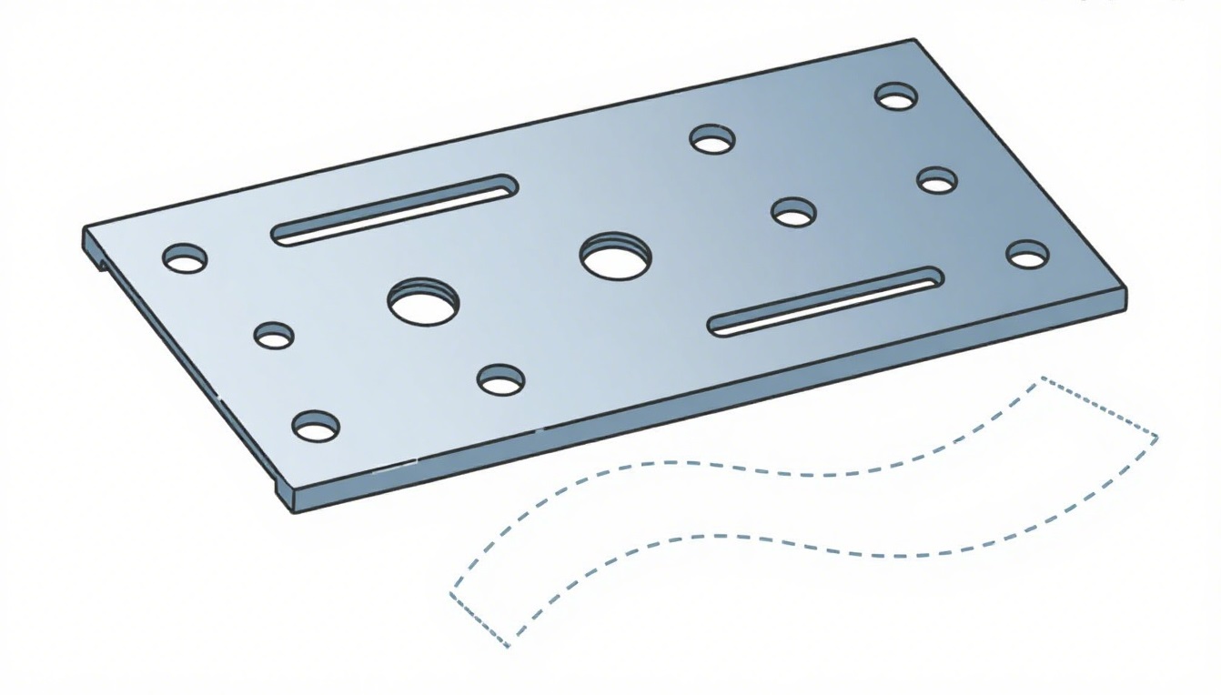
3.2特殊表格
转塔压力机可加工各种形状,包括沉头孔、压花、偏置、卡轨、半剪切和焊接凸起。成形深度必须小于 5/16 英寸,并适合直径为 3.5 英寸的圆。
3.3孔到边缘的间隙
至少保留孔 一种材料厚度 远离边缘,避免鼓胀。对于紧固孔,应留出额外的腹板厚度,以承受额外的应力。
3.4孔径与厚度的比率
孔径不应小于材料厚度。材料抗拉强度越高,冲头直径就越大。
3.5功能布局
保持相邻成形特征之间的间隙,以避免冲压过程中发生压扁。渐进式模具可以高效处理小型零件,并降低初始模具成本。
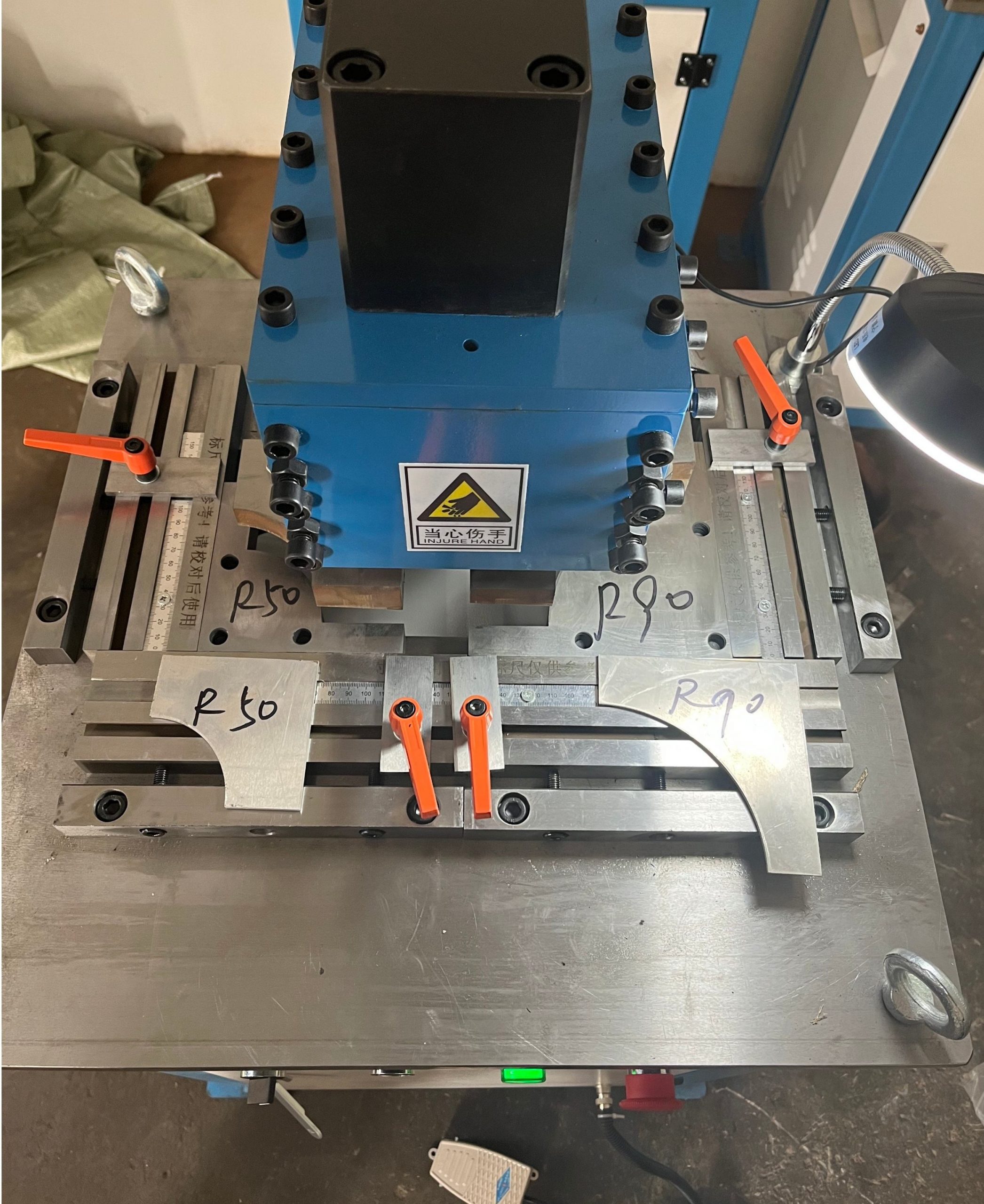
3.6步冲大半径
通过使用扁平工具多次敲击来形成大半径,从而产生扇贝形边缘,可以通过去毛刺来使其变得光滑。
3.7埋头孔
根据材料厚度和公差要求,可以成型、冲压或加工埋头孔:
- 形成:成本低,适用于薄规格(≤18 规格)。
- 已打孔:常见于厚度大于 18 的规格。
- 冲孔+机加工:适用于坚硬或厚重的金属。
- 机加工完成:成本较高,仅用于高精度或较厚的材料。
4.0冲压基础:精密钣金冲压基本指南
4.1冲裁:尺寸精度和边缘质量
落料是使用冲头和模具从金属板材上切割出扁平形状的工艺过程。尺寸精度通常在 剪切面积 或者在冲头侧“切割带”,因为模具侧的突破会降低精度。
对于一般的冲裁和剪切操作, 液压联合冲剪机 和 多功能联合冲剪 ... 广泛应用于中小批量生产,因为它们将冲孔、剪切和切口功能结合在一个装置中。
4.2角落
可以使用尖角,但会增加刀具磨损和成本。为了延长刀具寿命,应指定等于 ½ 材料厚度 或者至少 0.015英寸. 对于精确的角部修整,特别是厚规格金属板, 金属板角切口机 通常用于实现干净、无毛刺的角落。
4.3凹口和突出部分
- 最小凹口或突出部分宽度: 5×材料厚度
- 最大缺口长度: 5×材料厚度
4.4截止值
冲裁时使用三种常见的截止类型:
- 直/方截止:最经济
- 半圆或部分半径截止:价格适中
- 全半径截止:不推荐,因为它会留下不可避免的“羽毛边缘”毛刺
4.5穿孔:孔和边缘设计
穿孔是使用冲头和模具在金属板上打孔。
- 孔径:最小尺寸应为 ≥1.2×材料厚度适用于低碳钢和 ≥2×厚度 适用于不锈钢或高强度合金。
- 边缘到孔的距离:至少维持 2×材料厚度(腹板宽度)以防止鼓胀。
为了在较厚的材料上进行精确冲孔, 液压联合冲剪机 由于其稳定的冲压力和一次冲程可处理多个操作的能力,因此通常受到人们的青睐。
4.6成型:折弯释放和孔位定位
冲压成型遵循类似的原则 数控折弯成型.
- 折弯止裂:沿 L 形特征提供缓解,以防止撕裂。建议: 宽度 = 2T,深度 = T + R(T = 厚度,R = 弯曲半径)。
- 边缘凸起:V 形弯曲公差过小可能会导致凸起;弯曲释放可最大限度地减少此问题。
- 孔与型材之间的距离:至少放置孔 5T+R远离弯曲处以避免变形。
- 槽至模板距离:长槽至少应 4T+R从弯道。
对于形状复杂的边缘, 金属板角切口机 通常用于在弯曲之前去除多余的材料,减少角落处的应力并提高成型精度。
4.7绘图:形状和半径
拉伸用于形成深度或复杂的 3D 形状,例如外壳、外壳和结构部件。
- 首选形状:圆形最容易绘制,也最经济。正方形只要角半径够大即可,而不规则或混合形状会增加模具成本。
- 半径建议:
- 冲头和凹模半径: ≥4×材料厚度
- 零件半径: ≥6×材料厚度(采用绘画品质的材料)
深拉伸通常在 机械冲压机 或者 液压深拉压力机 以便更好地控制成型力。
5.0结论
优化金属冲压设计需要在精度、成本和可制造性之间取得平衡。遵循这些指导原则并选择合适的设备——例如 液压联合冲剪机 用于多功能冲孔和剪切, 多功能联合冲剪 ... 适用于多种冲裁操作,以及 金属板角切口机 实现准确、干净的转角精加工——制造商可以以较低的生产成本获得高质量的冲压件。
6.0常见问题解答:钣金成型、切割和冲压
问题1:钣金成型的最佳弯曲半径是多少?
答:建议的内弯半径应等于材料厚度。较小的半径可能会导致硬金属开裂或软金属过度拉伸。
问题2:激光切割可以用于所有类型的金属吗?
答:不可以。高反射性金属(例如铜、银和一些贵金属)不适合激光切割,因为它们会散射光束。厚度超过 3/8 英寸的厚金属可以切割,但边缘质量会下降。
问题 3:金属板上的孔和折弯之间的最小距离是多少?
答:对于直径小于 1 英寸的孔,最小距离 (D) 应为 2T + R。对于较大的孔或槽,D 应为 2.5T + R,其中 T = 材料厚度,R = 弯曲半径。
问题4:为什么在冲压过程中要使用钣金角切口机?
一个: 金属板角切口机 用于实现干净、无毛刺的折弯角,并在成型前去除多余的材料。这可以减少折弯角处的应力集中,并提高折弯精度。
问题5:哪些机器最适合小批量钣金制造?
答:对于小到中型生产批次, 液压联合冲剪机 和 多功能联合冲剪 ... 非常理想,因为它们将冲孔、剪切和切口功能结合在一个装置中。
Q6:数控转塔压力机冲孔和激光切割有什么区别?
答:数控转塔冲压机冲孔速度更快,适合加工重复形状,并且可以制作浮雕或倒棱等特殊形状,但孔边缘会略微变细。激光切割边缘更光滑,更适合加工复杂轮廓,但对反光材料有限制。