
- 1.0What Is a Worm Gear Drive? Definition and Core Components
- 2.0Principle of Worm Gear Drives: Speed Reduction, Torque Multiplication, and Self-Locking
- 3.0Core Types of Worm Gear Drives: Structural Classifications
- 4.0Manufacturing Processes of Worm Gear Drives: Precision Defines Performance
- 5.0Material Selection: Balancing Wear Resistance and Anti-Seizure Performance
- 6.0Typical Applications of Worm Gear Drives: Value Defined by Use Case
- 7.0Conclusion: Advantages and Limitations of Worm Gear Drives
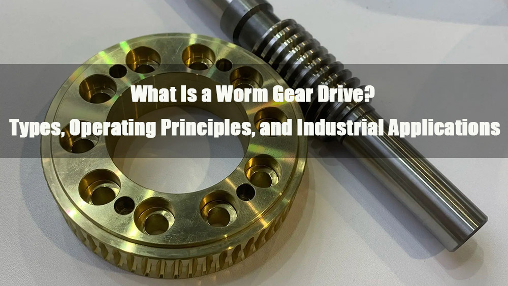
In the field of mechanical power transmission, worm gear drives stand out for their unique combination of non-parallel shaft orientation and high reduction ratios. They provide an essential solution for applications that demand low speed, high torque, and compact design. From the smooth lifting of elevators to the precise tuning of musical instruments, worm drives play a critical role in enabling reliable and efficient motion control.
1.0What Is a Worm Gear Drive? Definition and Core Components
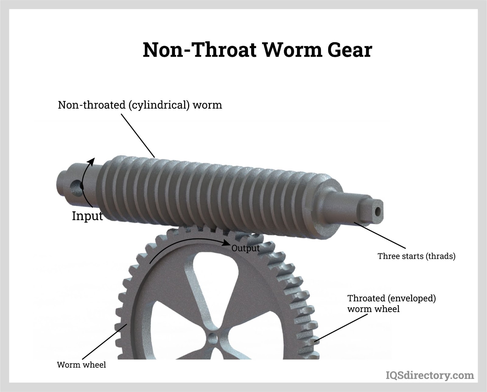
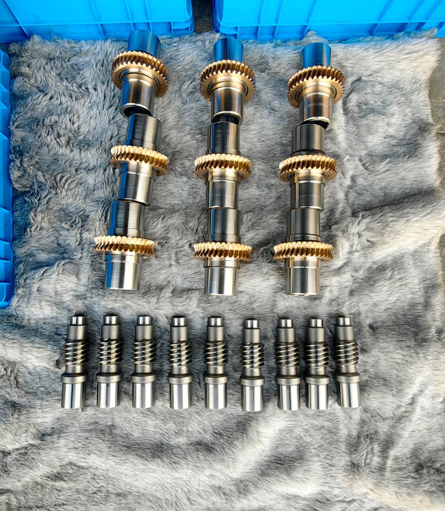
A worm gear drive is a type of gear system used to transmit motion and power between two non-parallel, non-intersecting shafts (typically at a 90° angle). It consists of two main elements: the driving part, the worm, and the driven part, the worm wheel. Motion transfer occurs through conjugate tooth surfaces in contact, essentially forming a mechanical amplification system based on “helical engagement.”
Key Component Characteristics
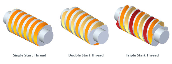
- Worm: Shaped like a threaded cylinder, its teeth form a continuous helical line (similar to a threaded bolt). Based on the number of threads, worms are classified into single-start(one thread, higher reduction ratio, strong self-locking capability) and multi-start (2–4 threads, higher efficiency, lower reduction ratio). The worm functions as the input element of the drive.
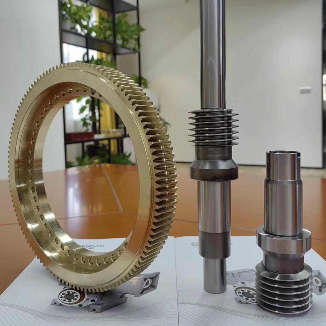
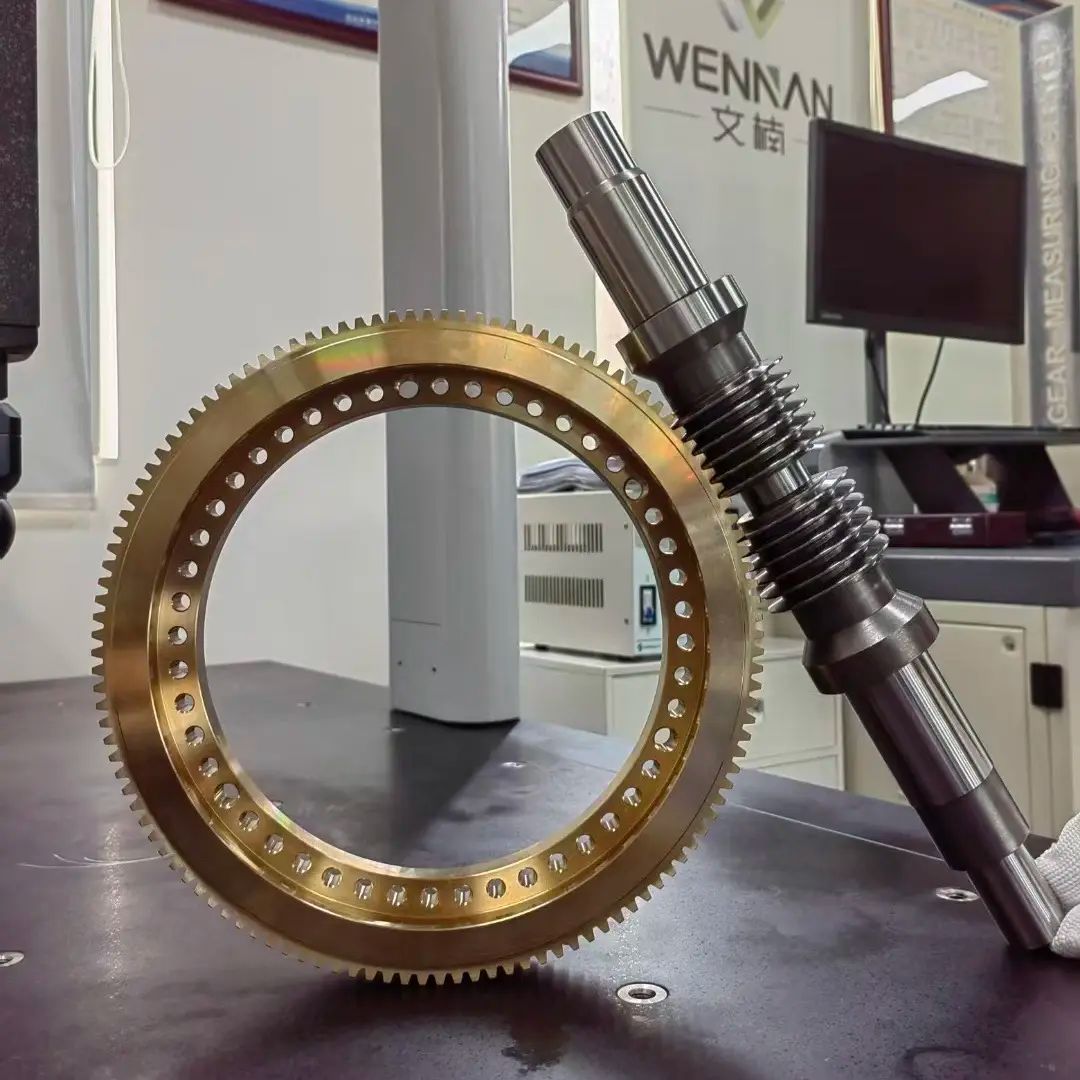
- Worm Wheel: Resembles a gear disk but with tooth grooves shaped to perfectly match the worm’s helical profile (conjugate tooth surface) for precise, backlash-free engagement. Large worm wheels are often manufactured with a bronze gear rim and a cast iron or steel hub, balancing wear resistance with cost efficiency. The worm wheel serves as the output element.
2.0Principle of Worm Gear Drives: Speed Reduction, Torque Multiplication, and Self-Locking
The key advantage of worm gear drives lies in their ability to deliver large speed reduction and torque amplification within a compact system. The operation can be explained in three stages:
- Power Transmission: Helical Engagement
The worm, driven by a motor or power source, rotates and its helical thread pushes against the worm wheel’s grooves, causing the wheel to rotate about its axis. The direction of rotation depends on both the worm’s lead direction (left-hand or right-hand thread) and its rotational input. This can be determined using the “right-hand/left-hand rule.” - Reduction Ratio and Torque Multiplication: Defined by Geometry
The transmission ratio is determined solely by the worm’s number of starts (z₁) and the worm wheel’s number of teeth (z₂), independent of module or diameter. The formula is:
$$i = \frac{n_1}{n_2} = \frac{z_2}{z_1}$$
For example, a single-start worm (z₁ = 1) driving a 40-tooth wheel (z₂ = 40) results in a 40:1 ratio—meaning the worm must rotate 40 turns for the wheel to complete one turn. By the principle of power conservation (neglecting losses), reduced speed translates into proportional torque multiplication, enabling worm drives to power heavy-duty machinery such as elevators and presses.
- Self-Locking: Preventing Back-Driving
When the worm’s lead angle is smaller than the friction angle of the gear mesh, the worm wheel cannot drive the worm in reverse. This is known as the self-locking effect. Single-start worms, with smaller lead angles, are more likely to provide self-locking, making them suitable for applications requiring reverse motion prevention (e.g., manual hoists, tuning mechanisms). Multi-start worms, with larger lead angles, generally do not offer self-locking.
3.0Core Types of Worm Gear Drives: Structural Classifications
Worm gear drives can be categorized based on the structural design of the worm and worm wheel. Each type offers distinct advantages depending on load capacity, efficiency, and precision requirements.
By Overall Drive Structure
- Non-Throated Worm Gear Drive: Both the worm and worm wheel have no throats (grooves). The simplest design with minimal contact area, suitable for light-duty and low-precision applications such as basic conveyors.
- Single-Throated Worm Gear Drive: The worm wheel features a concave throat profile that partially wraps around the worm, increasing contact area compared to the non-throated type. Provides improved efficiency and load capacity, commonly used in industrial systems requiring higher accuracy, such as actuators and lifting mechanisms.
- Double-Throated Worm Gear Drive: Both worm and worm wheel incorporate throated designs (concave worm and convex wheel). This configuration delivers maximum contact area, highest load capacity, and requires precision manufacturing. It is suited for heavy-duty equipment such as industrial presses and precision machine tools.
By Worm Design
- Enveloping Worm (Hourglass Worm): The worm’s diameter increases from the center toward the ends, forming an “hourglass” profile. This creates larger contact areas with the worm wheel, resulting in higher transmission efficiency. Typically applied in medium-to-heavy load scenarios.
- Double-Enveloping Worm (Conjugate Surface Worm): Combines an enveloping worm with a fully enveloping worm wheel. The tooth surfaces maintain uniform contact during engagement, offering superior load capacity and precision compared to standard enveloping worms. Commonly used in high-precision, heavy-load applications such as robotic joints and heavy-duty reducers.
By Worm Wheel Design
- Milled Flat-Face Worm Wheel: Manufactured by milling, with a 0° helix angle and flat tooth surface. Engagement occurs at limited points, resulting in low accuracy and low cost. Suitable only for light-duty uses such as toy drives.
- Hobbed Flat-Face Worm Wheel: Produced by hobbing, offering higher pitch accuracy, smoother surfaces, and better wear resistance than milled wheels. Suitable for medium-load, general-precision applications such as standard gear reducers.
- Convex Worm Wheel: Features a curved profile, which when paired with a concave worm (such as in a double-throated design), creates “dual-groove engagement.” This provides the highest contact ratio, best efficiency, and maximum load capacity, making it ideal for high-precision, heavy-duty systems such as machine tool feed mechanisms.
4.0Manufacturing Processes of Worm Gear Drives: Precision Defines Performance
The tooth surfaces of the worm and worm wheel are conjugate curved surfaces, requiring specialized processes and equipment to ensure proper meshing accuracy. The manufacturing routes for worms and worm wheels differ significantly.
Worm Manufacturing Processes
The key is maintaining accuracy and consistency of the helical teeth, classified into three levels by precision:
- Low Precision (Grades 9–12): Produced by milling, using disk-type cutters (for small modules) or finger cutters (for larger modules) directly on a milling machine. No special equipment required, suitable for light-duty applications such as manual winches.
- Medium Precision (Grades 7–8): Produced by hobbing with a worm hob (a tool conjugate to the worm wheel). The process involves generating motion (hob rotation plus workpiece feed) on a gear hobbing machine. High efficiency and reliable accuracy make this the mainstream method for mass production, e.g., automotive steering worms.
- High Precision (Grades 4–6): Produced by hobbing + grinding. After hobbing, finishing is performed with a worm grinding wheel on a specialized grinder to correct errors and reduce surface roughness (Ra ≤ 0.8 μm). Suitable for precision machine tools and robotics.
Worm Wheel Manufacturing Processes
The worm wheel must ensure accurate conjugation with the worm. Two main approaches are used:
- Integral Worm Wheel: For small-size, light-duty applications (e.g., miniature gearboxes), a single blank is hobbed directly into its final form. No assembly required.
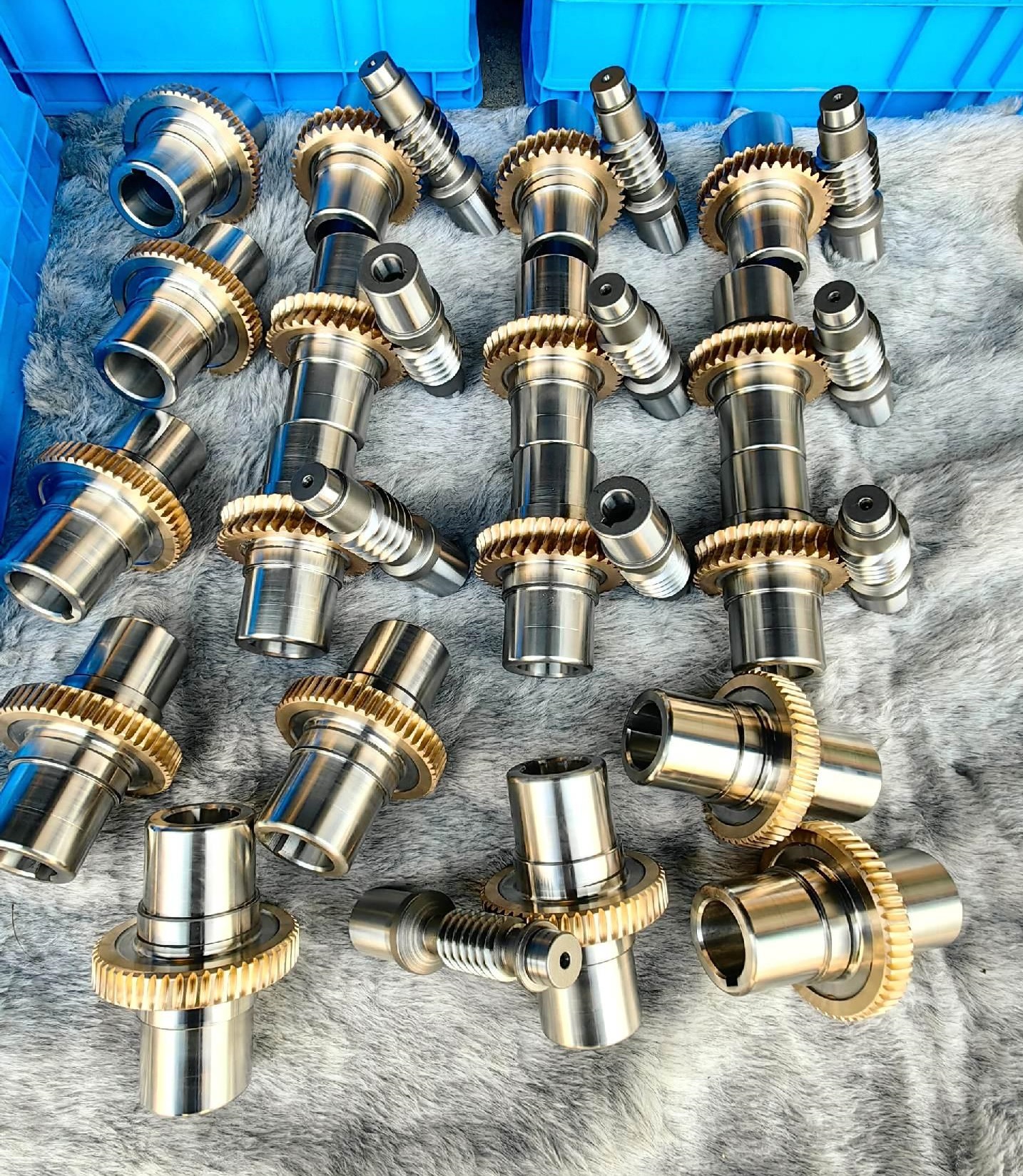
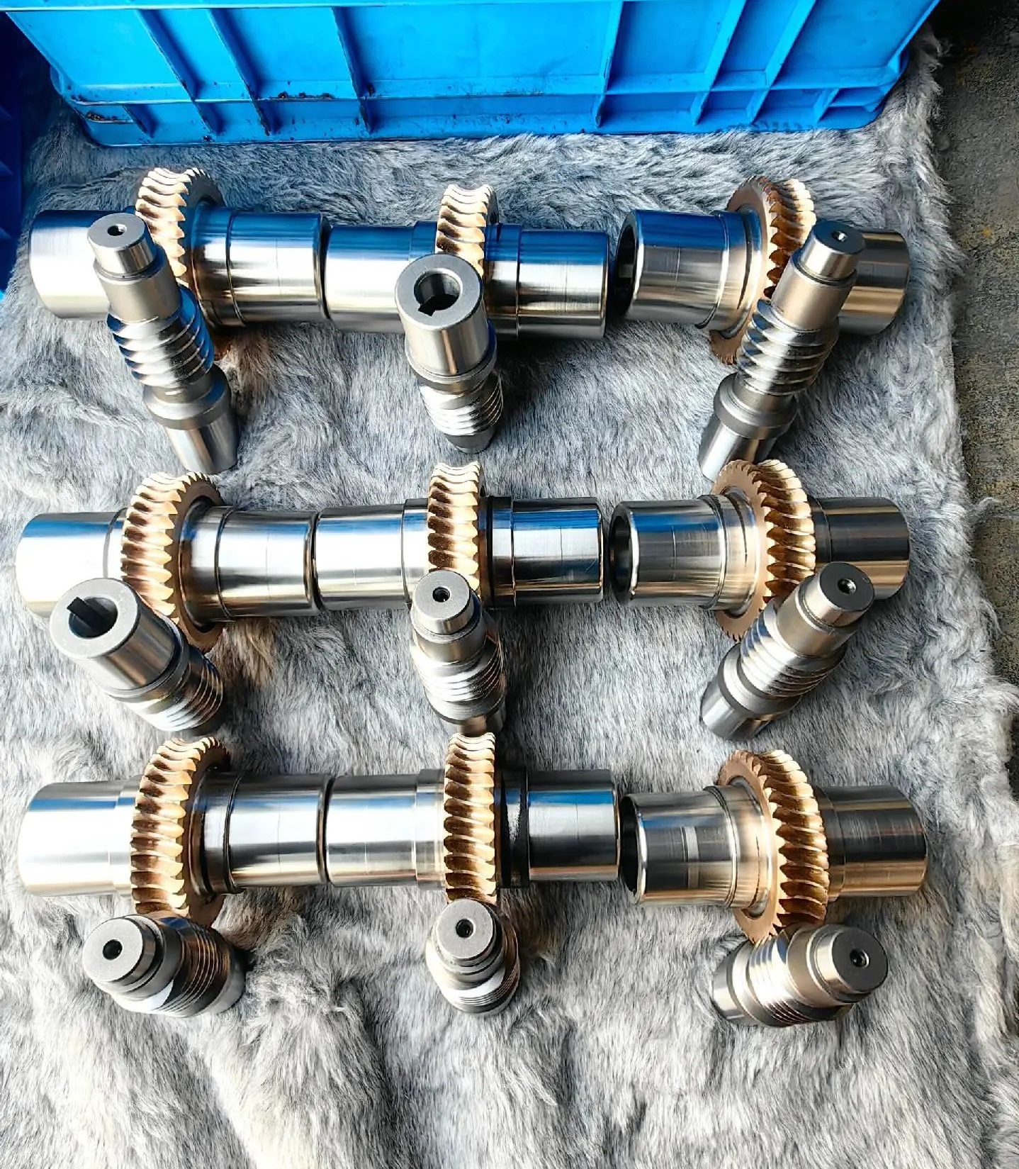
- Composite Worm Wheel: For large-size, heavy-duty applications (e.g., lifting equipment). Made from two parts:
- (1) a bronze gear rim, hobbed (and sometimes shaved) for accuracy;
- (2) a cast iron or steel hub, turned on a lathe for the outer diameter and bolt holes;
- (3) assembled via interference fit or bolts, balancing wear resistance with cost.
Key Manufacturing Equipment
- Basic Processing: Gear milling machines (low-precision worms), lathes (hubs).
- Core Processing: Gear hobbing machines (medium/high-precision worms and wheels), worm wheel shaving machines (wheel finishing).
- High-Precision Processing: Worm grinders (precision worms), hydraulic presses (assembly of composite wheels).
5.0Material Selection: Balancing Wear Resistance and Anti-Seizure Performance
Worm gear sets rely on a “hard-soft pairing” to balance durability and anti-galling properties.
- Worm Materials: Require high hardness and wear resistance. Common choices include 45 steel (induction hardened, HRC 55–60) and 20CrMnTi (carburized and quenched, HRC 58–62) for long-lasting tooth surfaces.
- Worm Wheel Materials: Require high anti-friction and anti-galling performance. Common options include tin bronze (ZCuSn10Pb1, for high-speed, heavy-duty), aluminum bronze (for medium-speed, medium-load), and cast iron (for low-speed, light-duty). In light applications, nylon may be used to prevent scuffing failures.
6.0Typical Applications of Worm Gear Drives: Value Defined by Use Case
Thanks to their compact structure, high reduction ratio, smooth operation, and self-locking ability, worm gear drives are widely applied across multiple sectors:
Industrial Applications
- Conveying and Lifting: Conveyors (speed reduction with torque increase), elevators and hoists (self-locking for safety, smooth speed control).
- Heavy Machinery: Industrial presses (high torque output), machine tool feed systems (high-precision motion for machining accuracy).
- Special Equipment: Transfer cases in four-wheel-drive vehicles (crossed-axis transmission), braking systems (self-locking to prevent reverse motion).
Consumer and Precision Applications
- Musical Instrument Tuning: Guitar and violin tuning pegs (self-locking to hold string tension, precise adjustment).
- Safety Devices: Automatic security doors (self-locking to prevent forced opening).
- Everyday Machinery: Boat trailer winches (lifting heavy loads with torque multiplication), fishing reels (smooth winding with anti-reverse).
7.0Conclusion: Advantages and Limitations of Worm Gear Drives
Key Advantages:
- Large single-stage reduction ratios (10–100) in a compact form
- Smooth and quiet operation
- Inherent self-locking capability
- Right-angle shaft arrangement without complex reversing mechanisms
Main Limitations:
- High sliding friction between tooth surfaces, resulting in lower efficiency (typically 60–70% for single-start worms)
- Relatively fast wear, requiring regular lubrication
- Not suitable for high-speed or high-power applications due to heat generation and risk of galling
Overall, worm gear drives represent a classic “efficiency-for-performance” trade-off, remaining an indispensable solution for low-speed, medium-to-light-load applications where compact design, safety, and reliability are critical.
References
www.machinerylubrication.com/Read/1080/worm-gears
en.wikipedia.org/wiki/Worm_drive
www.wmberg.com/resources/blogs/guide-to-worm-gear-drives
www.iqsdirectory.com/articles/gear/worm-gears.html