Introduction: The Importance of Tube End Forming
In modern manufacturing, connection reliability and structural integrity are essential to system safety and performance. Tube end forming plays a critical role in ensuring both.
Unlike tube bending or coiling processes, more familiar to many, tube end forming focuses on shaping the geometry of the tube’s open end. Its purpose extends beyond connection improvement to include sealing, leak prevention, alignment, and structural reinforcement.
Ubiquitous Applications: From the brake lines in your vehicle to copper refrigeration tubes in office HVAC systems, and even gas supply lines in medical devices, tube end forming is present in countless industrial and everyday scenarios.

1.0What Is Tube End Forming?
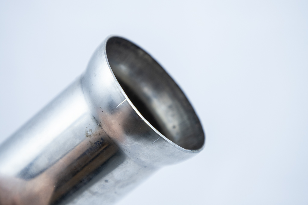
Tube end forming is a metalworking process that reshapes the end of a tube to support functions such as connection, sealing, retention, or feature integration. It involves localized plastic deformation of the tube’s opening using mechanical or hydraulic force, altering its diameter, cross-sectional profile, or terminal shape.
Unlike tube bending, tube end forming does not change the routing of the tube but rather focuses on precision forming at the open end. This technique is widely used in industries such as automotive exhaust systems, hydraulic lines, HVAC ducting, furniture structures, and aerospace fuel lines.
Key Characteristics:
- Processing Area: Limited strictly to the end section of the tube
- Process Type: A plastic deformation technique (cold or hot forming)
- Material Compatibility: Works with low-carbon steel, stainless steel, copper, aluminum, titanium alloys, and even thermoplastics like PP and PVC
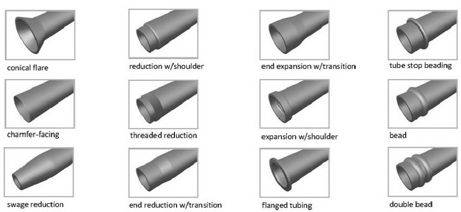
2.0Types and Structural Classifications of Tube End Forming
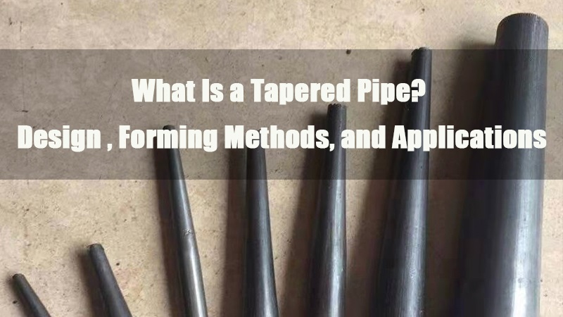
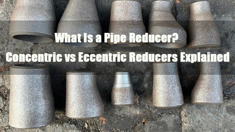
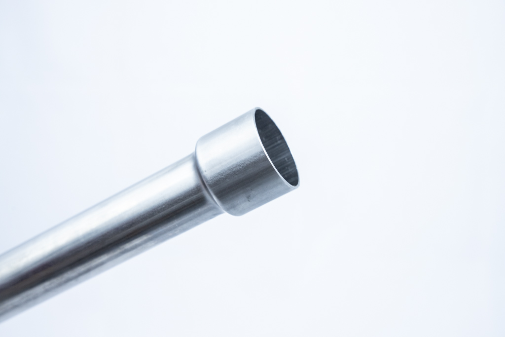
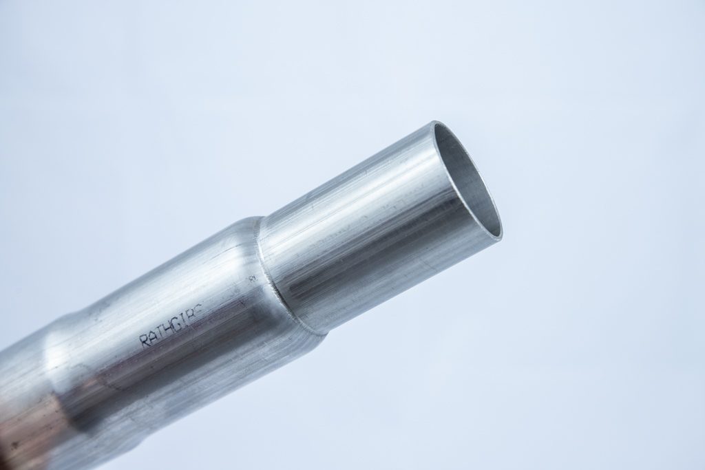
2.1Reduction:
Used for insertion fits, structural stops, or threaded connections.
Common Equipment: Tube End Swaging Machine, Tube Necking Machine
- Shouldered Reduction: A step is formed after reduction, useful for nesting or as a mechanical stop.
- Smooth Reduction: A tapered transition without a defined shoulder, suitable for slip-fit connections.
- Threaded Reduction: The reduced end is machined to form external threads for fitting attachment.
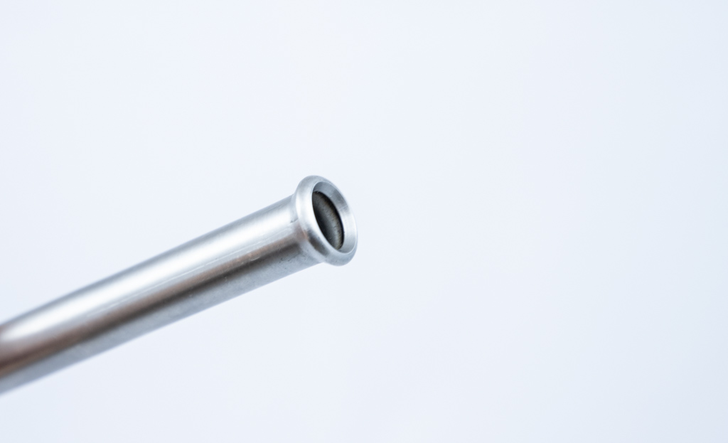
2.2Flaring & Expansion:
Designed to create sealed joints, connect fittings, or enable shape transitions.
Common Equipment: Tube End Flaring Machine, Tube Expanding Machine, Rotary End Forming Machine
- Standard Flare: Typical 37° or 45° flare geometry, widely used in hydraulic and high-pressure fluid systems.
- Shouldered Flare: Flare formation includes a shoulder for added joint stability.
- Bellmouth (20°/37°/45°): Tapered flares for connections with Marmon or SAE fittings.
- Offset Flare: Flare is formed off-center, often seen in irregular components like fuel funnels.
- Spherical Flare: The End of the tube is formed into a dome shape, allowing ball-style socket connections.
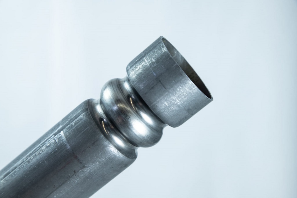
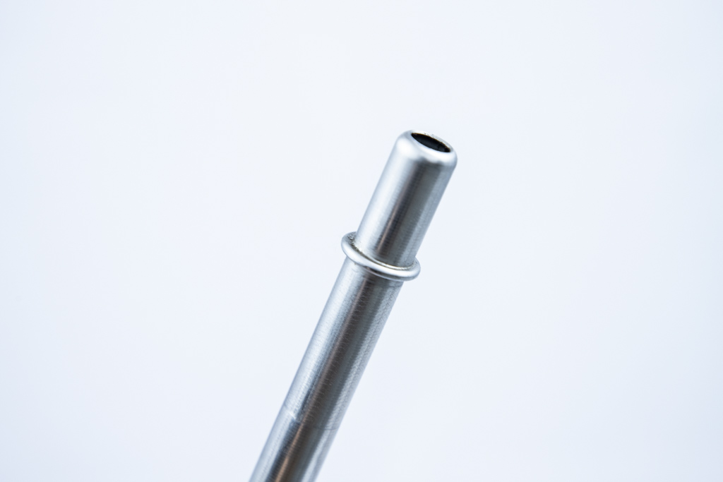
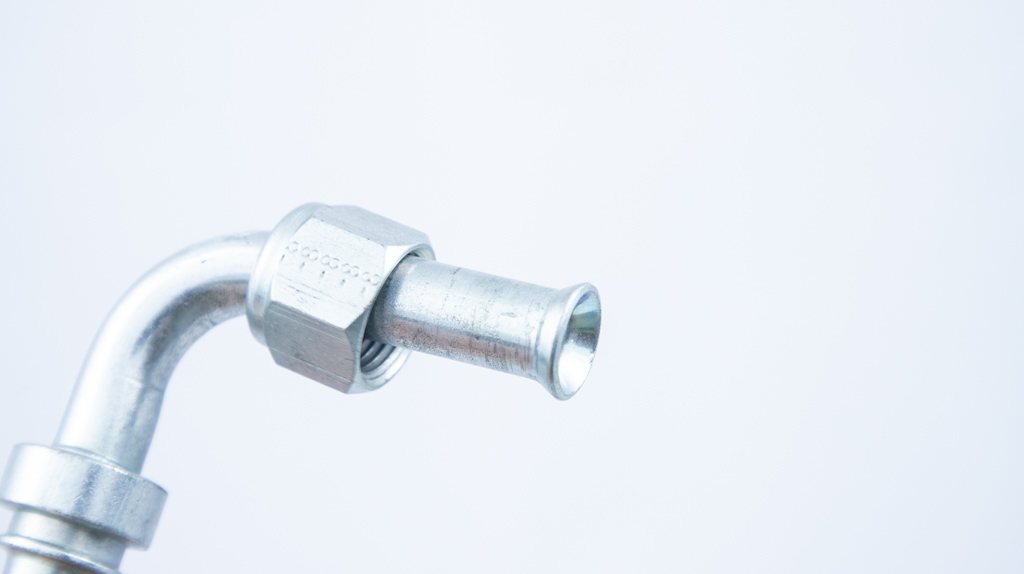
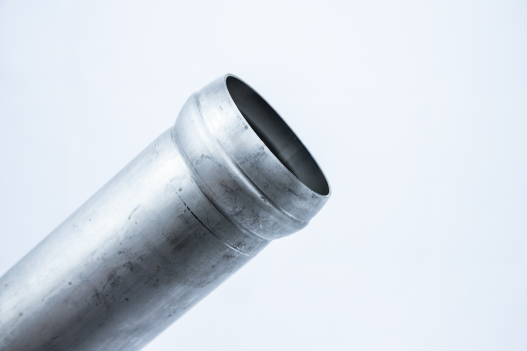
2.3Beading:
Primarily for hose retention, anti-slip, or sealing reinforcement.
Common Equipment: Tube Beading Machine, Rotary Bead Forming Machine
- Single Bead: A circular ridge near the tube end for hose sealing and retention.
- Double Bead: Two parallel ridges that enhance pressure resistance and sealing integrity.
- Inverted Bead: The bead is formed inward into the tube wall, commonly used for locating O-rings or seals.
- Norma Ball / Marmon Bead: Designed for quick-seal connections in automotive exhaust systems.
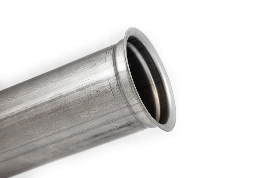
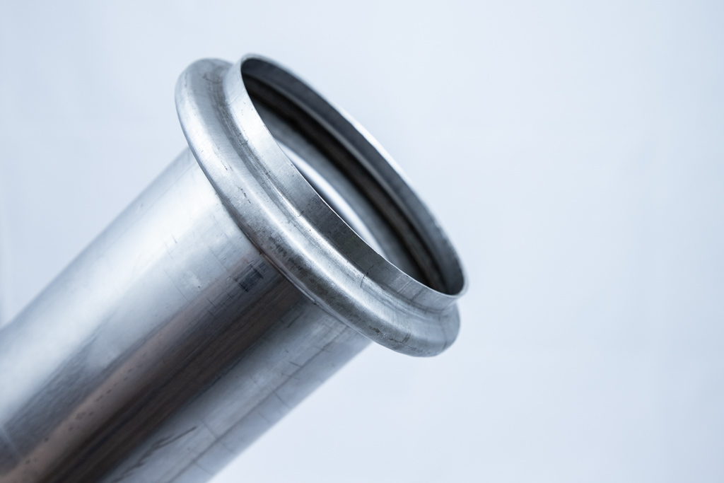
2.4Flanging:
Used to create interfaces for welding, bolted joints, or mechanical assemblies.
Common Equipment: Tube End Flanging Machine, Tube Flare Forming Machine
- 90° Flange: The tube end is flanged outward at a right angle, ideal for welding or clamp connections.
- Conical Flange: Flanged at an angle between 20° and 45°, typically for mating with shaped fittings.
2.5Other End Features:
Support connection, structural reinforcement, or specific functional requirements.
Common Equipment: Rotary End Forming Machine, Tube End Facing and Chamfering Machine
- Chamfered End: Edge of the tube is chamfered to remove burrs and ease insertion.
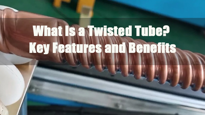
- Knurling: Fine textured pattern on the outer tube surface to improve grip or hose retention.
- Threading: External threads are machined onto the tube end for connection with fittings or valves.
- Slots and Notches: Partial cuts or grooves for positioning, welding, or mating with custom parts.
- Faced Ends: The tube end is precisely squared to ensure sealing or welding flatness.
- Sealing or Stop Features: Rings or bead-like formations used for fluid blocking or insertion depth control.

3.0Detailed Overview of Core Tube End Forming Methods
3.1Flaring:
Process Principle: The tube end is radially expanded using a conical die or mandrel to form a flared structure at a specified angle, improving seal integrity or fitting compatibility.
Process Steps:
① Tube clamping → ② Mandrel or cone insertion → ③ Material expands along the tool → ④ Final flare angle achieved
Common Techniques:
Stamp Flaring: Suitable for standardized flares (e.g., automotive fuel lines); high-efficiency and ideal for volume production
Rotary Flaring: Used for irregular or wide-angle flares (e.g., HVAC, ball-joint seals); more precise forming
Key Parameters:
Typical flare angles: 37° (SAE), 45° (JIS), 90° (high-pressure sealing)
Wall thinning rate should be within 15%; ≤10% for aerospace-grade parts
3.2Reducing / Swaging:
Process Principle: Radial compression of the tube end using dies reduces the outer diameter with a slight increase in wall thickness. Cold-forming thickness increase ≤8%, hot-forming up to 15%.
Typical Applications:
Multi-stage nesting: Common in furniture handrails, telescopic tubes
Nozzle shaping: Used to streamline flow at nozzle entry; typical taper angle is 12°–15°
3.3Flanging:
External Flange: The tube end is bent outward to form a flange surface for bolted or sealed assembly. Flange height typically ranges from 1.2 to 2 times the wall thickness.
Internal Flange: The end is rolled inward to form a groove for an O-ring seal. Groove depth must match the O-ring diameter precisely (tolerance recommended within ±0.05 mm).
3.4Grooving:
Process Principle: Rollers apply pressure to form a symmetrical groove in the tube wall, often used for clamp-type joints or seal placement.
Industry Standards:
NFPA 1963 (Firefighting Hose Coupling): Groove depth 1.2±0.1 mm, width 2.0±0.2 mm
Three-roller machines achieve ±0.05 mm accuracy; better than single-roller systems (±0.15 mm)
Design Notes:
Minimum groove root radius should be ≥0.3×wall thickness to avoid stress concentration and cracking
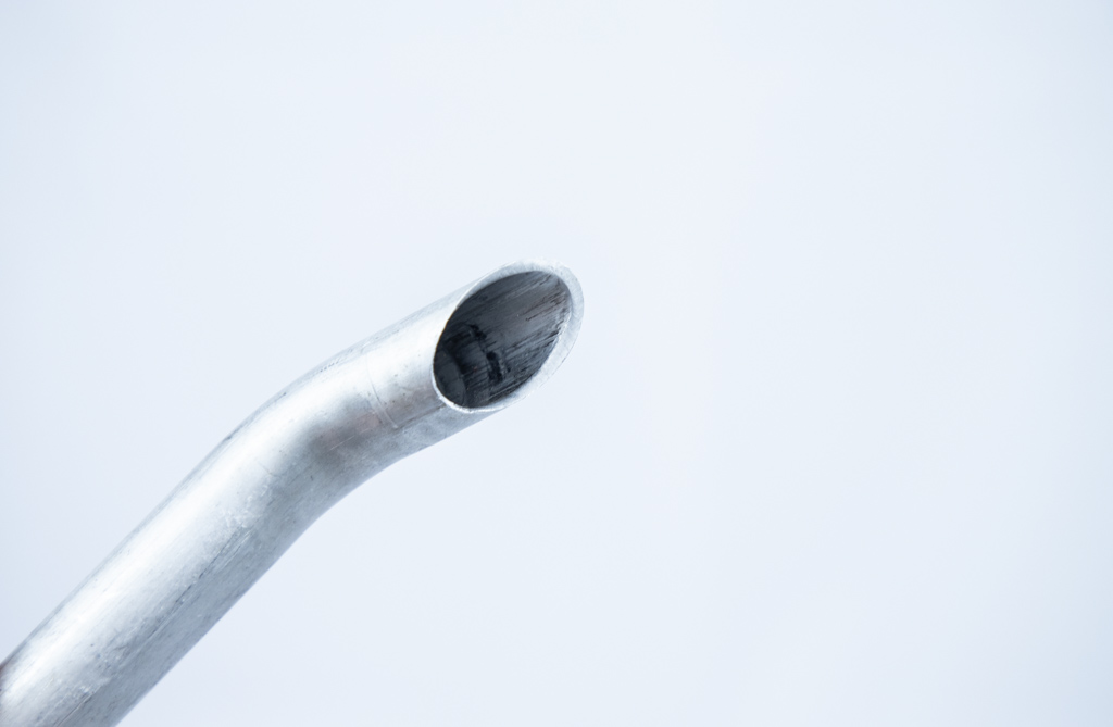
3.5Auxiliary Forming Techniques
End Bending: A slight bend of 15°–30° at the tube end, typically used for exhaust routing or clearance adjustments.
Flattening & Closing: Tube end is flattened and sealed using dies; often used in furniture legs or display structures. Flattening length should be at least 3× tube diameter for adequate strength.
Chamfering & Deburring: Tube ends should be chamfered to prevent damage to seals or stress buildup. Recommended angle: 45°; depth: 0.2–0.5 mm.
3.6Key Differences Between Tube End Forming and Tube Bending
Definition Perspective:
Tube End Forming: Focuses on altering the geometry of the tube’s open end through localized plastic deformation. This process reshapes the diameter, cross-section, or terminal features to support functions such as connection, sealing, positioning, or integration.
Tube Bending: Alters the overall path or shape of the tube, creating curves or angular deflections. The primary goal is to change the routing of the tube to suit installation or spatial layout requirements.
Forming Area:
Tube End Forming: Acts only on the localized end section of the tube, typically within a few millimeters to centimeters from the opening. The forming is tightly controlled to produce functional end features.
Tube Bending: Applies to any section along the tube’s length, altering its spatial orientation. It generally involves longer segments and affects the entire routing of the tube.
Purpose and Functional Differences:
Tube End Forming: Aims to improve the connection performance of the tube end. Common goals include:
- Flaring for insertion and sealing
- Reducing for mating and stops
- Flanging for bolted or welded connections
- Grooving for clamp placement
These features enhance sealing, leak prevention, alignment, and structural reinforcement.
Tube Bending: Intended to redirect the tubing path and fit the installation environment. It helps avoid obstructions and supports complex spatial configurations.
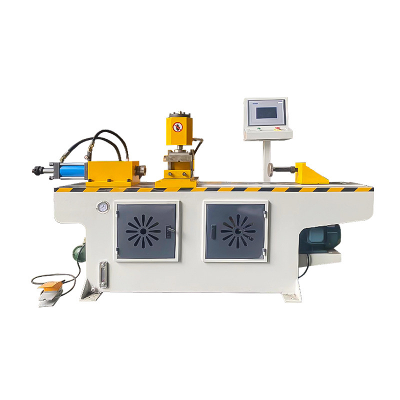
4.0What Is a Tube End Forming Machine?
A tube end forming machine is a piece of equipment designed to perform shaping operations—such as compression, flaring, reducing, flanging, chamfering, rolling, and closing—on the open ends of tubes. Its primary goal is to improve sealing performance, connection reliability, and structural strength at the tube end.
Common Forming Methods
| Forming Method | Description |
| Flaring | Expands the tube end into a bell shape for easier insertion and sealing. |
| Reducing | Narrows the tube end diameter for mating with smaller components. |
| Beading | Forms a raised flange or bead at the tube end to enhance strength or accommodate sealing rings. |
| Chamfering | Removes burrs to smooth the tube edge and facilitate assembly. |
| Closing | Seals the tube end, commonly used in exhaust systems or fluid containment. |
| Grooving | Creates circumferential grooves or corrugations for mechanical joints or sealing purposes. |
Main Structural Components
- Machine Frame and Bed: Supports the entire system and ensures operational stability.
- Forming Dies: Custom-made according to specific processes, determining the final tube shape.
- Hydraulic or Servo System: Provides precise forming or clamping force.
- Clamping Unit: Secures the tube in place during forming to prevent displacement.
- Control System (PLC or Touch Panel): Enables programmable control and parameter setting.
Classification Methods
By Drive Mechanism
- Hydraulic Tube End Forming Machine:
Offers high thrust; suitable for forming high-resistance materials such as thick-wall steel or stainless steel. Capable of complex operations like flaring, reducing, beading, and grooving. Commonly used in automotive exhaust and industrial piping systems. - Pneumatic Tube End Forming Machine:
Simple structure and fast response; ideal for quick processing of small-diameter, thin-wall tubes. Frequently used for lightweight components and laboratory tubing. - Servo Electric Tube End Forming Machine:
High forming precision, responsive control, and low energy consumption. Supports high repeatability and is suitable for automated lines and precision manufacturing.
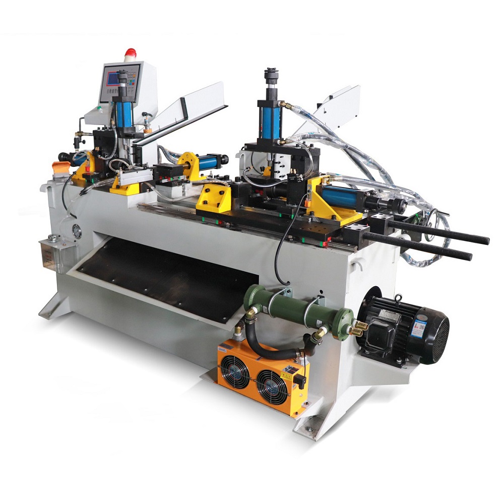
By Number of Workstations
- Single-Station Machines:
Compact design for a single forming process such as flaring, reducing, or closing. Suitable for small-batch jobs or modular production steps. - Dual-Station Machines:
Capable of performing two consecutive operations (e.g., reducing + beading, flaring + grooving). Offers a balance between compact layout and production efficiency. - Multi-Station Machines:
Supports three or more forming steps in sequence (e.g., reducing + flaring + grooving + closing) with a single setup. Enhances automation and output, ideal for high-volume and complex part production.
By Automation Level
- Manual Machines: Low-cost and simple construction. Requires manual loading and operation. Suitable for prototyping, repair work, or temporary lab use.
- Semi-Automatic Machines: Core forming actions are automated; manual loading/unloading is still required. Offers a balance between cost and efficiency for low to medium production volumes.
- Fully Automatic Machines: Equipped with automatic feeding, positioning, and die-changing systems. Can operate standalone or be integrated into automated lines for unattended, continuous processing—ideal for high-volume production.
5.0Tube End Forming – Frequently Asked Questions (FAQ)
What’s the difference between tube end forming and tube bending?
Tube end forming focuses on shaping the open end of the tube without altering its overall path. Tube bending, on the other hand, changes the tube’s shape and routing.
What are the common types of tube end forming?
Typical types include reduction, flaring and expansion, beading, flanging, and additional features like chamfering, knurling, and threading.
What are the standard flare angles used in flaring?
Common flare angles include 37° (SAE standard), 45° (JIS standard), and 90° (used for high-pressure sealing). Each angle serves different sealing and connection purposes.
What are typical applications of the reducing process?
Reduction is mainly used for slip-fit connections, multi-stage nesting, and nozzle shaping. It reduces the tube’s end diameter, often with a slight increase in wall thickness.
What’s the difference between flaring and flanging?
Flaring involves bending the tube end outward to create a joining surface, often for welding or bolted assembly. A flange is a more standardized flared shape designed for structured sealing and installation.
What is the primary purpose of grooving?
Grooving forms a recess in the tube wall to hold clamps or locate sealing rings, improving joint security and sealing performance.
References
gjsteel.com/capabilities/tube-end-forming
proto1mfg.com/2021/07/27/tube-end-forming-types-of-tube-end-forming
www.rs-traut.de/en/products/tube-forming