- 1.0What Is a Press Brake?
- 2.0“Press Brake” vs “Brake Press”: What’s the Difference?
- 3.0How a Press Brake Works
- 4.0Why Is Metal Suitable for Bending? What Is a Press Brake Used For?
- 5.0Main Components of a Press Brake
- 6.0Brief Process of Press Brake Operation
- 7.0Common Types of Press Brake
- 8.0What Is NC Press Brake (Numerical Control Press Brake)?
- 9.0What Is CNC Press Brake (Computer Numerical Control Press Brake)?
- 10.0What Are the Main Differences Between NC and CNC Press Brakes?
- 11.0What Are the Drive Methods for Press Brakes?
- 12.0How to Set up a Press Brake?
- 12.1Step 1: Review the Workpiece Drawing
- 12.2Step 2: Select the Appropriate Bending Method and Tooling
- 12.3Step 3: Calculate the Required Bending Force (Tonnage)
- 12.4Step 4: Install and Adjust Tooling (Clamping the Dies)
- 12.5Step 5: Configure Backgauge System
- 12.6Step 6: CNC System Programming and Validation (CNC Press Brake)
- 12.7Step 7: Save the Setting and Begin Operations
- 12.8Bending machine working process diagram:
- 13.0Comparison of Different Types of Press Brakes
- 14.0Factors to Consider When Choosing a Press Brake
- 15.0Applications of Press Brakes
- 16.0Common Press Brake Failures and Solutions
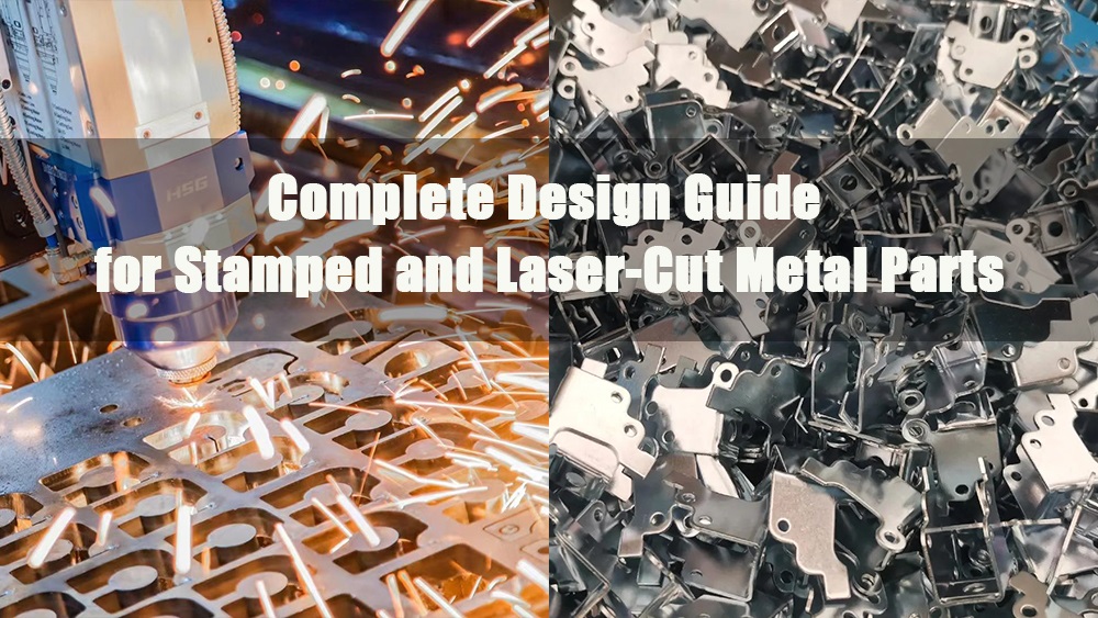
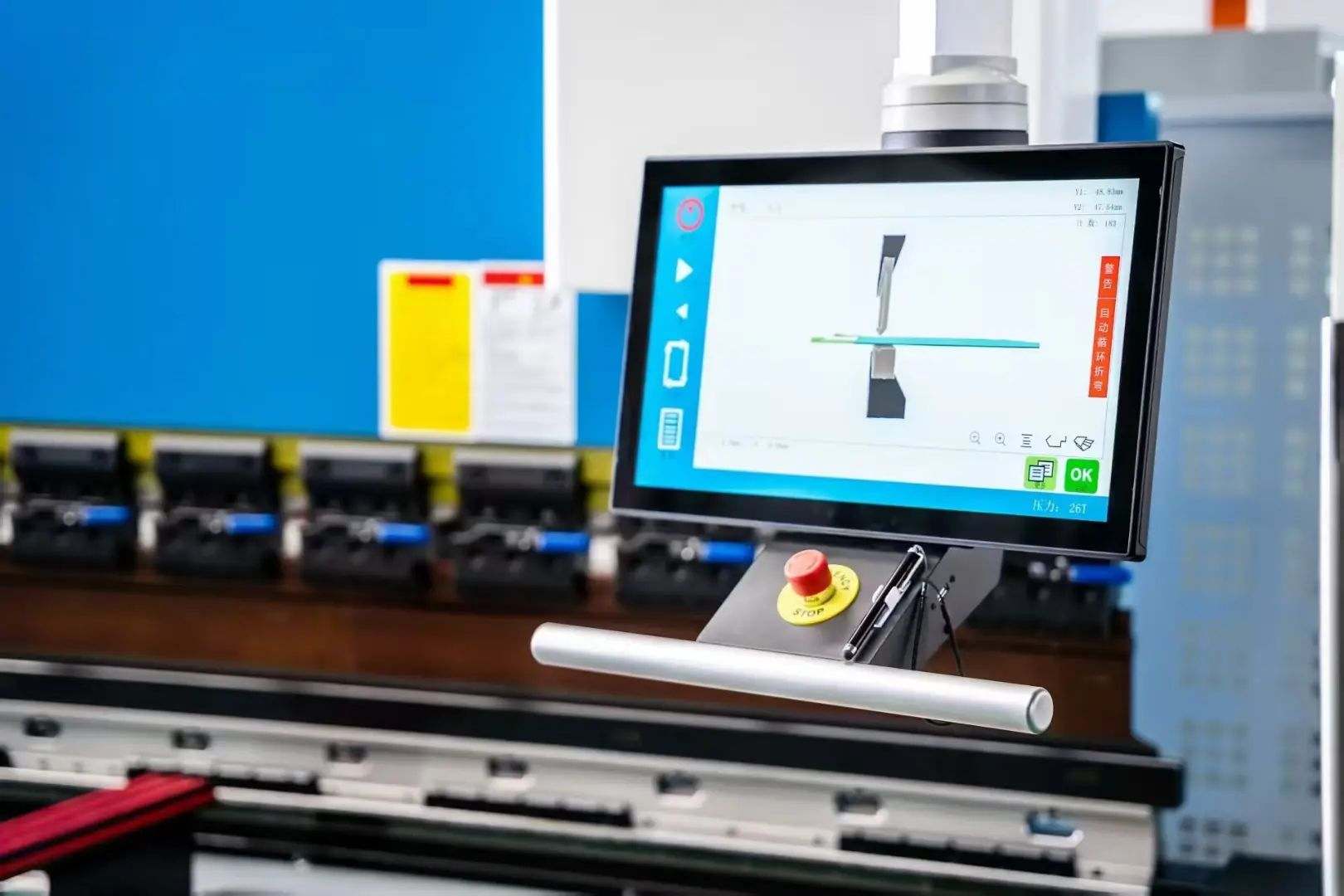
1.0What Is a Press Brake?
A press brake is a metal forming machine used to bend sheet metal into a specified angle or shape. It’s widely used in sheet metal fabrication and structural manufacturing. The main principle involves applying concentrated pressure to the bending line of the metal sheet, causing it to undergo plastic deformation.
During the bending process, the metal sheet is placed on the lower die, while the upper punch moves downward under pressure, forcing the sheet into the die’s profile. The shape of the punch and die correspond to each other, allowing the metal to be formed accurately along the die’s contour. By adjusting the stroke of the punch and the pressure applied, a range of bending angles, radii, and lengths can be achieved.
In simple terms, press braking is a precise and controllable metal forming process that efficiently transforms flat metal into complex forms by applying force with a punch and a die.
.jpg)
2.0“Press Brake” vs “Brake Press”: What’s the Difference?
In metalworking, “press brake” typically refers to a machine used to bend metal sheet into a predefined angle or shape. This process involves placing the workpiece between a punch (the upper tool) and a die (the lower tool) and applying pressure until the sheet deforms permanently. These press brakes are widely used in industrial production due to their high precision, repeatability, and versatility — making them a preferred solution for a range of complex bending applications.
Sometimes, however, the term “press brake” is used more broadly to describe various types of bending equipment, including:
High-precision electric or hydraulic press brakes: Ideally used for industrial production requiring high accuracy, speed, and automation.
Simple manual press brakes: Designed for small batches, thin materials, or prototyping. While they may enable a degree of precision, their functionality and automation are limited.
This semantic variation typically results from different usage scenarios or industry terminology. In technical documents, it’s recommended to distinguish between electric press brakes, hydraulical press brakes, or manual press brakes to avoid confusion.
3.0How a Press Brake Works
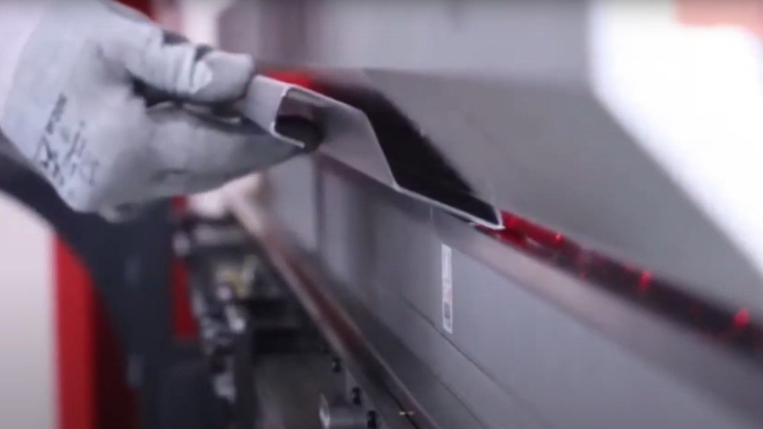
The press brake’s main working principle is to apply pressure through a punch and a die, forcing the metal sheet to undergo plastic deformation along a predetermined bending line. Here’s how it typically works:
The metal sheet is placed into the V-shaped groove of the lower die. The upper punch then descends vertically under hydraulic or servo control,pressing the metal into the groove. As the punch moves down, the sheet deforms along the edges of the die, ultimately forming the desired bend.
By changing the shape or size of the punch and die, press brakes can produce a wide range of bending angles and profiles — meeting the demands of complex sheet metal components.
4.0Why Is Metal Suitable for Bending? What Is a Press Brake Used For?
One of metal’s key properties is its relatively high ductility — its ability to be stretched and formed without fracturing. This makes metal a flexible material for a wide range of applications. During the manufacturing process, metal sheets typically start in flat or strip form, but often need to be reshaped before their final use.
This is where metal forming equipment comes into play — and the press brake stands out as one of the most important and versatile tools in the industry.
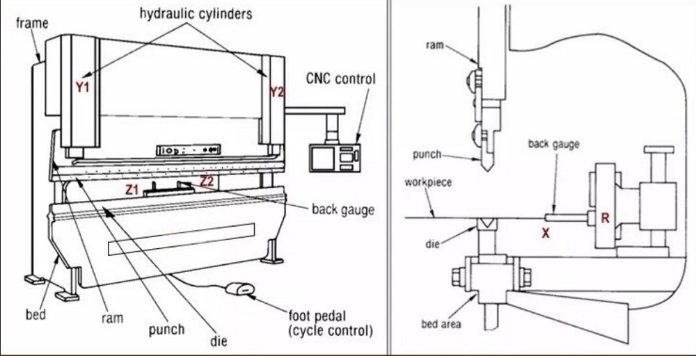
5.0Main Components of a Press Brake
- Frame:The main structure of the press brake, typically welded from high-strength steel. It provides exceptional rigidity and load-bearing capacity, ensuring stability and precision during the bending process.
- Ram / Slide:Mounted on the upper beam, the ram drives the punch up and down. During bending, it applies pressure to the metal sheet, causing it to undergo plastic deformation.
- Punch & Die:The punch forms the upper tool and is attached to the ram, while the die is installed on the worktable. The metal sheet is placed in between, and under pressure from the punch, it is forced into the die’s groove, forming the desirable shape. Different sizes and profiles of punches and dies can be swapped to accommodate various bending requirements.
- Worktable / Bed:The worktable, located at the base of the press brake, serves as a platform for supporting both the die and the metal sheet during bending. Often, it includes a V-shaped groove to aid in forming a range of bends.
- Hydraulical or Servo System:The hydraulic or servo drive provides the force needed to move the ram. Traditional machines typically use hydraulic cylinders to generate high pressure, while high-end models employ servo-electric drives for greater precision, energy efficiency, and control.
- Back Gauge:Mounted at the rear of the bending area, the back gauge helps position the metal sheet accurately, ensuring each bend is consistent and repeatable.
6.0Brief Process of Press Brake Operation
- Material Placement:Placement of the metal sheet flatly on the worktable, with the back gauge used for accurate positioning.
- Tool Selection:Selecting a matching set of punch and die according to the bending angle and profile of the workpiece.
- Clamping and Preparation:Once the sheet is in place, it is clamped by the die and punch to avoid any movement during bending.
- Bending Action:The ram moves down, forcing the punch into the V-shaped groove of the die. This forms the metal to the predetermined bending angle.
- Return and Release:After bending, the ram moves back up to its starting position, relieving pressure on the metal sheet.
- Part Removal:The clamping is opened, and the operator removes the finished, formed workpiece — ready for the subsequent processing or production step.
7.0Common Types of Press Brake
The press brake can be classified into six main types based on its drive and control method: mechanical press brake, hydraulic press brake, electro-hydraulic press brake, pneumatic press brake, servo press brake, and CNC press brake. Here’s a brief introduction and pros and cons for each:
Mechanical Press Brake:
The mechanical press brake drives the ram up and down using a flywheel and a clutch-controlled gear rotation.
Pros:
- Simple structure, easy operation, and low maintenance cost
- Ability to process materials exceeding rated tonnage in some cases
Cons:
- Difficult to control bending speed with precision
- Lower bending accuracy and poor repeatability
- Less safe; not recommended for complex operation
Hydraulical Press Brake:
The hydraulic press brake utilizes two hydraulic cylinders instead of a traditional mechanical transmission.
Pros:
- Large bending force, suitable for heavy-duty plate processing
- Higher precision for fine bending operations
- Better control over movement, allowing multiple bending segments
Cons:
- Complex structure requiring higher technical expertise
- Higher maintenance cost; failure of components can cause significant downtime
- Possible risk of hydraulic fluid leaks
- Operations must be kept within rated tonnage
Electro-Hydraulic Servo Press Brake:
The electro-hydraulic press brake is a smart, high-precision CNC bending machine with electro-hydraulic control.
Principle of operation:
- Left and right hydraulic cylinders are controlled by separate servo motors
- Displacement sensors enable real-time monitoring of ram position
- CNC controls coordinate both cylinders to maintain parallelism and precision
Pros:
- ±0.01 mm high-precision and strong repeatability
- Energy-saving and environmentally friendly — oil delivery on-demand with no leaks
- Intelligent functionality — supports graphical programming, angle compensation, automated adjustment, etc.
- Reliable — maintains stability during long production runs
Cons:
- Higher initial investment
- Requires advanced technical expertise for maintenance
Pneumatic Press Brake:
The pneumatic press brake utilizes compressed air to drive the ram instead of a hydraulic or mechanical system.
Pros:
- Simple structure with faster response
- Flexible control — easy start-up or shutdown
- Clean and environmentally friendly — no liquid leaks
Cons:
- Limited bending force — unsuitable for thick plate or heavy-duty applications
- Lower bending accuracy than hydraulic systems
Servo Electric Press Brake:
The servo electric press brake is powered by a servo motor instead of cylinders.
Pros:
- Higher bending precision and repeatability
- Quiet operation with low energy consumption
- Oil-free — lower maintenance and environmentally clean
- Suitable for applications requiring high clean standards
Cons:
- Limited bending force — mainly for small tonnage or lightweight applications
- Higher initial investment
The CNC press brake is a fully automated machine combining hydraulic or servo drives with computerized controls for high-precision, high-efficiency bending.
Features:
- Fully automated control with high accuracy and low error
- Programmable for complex bending operations
- Higher production efficiency with reduced labor costs
- Applicable to industries such as aerospace, automotive, electronics, and construction
⚡Note: “CNC” refers to a control method, not a separate drive form; CNC can be integrated with hydraulic, electro-hydraulic, or servo systems.
8.0What Is NC Press Brake (Numerical Control Press Brake)?
Definition:The NC press brake is a numerical control machine, typically featuring a simplified keypad or PLC control system. The synchronization of the ram’s movement is mechanically powered by a torsion bar, making it a convenient choice for medium or low-precision bending tasks.
Structural Features:
- The two cylinders are connected by a torsion bar to keep their movement synchronized.
- The cylinders drive the ram up and down to perform bending.
- The control system is simplified — normally it only controls backgauge (X-axis) and ram (Y-axis) positions.
Pros:
- Lower cost and simpler operation
- Suitable for small and medium enterprises with less-demanding precision requirements
Cons:
- Synchronization depends on mechanical components — the torsion bar may deform over time
- Incapable of real-time error detection or correction
- Limited ability for complex programming and mult-step operations
9.0What Is CNC Press Brake (Computer Numerical Control Press Brake)?
Definition:The CNC press brake is a high-performance bending machine that integrates a computerized control system with hydraulic, electro-hydraulic, or servo drives. It can perform fully automated, high-precision, and high-efficiency bending operations for sheet metal.
Control Method:
- Controlled by industrial-grade computing systems (such as Delem, ESA, or Cybelec)
- Real-time monitoring of ram (Y1/Y2) and backgauge (X, R, Z) positions
- Allows multi-step programming with graphical interfaces, angle compensation, and error detection
Drive System Support:
- Hydraulical (conventionally or electro-hydraulical)
- Purely servo (electric press brake)
Bending Type Support:
- Downward pressure (common): ram moves down while table is fixed
- Upward pressure (uncommon): table moves upward while ram is fixed
Pros:
- High precision (±0.01 mm) with repeatable bending
- Ability to calculate bending sequence, angle, and compensation
- Flexible programming — suitable for large batches and complex operations
- High production efficiency with fast setup and changeover
- Support for remote programming and Industry 4.0 integration
10.0What Are the Main Differences Between NC and CNC Press Brakes?
| Item | NC Press Brake | CNC Press Brake |
| Control System | Simple numerical controller (push-button) | Industrial computer with graphical control |
| Synchronization | Mechanically synchronized by torsion shaft | Hydraulically or servo-controlled synchronization |
| Accuracy | Medium; larger deviations | Higher precision; automatic error correction |
| Programming Complexity | Supports only simple operations | Supports complex process programming |
| Degree of Automation | Low | High |
| Applications | General sheet metal processing | Large-batch, high-demand, custom bending |
| Cost | Lower | Higher |
11.0What Are the Drive Methods for Press Brakes?
When bending metal plate, significant pressure is usually needed to produce plastic deformation. This pressure is called press tonnage — the maximum force a press brake can apply during its operation. The greater the tonnage, the thicker or longer the metal plate that can be processed.
To generate and transmit this force, press brakes typically employ various drive methods, including:
- Hydraulical Drive (commonly used in CNC press brakes):
Utilises a hydraulic system to generate high tonnage — ideal for thick plate and heavy-load bending. This is the most frequently used method in industry. - Servo Electric Drive:
Uses a servo motor for precise control of ram movement, offering high accuracy and fast response — perfect for applications requiring high precision and energy efficiency. - Pneumatic Drive:
Powered by compressed air; simple in structure — suitable for small to medium tonnage and faster operations. - Mechanical Drive:
Operated by flywheel and clutch mechanisms; a traditional structure — ideal for heavy-duty, high-frequency production.
Usually, the name of the press brake reflects its drive method, for example: hydraulic press brake, pneumatic press brake, or servo electric press brake.
12.0How to Set up a Press Brake?
Before starting bending operations, proper press brake setup is crucial for ensuring bending accuracy, extending tool life, and maintaining operational safety. The following standard procedure applies to both NC and CNC press brakes.
12.1Step 1: Review the Workpiece Drawing
- Confirm material properties: material (such as carbon steel, stainless steel, or aluminum) and yield strength.
- Confirm geometric dimensions: plate thickness, length, bending angle, bending radius.
- Identify design requirements, including:
- Flanze length
- Bending direction (inner or outer)
- Tolerance requirements
- Whether deburring or leveling is needed after bending
12.2Step 2: Select the Appropriate Bending Method and Tooling
Bending Method (According to Accuracy and Force Requirements):
| Method | Characteristics | Accuracy | Tonnage |
| Air Bending | Common; low tool wear | Medium | Standard |
| Bottom Bending | Material fully seats into die | Higher | Air bending ×4–6 |
| Coining | Material is completely forced into die corner | Highest | Air bending ×8–10 |
Tool Selection Recommendations:
- Punch/Upper Tool: Should match plate thickness and bending angle to avoid damage or overloading.
- Die/Lower Tool: The die opening is typically 6–12 times the plate thickness.
- Material Matching: The tool material should be equal to or greater in hardness than the plate material.
12.3Step 3: Calculate the Required Bending Force (Tonnage)
Use tonnage charts provided by the manufacturer or specialized software.
Take into account the following parameters:
- Thickness (t)
- Width (L)
- Material’s strength
- Die opening (V)
Reference:
- Air bending pressure = base pressure
- Bottom bending pressure = air bending pressure × 4–6
- Coining pressure = air bending pressure × 8–10
⚡ Avoid exceeding the rated tonnage to enable safe operation.
12.4Step 4: Install and Adjust Tooling (Clamping the Dies)
- Inspect for tool wear and uniform thickness.
- Install the upper and lower dies and lock them in place.
- Adjust ram stroke to appropriate upper and lower limits to avoid collision.
- Set up reserved resting positions for special applications, if needed.
- Align the center of the tool and the worktable.
12.5Step 5: Configure Backgauge System
- Set backgauge (X, R, Z) positions and heights.
- Enter bending sequence and parameters according to the drawing.
- If there are multiple operations, enable interference checks (CNC) to avoid collision.
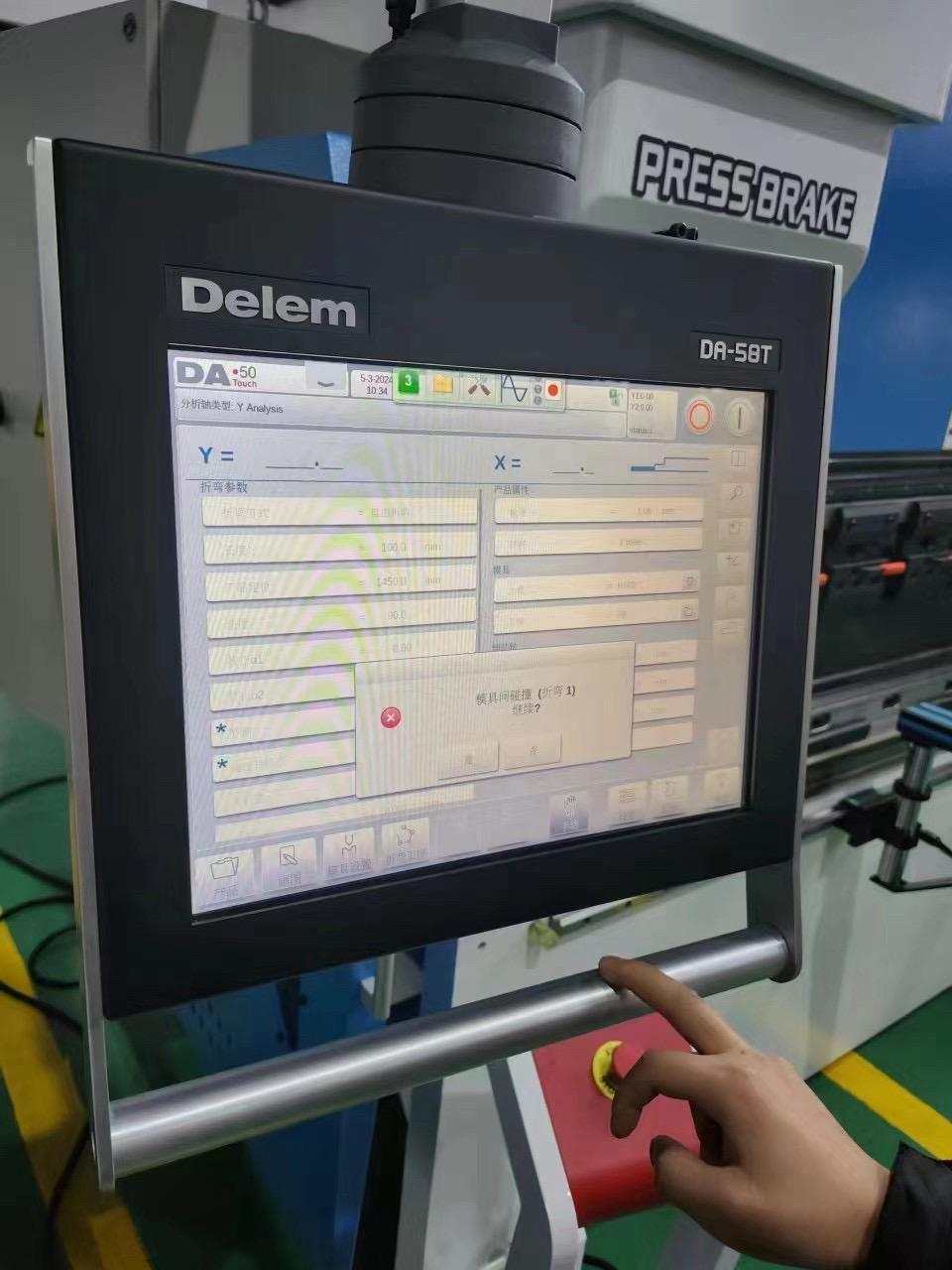
12.6Step 6: CNC System Programming and Validation (CNC Press Brake)
- Become familiar with control panel (Delem, ESA, Cybelec, etc.).
- Input or import bending programs (thickness, material, angle, tool number).
- Perform offline programming (optional) to preview bending path.
- Test with scrap material to validate bending angle, springback, interference, and other parameters.
- Adjust the program based on trial results if needed.
12.7Step 7: Save the Setting and Begin Operations
- Save the bending program to reuse in future production.
- Check safety mechanisms, emergency stop, and related controls.
- Begin mass production and periodically inspect bending angle and dimensions during the process.
12.8Bending machine working process diagram:

Analyze drawing → Select bending method and tools → Calculate bending tonnage → Install and align tooling → Set backgauge → CNC programming and trial bending → Save settings and start production.
13.0Comparison of Different Types of Press Brakes
| Type | Drive Method | Accuracy | Force | Application | Advantages | Disadvantages |
| Mechanical Press Brake | Flywheel | Low | Medium | General sheet metal processing | Simple operation, easy maintenance | Poor control, low accuracy, poor safety |
| Hydraulical Press Brake | Hydraulical cylinder | High | High | Thick plate and large components | Large force, strong control | Complex structure, prone to leaks |
| Electro-Hydraulical Press Brake | Electric-hydraulical servo cylinder | Very high | High | Automated and precision bending | High precision, energy-saving, environmentally friendly, and automated control | Higher cost, complex system |
| Pneumatic Press Brake | Air pressure | Medium | Low | Light-load sheet metal processing | Fast, clean, environmentally friendly | Limited force, not for thick plate |
| Servo Press Brake | Electric servo drive | High | Low | Precision, light-load applications | High precision, low noise, energy-saving | Limited force, higher cost |
| CNC Press Brake | CNC control + multiple drives | Very high | Varies by drive | Automated processing across industries | Automated, accurate, and efficient | Higher cost, dependency on programming and maintenance |
14.0Factors to Consider When Choosing a Press Brake
- Material Type and Thickness: Different materials have different bending properties. Aluminum bends more easily, while stainless steel requires greater force. The thickness also directly impacts the required tonnage — make sure the machine’s force capacity is sufficient.
- Bending Capacity: This includes maximum bending force and effective bending length. Force controls whether thick or high-strength materials can be processed, while length controls the size of the workpiece in a single bending operation.
- Bending Accuracy and Repeatability: Accuracy refers to whether the bending angle is correct, and repeatability assesses whether subsequent bends are consistent. Higher-precision applications typically require CNC machines.
- Production Rhythm and Capacity: According to production volume and production pace, a more stable and efficient machine should be selected for high-frequency and large-batch applications.
15.0Applications of Press Brakes
- Automotive Industry: Used to produce brackets, chassis components, body panels, and exhaust systems — high precision guarantees conformity to stringent standards and helps improve vehicle quality and safety.
- Aerospace Industry: Processes high-performance materials, like aluminum and titanium alloys, for aircraft frames, wing components, and engine casings — requiring high precision and reliability.
- Home Appliances: Used in the manufacturing of refrigerator panels, washing machine casings, air conditioning components, etc. — high precision and flexibility enable components to closely match their design.
- Construction Industry: Processes structural components for buildings, metal plate structures, and ornamental elements — useful in structural, architectural, and roofing applications.
- Furniture Manufacturing: Bends metal sheets to create furniture frames, brackets, and ornamental components — adding both structural appeal and functionality.
- Medical Equipment: Processes metal components for surgical instruments, diagnostic equipment, and hospital furniture — meeting stringent precision and sanitary standards.
- Electronic and Electrical Equipment: Used for manufacturing control cabinets, brackets, and casings — ensuring structural stability and operational safety.
- Defense Industry: Processes metal for armored plate structures, military equipment casings, and ammo storage containers — meeting high-strength and shock resistance standards.
16.0Common Press Brake Failures and Solutions
| Fault Condition | Possible Causes | Solutions |
| Hydraulical pressure is missing or insufficient | 1. Incorrect rotation direction of motor or pump 2. Clogging of pressure relief valve 3. Electromagnet valve sticking 4. Leakage in pressure control valve | 1. Check motor and pump rotation direction 2. Clean pressure relief valve 3. Repair or clean electromagnetic valve 4. Repair or replace pressure control valve |
| Slider drops slowly or unstably | 1. Oil cylinder wear 2. Guide rail wear or poor synchronization 3. Low hydraulic oil level 4. Fast feed speed set too high 5. Filling valve sticks or fails to open | 1. Inspect cylinder seals 2. Repair guide rail 3. Refill hydraulic oil 4. Reduce fast feed speed 5. Clean filling valve |
| Hydraulical oil leaks | 1. Loose pipeline connection 2. Seals worn or damaged | 1. Tighten pipeline connection 2. Replace seals |
| Bending is uneven on both sides | 1. Uneven die wear 2. Upper die is not parallel | 1. Adjust die height or replace die 2. Align or adjust upper die |
| Large noise | Connection is loose, bearings worn, or components damaged | Check and tighten connections; replace faulty components or die |
| Electrical control abnormalities | Connection is loose, sensor fails, or circuit board is faulty | Check connection points; replace sensor or repair control board |
| Machine overheating | Radiator is clogged or cooling system faulty | Clean radiator; check and repair cooling loop |
| Slider cannot slowly lower or bending force is insufficient | 1. Directional valve (such as 4/2 valve) faulty 2. Filling valve sticks | 1. Inspect or replace directional valve 2. Clean filling valve |
| Return speed is slow and pressure is high | Filling valve is not fully opened | Check whether the filling valve is fully opened |
References
www.ursviken.com/what-is-a-press-brake-used-for/
www.adhmt.com/how-does-a-press-brake-work/
www.epowermetals.com/metal-forming-and-welding-glossarymetal-forming-and-welding-glossary.html
https://www.alekvs.com/press-brake-machine/