- 1.0What Is a Pipe Reducer?
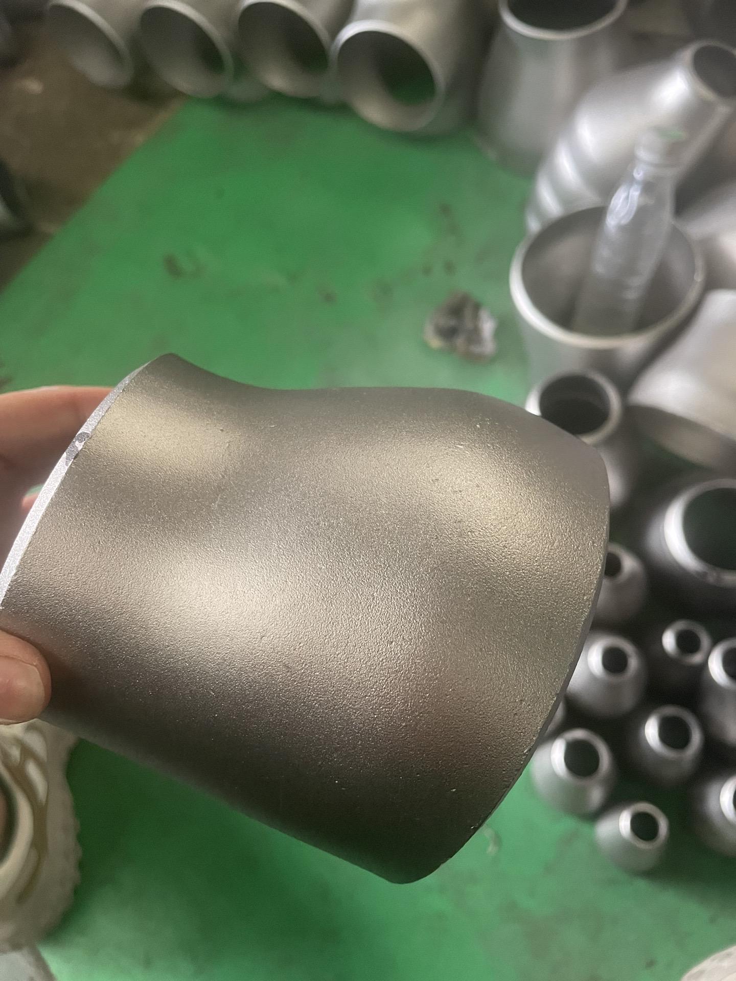
- 2.0What Is a Concentric Reducer?
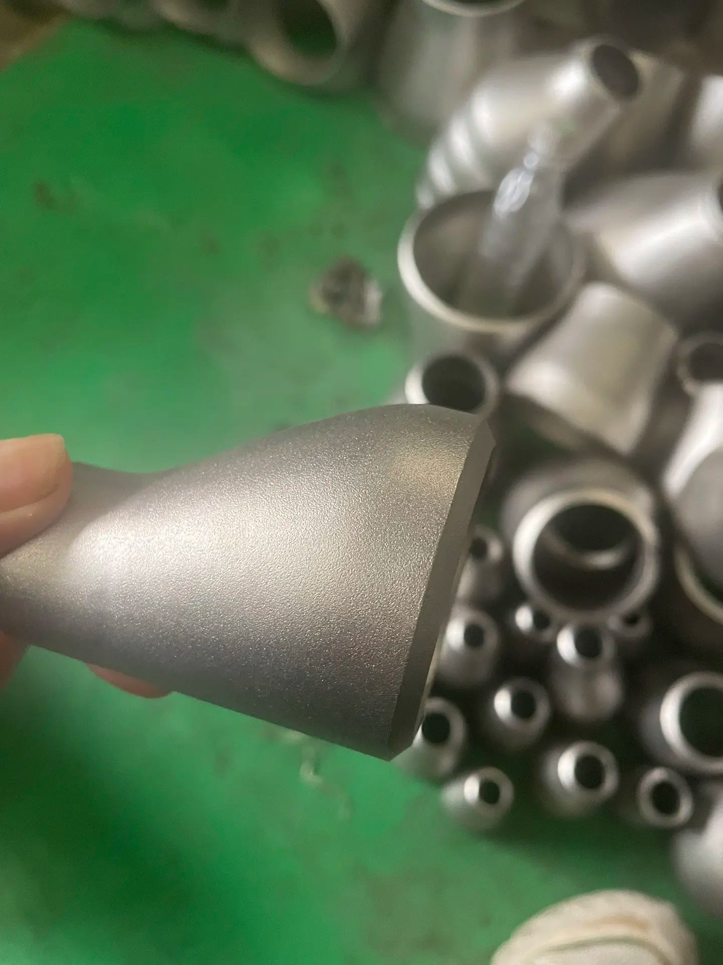
- 3.0What Is an Eccentric Reducer?
- 4.0Concentric vs. Eccentric Reducer: Key Differences in Structure and Application
- 5.0Comparison Table: Concentric vs. Eccentric Reducer
- 6.0When to Use a Concentric Reducer
- 7.0When to Use an Eccentric Reducer
- 8.0How to Choose: Concentric vs. Eccentric Reducer
- 9.0Standard Dimensions of Concentric Reducers (ASME B16.9)
- 10.0Typical Dimensions of Eccentric Reducers (ASME B16.9)
- 11.0Manufacturing Processes & Equipment for Pipe Reducers
- 12.0Pipe Reducer Standards and Dimensional Specifications
- 13.0Pipe Reducer Installation Methods and Key Considerations
- 14.0Applications of Pipe Reducers
- 15.0Common Materials Used for Pipe Reducers
- 16.0Conclusion
- 17.0Common FAQs about Pipe Reducers
1.0What Is a Pipe Reducer?
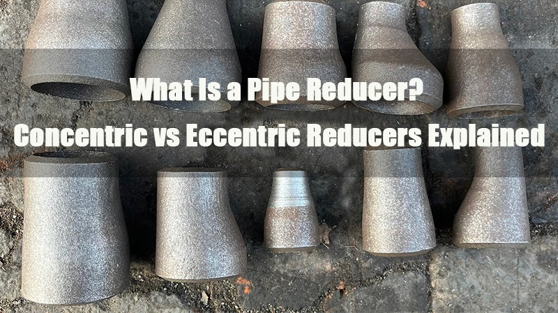
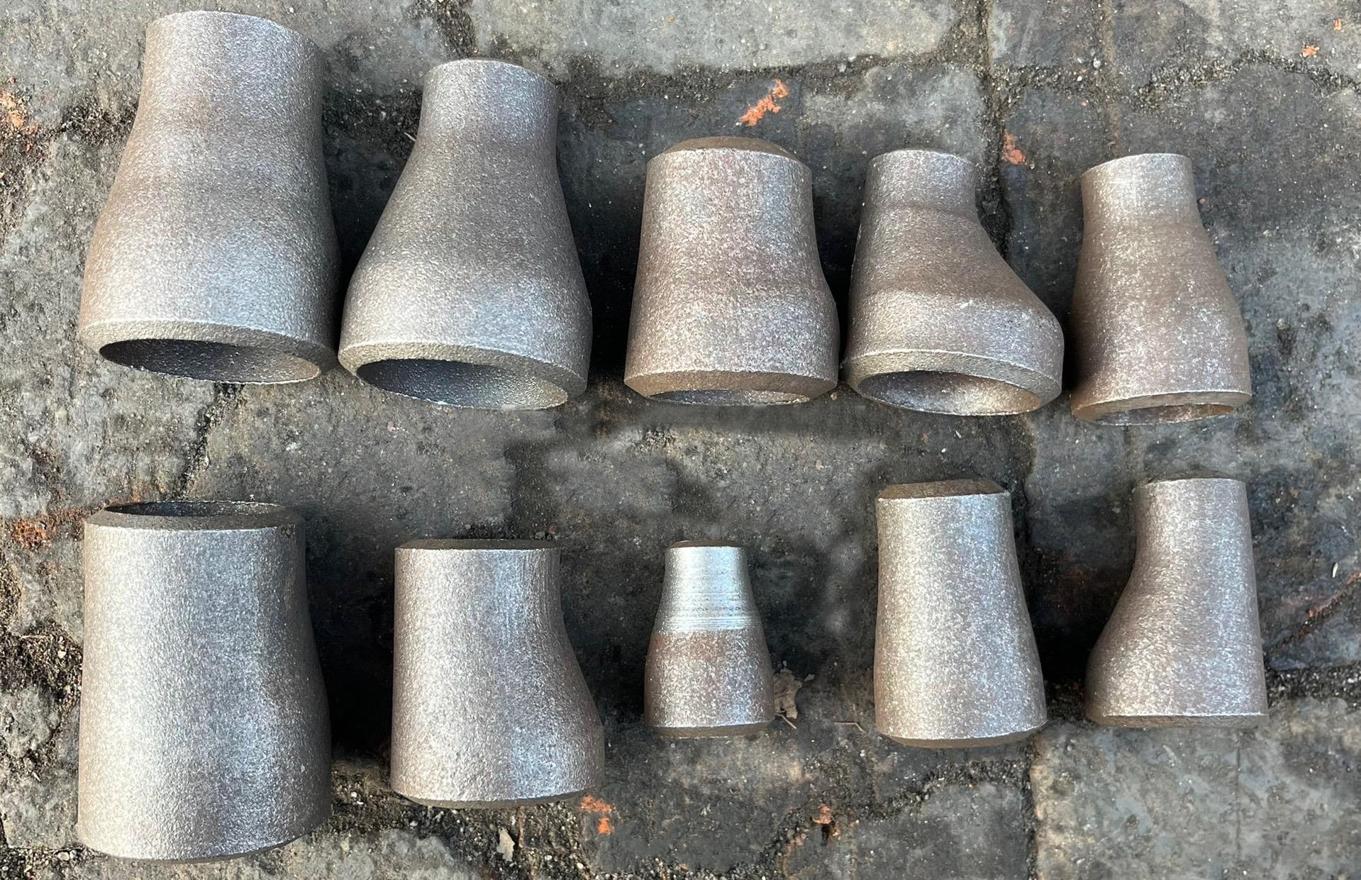
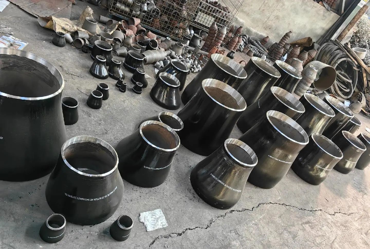
A pipe reducer is a type of pipe fitting used to connect two pipes of different diameters, enabling a smooth transition in pipeline systems. It plays a critical role in maintaining fluid continuity, reducing turbulence, and enhancing overall system stability. Pipe reducers are widely used across various industries, including oil and gas, chemical processing, water supply and drainage, and pharmaceuticals.
Depending on the structural design, pipe reducers are mainly classified into two types:
- Concentric Reducer: A symmetrical, cone-shaped fitting where both the larger and smaller ends share a common centerline.
Typically used in vertical piping systems, such as pump outlets or compressor discharge lines. - Eccentric Reducer: Characterized by one flat side and one sloped side, with offset centerlines between the larger and smaller ends.
Commonly used in horizontal piping systems, especially where fluid or gas accumulation must be avoided, such as pump suction lines or steam pipelines.
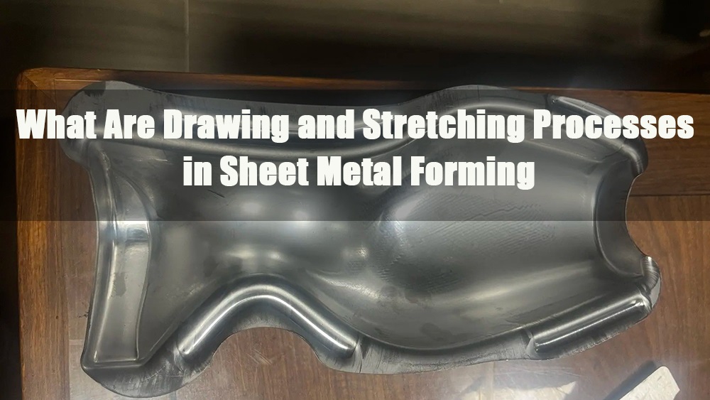
Manufacturing Methods
Pipe reducers are generally produced using hot/cold pressing or forging techniques. The core forming processes include:
- Reducing: The end of a pipe blank is inserted into a forming die, then axially compressed, causing the material to flow along the cavity and reduce the diameter. This may be completed in a single pass or in multiple stages.
- Expanding: Applied when the original pipe diameter is smaller than required. An internal die expands the pipe outward to reach the target size. This method is often used for performing or final sizing of large-diameter reducers.
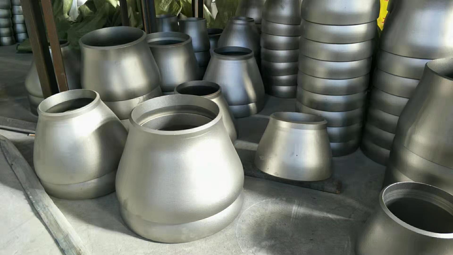
2.0What Is a Concentric Reducer?
A concentric reducer (also referred to as a concentric pipe reducer) is a pipe fitting used to connect two pipes of different diameters, featuring a conical shape with both ends aligned along the same center axis. This symmetrical design allows fluid to transition smoothly from a larger to a smaller diameter, minimizing turbulence and pressure loss. Concentric reducers are commonly used in vertically oriented piping systems.
2.1Structural Features and Working Principle of Concentric Reducers
- Centerline Alignment:
The defining characteristic of a concentric reducer is the shared centerline between its larger and smaller ends. This distinguishes it from an eccentric reducer, in which the centerlines do not coincide. - Conical Shape:
The tapered design allows for a gradual diameter transition, helping maintain consistent fluid velocity and system stability while reducing energy loss and flow disturbance. - Diameter Reduction Function:
Concentric reducers are primarily used to connect pipes of decreasing sizes. They are suitable for single-stage or multi-stage diameter transitions.
2.2Materials and Specifications
Concentric reducers are available in various materials to meet different service conditions and media requirements:
- Metal options: Carbon steel, stainless steel, brass, alloy steel
- Plastic options: PVC, CPVC, and other engineered plastics
Dimensions and pressure ratings are typically customized according to industry standards such as ANSI, DIN, or GB, ensuring compatibility across a wide range of piping systems.
2.3Advantages of Concentric Reducers
- Improved Fluid Performance:
The symmetrical, conical shape ensures stable flow during diameter reduction, minimizing turbulence and pressure drop. - Corrosion Resistance:
Suitable for conveying corrosive fluids (e.g., chemicals, crude oil) or slurries containing solid particles. - Structural Flexibility:
Compatible with various connection types including flanged and welded joints, making installation and system integration straightforward. - Ideal for Vertical Piping Systems:
Particularly effective in vertical pipelines, where it helps prevent fluid accumulation or vapor lock.
3.0What Is an Eccentric Reducer?
An eccentric reducer is a type of welded pipe fitting designed to connect pipes of different diameters. Unlike concentric reducers, the centerlines of the larger and smaller ends are not aligned, resulting in a fitting with one flat side and one sloped side. This offset design makes eccentric reducers especially suitable for horizontal piping systems, where they help prevent the accumulation of gas or condensate, thus reducing the risk of cavitation, vapor lock, or system failure.
3.1Structural Features and Working Principle of Eccentric Reducers
- Offset Design:
Eccentric reducers have one side aligned with the connecting pipe (the “flat side”), creating an offset between the center axes of the two ends. This asymmetry distinguishes them from the symmetrical conical shape of concentric reducers. - Liquid Level Control:
The flat side allows either the top or bottom of the pipe to remain level, enabling directional control of fluid or gas and preventing liquid or gas entrapment in the system. - Hydrodynamic Considerations:
The narrower flow path on one side increases velocity, creating localized pressure differences. Proper configuration is essential based on fluid properties and system requirements. - Bidirectional Use:
The same fitting can be used for reducing (large to small)or expanding (small to large) pipe transitions. The installation orientation should be based on flow direction and engineering guidelines.
3.2Materials and Specifications
Eccentric reducers are available in a range of materials to suit various applications:
- Metals: Carbon steel, stainless steel, alloy steel
(suitable for high-temperature, high-pressure, or corrosive environments) - Plastics: PVC, CPVC, PE
(used in non-metallic systems such as drainage or ventilation)
Common manufacturing standards include ASME B16.9, DIN 2616, and GB/T 12459. Selection is based on pressure classes such as SCH 40/80 to meet system design requirements.
3.3Applications of Eccentric Reducers
- Horizontal Liquid Pipelines:
Flat side facing up to prevent gas accumulation at the top of the pipe, reducing the risk of vapor lock or pump cavitation. - Pipe Rack Installations:
Flat side facing down to maintain a level bottom for uniform load distribution and support. - Horizontal Gas Pipelines:
Flat side down to allow condensate or oil to drain naturally. - Pump Suction Lines:
Eccentric reducers are recommended to prevent air entrapment, which could lead to pump failure.
3.4Advantages of Eccentric Reducers
- Effectively prevent cavitation and vapor lock
- Ensure uniform fluid or gas flow in horizontal pipelines
- Support smooth transfer of specialty media, such as viscous fluids, slurries, or chemicals
- Improve pump system stability and reduce long-term maintenance costs
4.0Concentric vs. Eccentric Reducer: Key Differences in Structure and Application
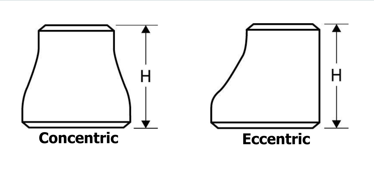
4.1Visual Difference: Fundamental Structural Contrast
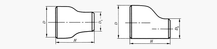
- Concentric Reducer:
Symmetrical conical shape. When viewed from the front, the smaller end is positioned directly at the center of the larger end — both ends share the same centerline. - Eccentric Reducer:
One side remains flat, and the reduction in diameter is offset from the centerline, shifting the smaller end to one side of the larger diameter.
While this variation may seem minor, it plays a critical role in system behavior.
4.2Fluid Dynamics and Application Scenarios
- Concentric Reducers are ideal for vertical piping systems, such as pump discharge lines or vertically oriented fluid or gas flows.
Their symmetrical shape ensures smooth flow transitions, but when used horizontally, they may cause gas or liquid to collect at the top of the pipe — forming air pockets or dead zones. - Eccentric Reducers are particularly advantageous in horizontal pipelines, especially in systems where gas and liquid coexist or where cavitation and trapped air must be avoided.
The flat-side design allows natural venting of gases or drainage of liquids, making them the preferred choice at pump suction lines and similar critical points.
4.3Installation and Cost Considerations
- Concentric Reducers:
Simple to install due to their symmetrical shape; generally more cost-effective. - Eccentric Reducers:
Require careful orientation of the flat side(facing up or down) depending on the system’s design. Slightly higher cost due to their structural complexity and installation demands.
5.0Comparison Table: Concentric vs. Eccentric Reducer
| Feature | Concentric Reducer | Eccentric Reducer |
| Shape & Structure | Symmetrical cone, aligned centerlines | Offset reduction, one side flat |
| Flow Characteristics | Smooth transition, may trap gas/liquid in horizontal setup | Prevents trapped gas or liquid; enables natural drainage |
| Recommended Use | Vertical piping, pump discharge, compressors | Horizontal piping, pump suction, drainage/venting lines |
| Ease of Installation | Easy to install, symmetrical layout | Requires correct orientation, higher installation care |
| Performance in Horizontal Layout | May cause fluid/gas buildup | Effectively prevents accumulation |
| Performance in Vertical Layout | Performs well | Limited use in vertical systems |
| Common Materials | Carbon steel, stainless steel, PVC, CPVC | Same as concentric reducer |
| Cost | Lower | Slightly higher (due to design complexity) |
6.0When to Use a Concentric Reducer
A concentric reducer is suitable for vertical flow applications or systems that require a symmetric, smooth transition between pipes of different diameters. Its conical shape enables diameter reduction without offsetting the centerline, helping maintain fluid stability.
Typical Use Cases:
- Vertical Piping Systems:
Ideal when the flow direction is upward or downward. The aligned centerline reduces turbulence and minimizes backflow risks. - Pump and Compressor Systems:
Used at the inlet or outlet of pumps and compressors to ensure steady pressure and flow before fluid enters or exits the equipment. - Liquid or Gas Transport Lines:
Suitable for process lines or mains requiring balanced flow transition between varying pipe sizes.
7.0When to Use an Eccentric Reducer
An eccentric reducer is recommended for horizontal piping systems, especially where there is a risk of gas entrapment or liquid pooling. The flat-side design ensures that either the top or bottom of the reducer aligns with the pipeline, optimizing drainage and venting.
Recommended Applications:
- Horizontal Piping Systems:
Prevents flow disruption caused by air pockets at high points or liquid accumulation at low points. - Pump Suction Lines:
Installed with the flat side facing up to avoid air entrapment at the pump inlet and reduce the risk of cavitation. - Condensers and Heat Exchangers:
Used to vent gas or drain liquid, ensuring media does not stagnate and improving thermal transfer efficiency. - Systems Carrying Oil, Sludge, or High-Viscosity Fluids:
Helps minimize buildup and reduces pressure loss, supporting smoother flow management.
8.0How to Choose: Concentric vs. Eccentric Reducer
| Selection Criteria | Recommended Type | Rationale |
| Vertical pipe routing | Concentric Reducer | Ensures proper alignment; ideal for gravity-fed systems |
| Horizontal pipe routing | Eccentric Reducer | Prevents air or liquid accumulation; improves drainage and venting |
| Preventing pump cavitation | Eccentric Reducer | Flat side facing up eliminates trapped air before pump inlet |
| Simplified installation | Concentric Reducer | Symmetrical shape is easier to align and weld |
| Handling viscous or abrasive fluids | Eccentric Reducer | Reduces sediment buildup; enhances flow efficiency |
| Emphasis on flow uniformity | Concentric Reducer | Smooth, symmetric transition minimizes turbulence |
Conclusion
- For vertical systems or applications requiring precise alignment, concentric reducers are the preferred choice.
- For horizontal installations, particularly where venting or draining is needed, eccentric reducers are more effective.
- Ensure the flat side is correctly oriented — upward or downward depending on the medium— to optimize performance.
9.0Standard Dimensions of Concentric Reducers (ASME B16.9)
| Large End OD (D1) | Small End OD (D2) | Center Length (L) | Nominal Wall Thickness (SCH 40) |
| 88.9 (DN80) | 60.3 (DN50) | 102 | 5.49 / 3.91 |
| 114.3 (DN100) | 88.9 (DN80) | 127 | 6.02 / 5.49 |
| 141.3 (DN125) | 114.3 (DN100) | 152 | 6.55 / 6.02 |
| 168.3 (DN150) | 114.3 (DN100) | 152 | 7.11 / 6.02 |
| 219.1 (DN200) | 168.3 (DN150) | 178 | 8.18 / 7.11 |
| 273.0 (DN250) | 219.1 (DN200) | 203 | 8.74 / 8.18 |
| 323.9 (DN300) | 273.0 (DN250) | 229 | 10.31 / 8.74 |
| 355.6 (DN350) | 273.0 (DN250) | 229 | 11.13 / 8.74 |
| 406.4 (DN400) | 355.6 (DN350) | 305 | 11.13 / 11.13 |
| 457.0 (DN450) | 406.4 (DN400) | 305 | 12.70 / 11.13 |
Notes:
- D1 / D2: Outside diameters of the large and small ends, in millimeters, corresponding to nominal pipe sizes (DN).
- L: Overall length along the centerline of the reducer. ASME B16.9 allows a manufacturing tolerance of ±12 mm.
- Wall Thickness: Based on pressure rating, such as SCH 20, SCH 40, or SCH 80. Values shown here are for Schedule 40(first value for D1, second for D2).
10.0Typical Dimensions of Eccentric Reducers (ASME B16.9)
| Large End OD (D1) | Small End OD (D2) | Minimum Center Length (L) | Nominal Wall Thickness (SCH 40) |
| 88.9 (DN80) | 60.3 (DN50) | 102 | 5.49 / 3.91 |
| 114.3 | 88.9 | 127 | 6.02 / 5.49 |
| 141.3 | 114.3 | 152 | 6.55 / 6.02 |
| 168.3 | 114.3 | 152 | 7.11 / 6.02 |
| 219.1 | 168.3 | 178 | 8.18 / 7.11 |
| 273.0 | 219.1 | 203 | 8.74 / 8.18 |
| 323.9 | 273.0 | 229 | 10.31 / 8.74 |
| 355.6 | 273.0 | 229 | 11.13 / 8.74 |
| 406.4 | 355.6 | 305 | 11.13 / 11.13 |
| 457.0 | 406.4 | 305 | 12.70 / 11.13 |
| 508.0 | 457.0 | 305 | 12.70 / 12.70 |
Notes:
- D1 / D2: Outside diameters of the large and small ends, compliant with ASME B36.10M.
- L: Minimum centerline length as specified in ASME B16.9. Actual manufactured lengths may exceed the minimum.
- Wall Thickness: Depends on system design and is typically selected according to standard pipe schedules (e.g., SCH 40, SCH 80). The values listed are representative of Schedule 40(first value for D1, second for D2).
11.0Manufacturing Processes & Equipment for Pipe Reducers
Metal reducers—especially butt-welded carbon steel and stainless steel reducers—are typically produced via hot pressing, cold pressing, or combined expanding and reducing techniques, depending on material type, size, and batch volume. Below are the major forming methods and associated equipment:
11.1Hydraulic Press Forming
Suitable for: Small to medium diameters (DN50–DN400), performed either hot or cold.
Key Equipment:
- Hydraulic Press: Commonly rated at 300T, 500T, or 800T.
- Reducer Die Set: Custom-designed concentric or eccentric cavity molds.
- Induction Heater / Furnace: Used for preheating blanks in hot-forming processes.
Process Steps:
- Cut the base pipe section to match the large end size.
- Heat the blank to forming temperature (typically above 800°C for hot forming).
- Press the blank into the mold using a hydraulic ram.
- Metal flows along the die cavity to form the reducer.
- Deburr, reshape, and heat treat as required.
11.2Mechanical Expanding & Reducing
Ideal for: Large-diameter or thick-wall reducers (DN450 and above), especially where single-step forming is impractical.
Key Equipment:
- Tube Expander: Enlarges the small end to the required large diameter.
- Tube End Reducer: Compresses one end to achieve a smaller diameter.
- Hydraulic Servo Control System: Controls dimensional accuracy.
- Forming Rollers: Matched to the reducer’s internal diameter and wall thickness.
- Medium-Frequency Heater: Assists in thermal plastic deformation.
Process Notes:
Suitable for reducers with significant diameter and wall thickness differences.
May involve “expand first, then reduce” or multi-step reductions for greater precision.
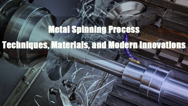
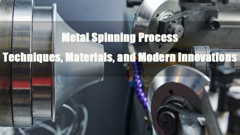
11.3Spinning Forming
Suitable for: Symmetrical reducers with conical or tapered profiles, typically in the DN100–DN500 range, especially when wall thickness varies significantly.
Key Equipment:
- CNC Spinning Machine: Controls roller pressure and path with high precision.
- Rotary Chuck or Mandrel: Holds and rotates the workpiece during forming.
- Preform Blank: Usually a pre-shaped disc or short pipe section.
- Heating System (Optional): Induction or flame heater for warm or hot spinning.
Process Steps:
- Mount the preform blank onto the mandrel.
- Rotate the workpiece at high speed.
- Apply forming rollers gradually to shape the material over the mandrel, reducingthe diameter while maintaining wall integrity.
- Trim or machine the reducer as needed.
- Perform heat treatment if required to relieve stresses.
Process Notes:
- Ideal for producing concentric reducers with smooth transitions and uniform wall distribution.
- Offers high-dimensional accuracy and surface finish with minimal material waste.
Suitable for small to medium production volumes due to flexible tooling.
11.4Plate Rolling Forming
Used when: Manufacturing large-diameter reducers (typically DN600 and above) where seamless forming is not feasible. Often used for custom-size eccentric or concentric reducers made from plate material.
Key Equipment:
- Plate Rolling Machine (3-roll or 4-roll): Rolls metal plate into conical or cylindrical shapes.
- Edge Beveling Machine: Prepares edges for welding.
- Welding Equipment (GMAW/SMAW/SAW): Joins the plate edges longitudinally.
- Heat Treatment Furnace: For post-weld stress relief.
- Machining Tools: For dimensional finishing and end-face preparation.
Process Steps:
- Cut metal plate to required dimensions based on reducer size.
- Bevel the edges to prepare for welding.
- Roll the plate into the desired cone or cylinder shape using a plate rolling machine.
- Weld the longitudinal seam (internal and external) with the appropriate technique.
- Perform non-destructive testing (UT/RT) to verify weld quality.
Heat treat and machine the final shape as needed.
11.5Die Forging
Used for: High-strength reducers with thick walls, often in petrochemical or pressure vessel applications.
Key Equipment:
- Forging Press: Typically 1000T to 1600T hydraulic forging machines.
- Forging Dies: Designed with eccentric or concentric tapered cavities.
- Power Hammer or Electro-Hydraulic Hammer: Used in open-die setups.
- Annealing Furnace: For heat treatment after forging.
11.6Welded Construction (Optional Method)
Used when: Reducer dimensions or wall thickness make seamless forming impractical. Fabrication involves welding two pipe sections together and machining to final dimensions.
Key Equipment:
- Beveling Machine: Prepares ends for welding.
- Circumferential Welding Machine: Performs precision welding around pipe perimeter.
- X-ray Testing Equipment (RT): Inspects weld quality.
- NDT Equipment (UT/MT): Ensures weld integrity via ultrasonic or magnetic testing.
11.7Equipment Summary Table
| Process Type | Key Equipment | Application Description |
| Hydraulic Forming | Hydraulic press, die set, heater | One-step cold/hot forming for small-medium sizes |
| Expanding & Reducing | Expander, reducer, rollers, heater system | Controlled dual-end forming |
| Die Forging | Forging press, dies, power hammer | High-strength forming for thick-walled reducers |
| Welded Construction | Welding machine, beveler, NDT tools | Used for oversized reducers or fabrication cases |
12.0Pipe Reducer Standards and Dimensional Specifications
Reducers must comply with widely recognized industry standards to ensure interchangeability and compatibility. Common standards include:
- ASME B16.9– Butt-welding Fittings
- DIN EN 10253– Steel fittings for industrial pipelines (Europe)
- GB/T 12459– National Standard of China for forged steel fittings
- Other applicable codes:I SO, JIS, etc.
These standards define critical parameters such as diameter range, tolerances, wall thickness, pressure class, and material grades.
13.0Pipe Reducer Installation Methods and Key Considerations
Pipe reducers can be installed using various techniques based on system pressure, pipe material, and connection requirements:
- Butt Welding: Preferred in high-pressure systems due to its strength and reliability.
- Socket Welding: Common for smaller diameter metallic pipes.
- Threaded Connection: Suitable for small, detachable pipelines.
- Flanged Connection: Used for equipment joints or easily replaceable lines.
Important Installation Notes:
- Eccentric Reducers: Must be installed with the flat side aligned downward in horizontal lines to prevent fluid accumulation.
- Welded Joints: Should be subjected to non-destructive testing (NDT) to detect leaks or defects.
- Flow Direction: Always follow flow markings during installation to avoid increased resistance or flow instability.
14.0Applications of Pipe Reducers
Pipe reducers are widely used across various industrial and commercial sectors to manage transitions between different pipe diameters. Common applications include:
- Oil & Gas:
Connecting transmission lines for oil and gas, adapting interfaces for drilling and production equipment. - Chemical & Pharmaceutical:
Controlling flow between vessels such as reactors, condensers, or process tanks. - Food & Beverage Processing:
Ensuring hygienic fluid transfer and compatibility between different equipment sizes. - HVAC Systems:
Diameter transitions in chilled water, hot water, or air distribution ductwork. - Water Supply & Drainage:
Used as transitional fittings in potable water, wastewater, and stormwater systems.
15.0Common Materials Used for Pipe Reducers
Depending on service conditions and the nature of the conveyed media, pipe reducers are available in a variety of materials:
- Stainless Steel:
Excellent corrosion resistance; widely used in food processing, pharmaceuticals, and chemical systems. - Carbon Steel:
High strength and cost-effective; suitable for general industrial and utility pipelines. - Copper:
Good thermal conductivity; ideal for HVAC and hot/cold water systems. - PVC / CPVC (Plastic):
Suitable for low-pressure and corrosion-resistant applications, especially in non-metallic systems. - Alloy Steel:
Used in high-pressure, high-temperature, or chemically aggressive environments.
16.0Conclusion
Pipe reducers are essential components in modern piping systems.
They play a critical role in managing flow transitions, maintaining operational stability, and adapting to various system configurations.
By selecting the appropriate type, material, and manufacturing method, users can enhance safety, improve system efficiency, and reduce both installation costs and maintenance frequency.
17.0Common FAQs about Pipe Reducers
What is a Pipe Reducer?
A pipe reducer is a fitting used to connect two pipes of different diameters, enabling smooth fluid flow transition. It is commonly used in industries such as oil & gas, chemical, pharmaceutical, and water supply systems.
What types of Pipe Reducers are there?
- Concentric Reducer: Has aligned centerlines at both ends, forming a symmetrical cone shape. Suitable for vertical piping systems.
- Eccentric Reducer: Centerlines at each end are offset, with one flat side. Designed for horizontal piping to prevent gas or liquid accumulation.
What is the difference between Concentric and Eccentric Reducers?
- Structure: Concentric reducers are symmetrical cones; eccentric reducers have a flat side on one end.
- Applications: Concentric is used in vertical pipelines; eccentric is used in horizontal pipelines, especially to avoid cavitation and liquid trapping.
- Installation: Eccentric reducers require attention to flat side orientation (facing up or down); concentric reducers are simpler to install.
When should I choose a Concentric Reducer?
Choose concentric reducers when the pipeline is vertically oriented or when fluid flow needs to remain centered and uniform.
When should I choose an Eccentric Reducer?
Choose eccentric reducers for horizontal pipelines where prevention of gas buildup or liquid pooling is critical, especially at pump suction inlets.
References
https://en.wikipedia.org/wiki/Concentric_reducer
https://en.wikipedia.org/wiki/Eccentric_reducer
steelforgings.com/2020/09/17/concentric-vs-eccentric-pipe-reducer/