
- 1.0What Is a Machining Process System?
- 2.0How Are Machined Surfaces of Mechanical Parts Formed?
- 3.0What Are Generating Lines on a Workpiece Surface? What Methods Are Used to Form Them?
- 4.0What Motions Are Required in Workpiece Machining?
- 5.0What Is Cutting Motion? How Is It Classified?
- 6.0What Is Compound Cutting Motion?
- 7.0What Are Auxiliary Motions?
- 8.0Frequently Asked Questions
In the field of mechanical manufacturing, the machining process system is the core framework that enables precise part production. The following sections break down its underlying principles and operating logic through a series of structured explanations.
1.0What Is a Machining Process System?
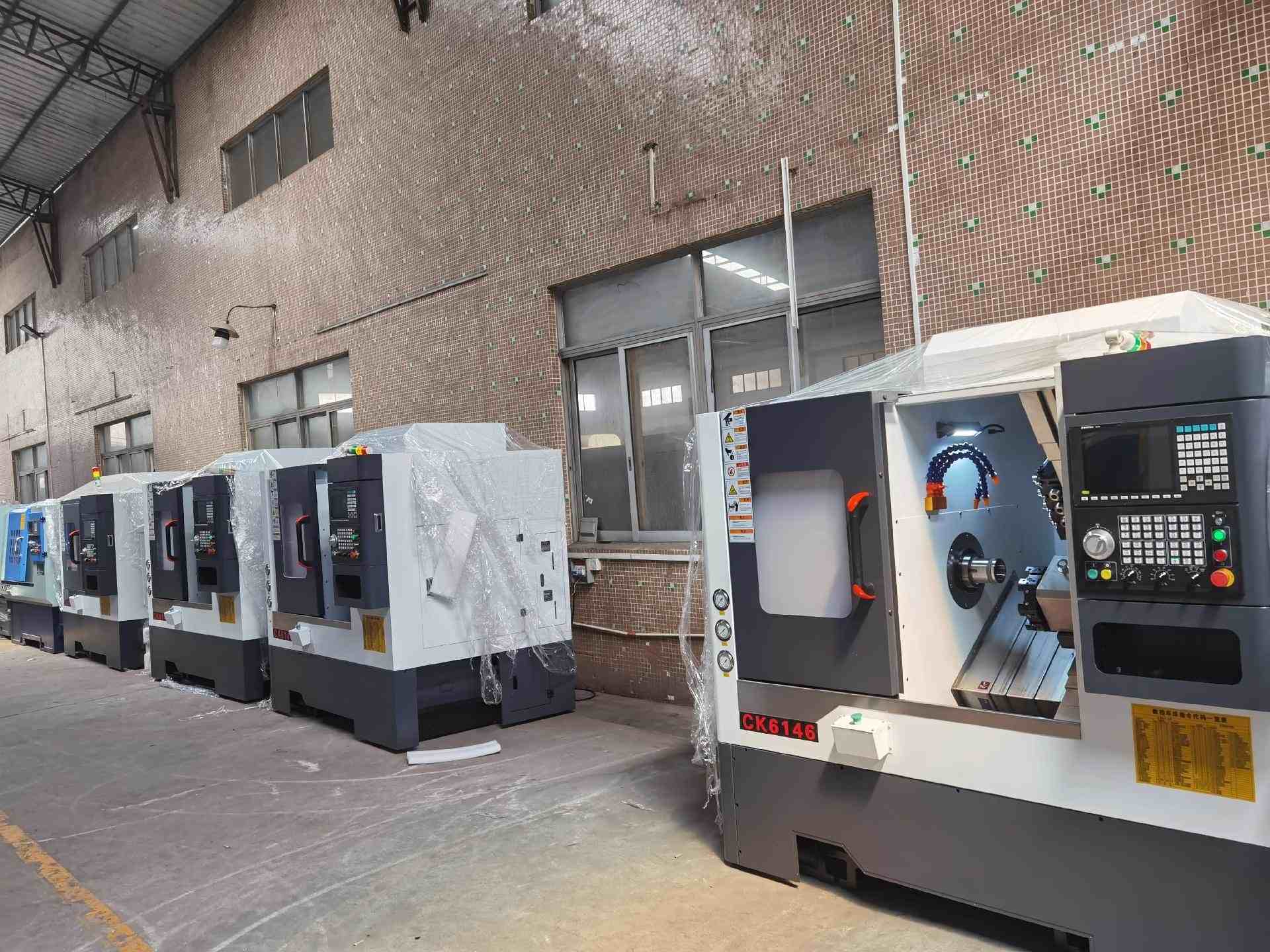
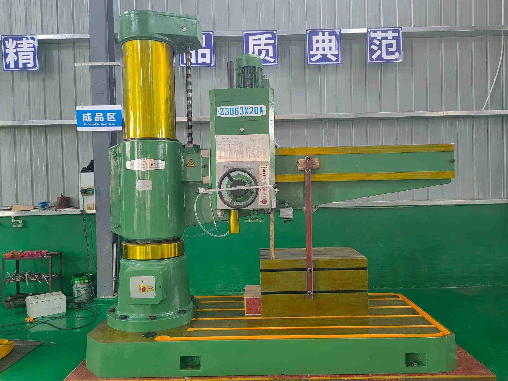
A machining process system, commonly referred to as a process system, is a cutting system composed of various machine tools such as lathes, milling machines, and grinding machines, combined with cutting tools, fixtures, and the workpiece. Its primary function is to transform raw materials or blanks into mechanical parts with specified shapes, dimensions, and quality requirements. Whether a process system can meet machining demands and achieve the required surface formation depends not only on appropriate geometric and process parameters, but also on the inherent characteristics of each component and the overall system behavior formed through their interaction.
2.0How Are Machined Surfaces of Mechanical Parts Formed?
Regardless of how complex a mechanical part may appear, its surfaces are ultimately composed of combinations of basic surface types. The essence of machining is the process of generating the required functional surfaces through specific cutting methods.
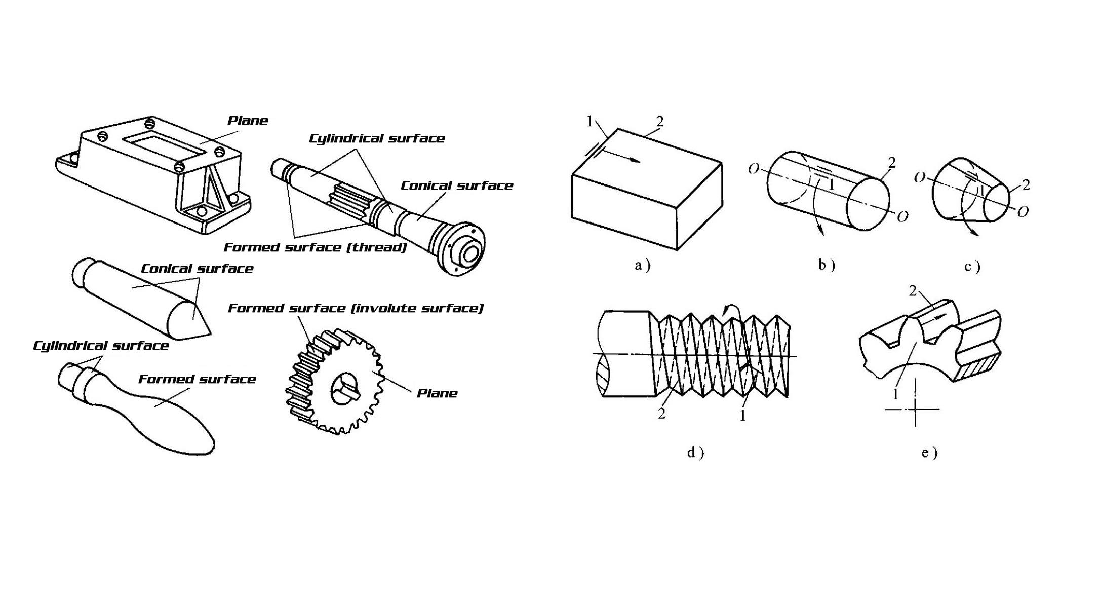
2.1Common Types of Workpiece Surfaces
- Planes
- Cylindrical surfaces
- Conical surfaces
- Formed surfaces (such as thread surfaces and involute gear tooth surfaces)
- Special surfaces (such as spherical surfaces, toroidal surfaces, and hyperbolic surfaces)
2.2How Are Workpiece Surfaces Generated?
Most standard mechanical surfaces can be formed by the movement of one generatrix along another directrix. The generatrix and directrix, collectively referred to as generating lines, are the fundamental elements that define a surface.During machining on conventional lathes, CNC milling machines, and similar equipment, the relative and coordinated motions of the workpiece and the cutting tool generate these two lines, thereby producing the desired surface geometry.
3.0What Are Generating Lines on a Workpiece Surface? What Methods Are Used to Form Them?
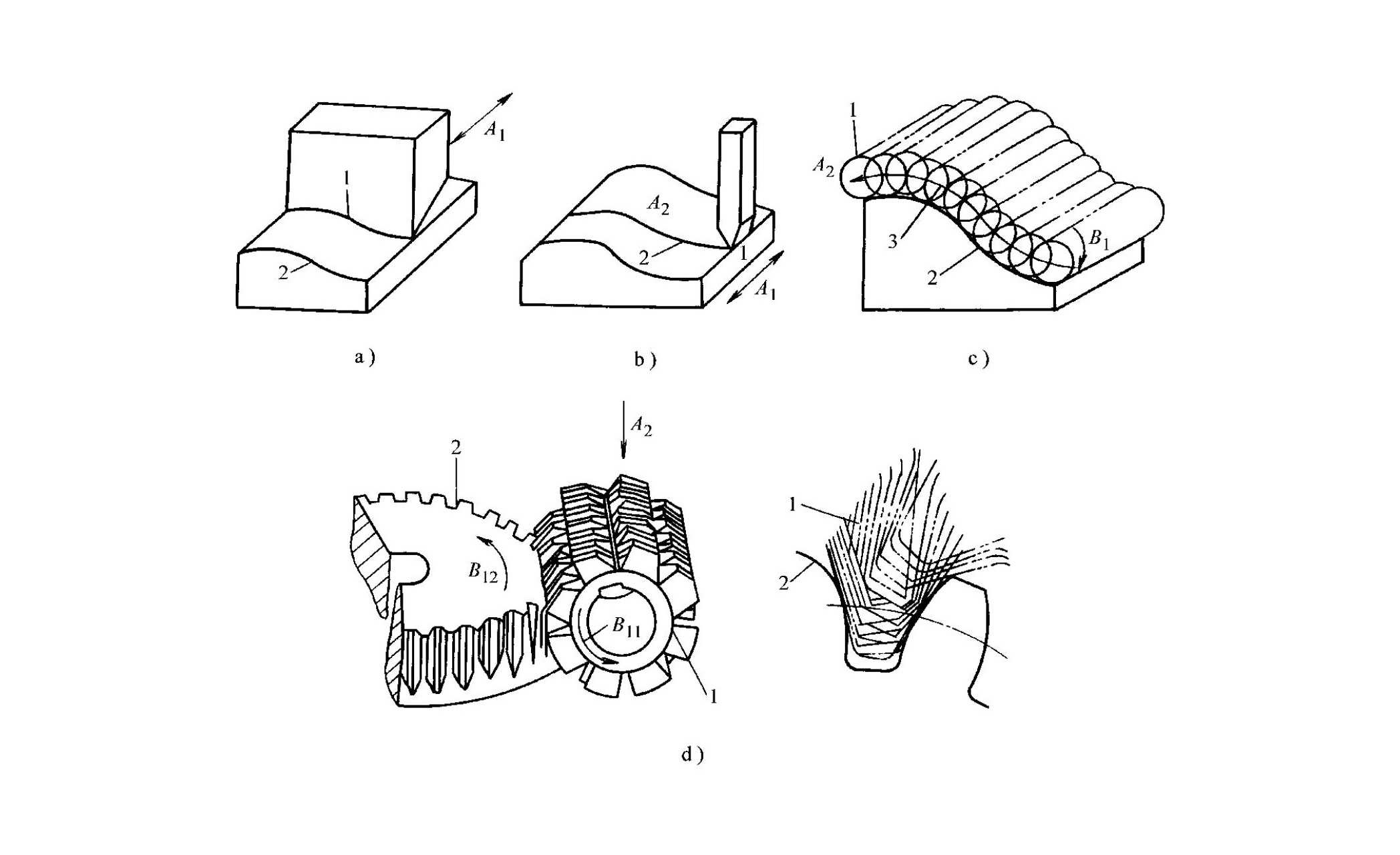
Generating lines refer collectively to the generatrix and the directrix that constitute a workpiece surface. To create a machined surface, these two generating lines must first be produced through specific methods. At present, the formation of generating lines can be broadly classified into four main approaches.
Forming Method: Cutting Edge Directly Replicates the Generatrix. The forming method is characterized by line contact, the cutting edge of the tool is in line contact with the workpiece surface, and the shape of the cutting edge exactly matches one generating line of the surface. Example: When planning a curved surface on a shaper, the profile of the tool’s cutting edge corresponds to the generatrix of the workpiece surface, and the generatrix is formed directly by the tool geometry.
Trajectory Method: Tool Tip Motion Generates the Generating Line. The trajectory method involves approximate point contact, where the generating line is produced by the motion path of the tool tip.Examples:
- Planning a flat surface on a gantry planer: the straight-line motion of the tool forms a straight generatrix
- Machining a curved surface on a CNC milling machine: the tool’s movement along a curved path forms a curved directrix
Tangential Method: Envelope of Rotating Tool Paths Forms the Line. In the tangential method, rotating tools such as milling cutters or grinding wheels are used. The tool rotates while simultaneously moving along a defined path, and the motion trajectories of the cutting edges envelope the generating line of the surface. Examples:
- Surface milling on a vertical milling machine: the combination of cutter rotation and center-path movement causes the cutting point trajectories to envelope the required generating line
- Grinding a cylindrical surface on an external cylindrical grinder: the rotation of the grinding wheel combined with axial feed generates the generating line through tangential action
Generating Method: Rolling Motion Produces an Involute The generating method relies on generating cutting motion between the tool and the workpiece. The cutting edge and the formed surface are in point contact, and the tool rolls relative to the workpiece in a generating motion. The envelope of the cutting-edge positions over time constitutes the generating line. Examples:
- Cylindrical gear hobbing on a hobbing machine: the hob and the workpiece rotate synchronously in a generating motion, and the envelope of the hob cutting edges forms the involute generatrix of the gear tooth surface
- Gear shaping on a gear shaper also belongs to the generating method
4.0What Motions Are Required in Workpiece Machining?
To obtain a workpiece surface that meets design requirements, specific motions must be applied to the tool and the workpiece so that generating lines are formed using the methods described above.These motions can be divided into surface-forming motions and cutting motions. Surface-forming motions are defined from a geometric perspective, while cutting motions are defined from the practical standpoint of metal cutting.
4.1What Is Surface-Forming Motion?
Surface-forming motion refers to the motion required to generate the generating lines of a workpiece surface. Its type and number depend on the shape of the surface being machined, the machining method, and the tool structure.
| Motion Type | Definition | Example |
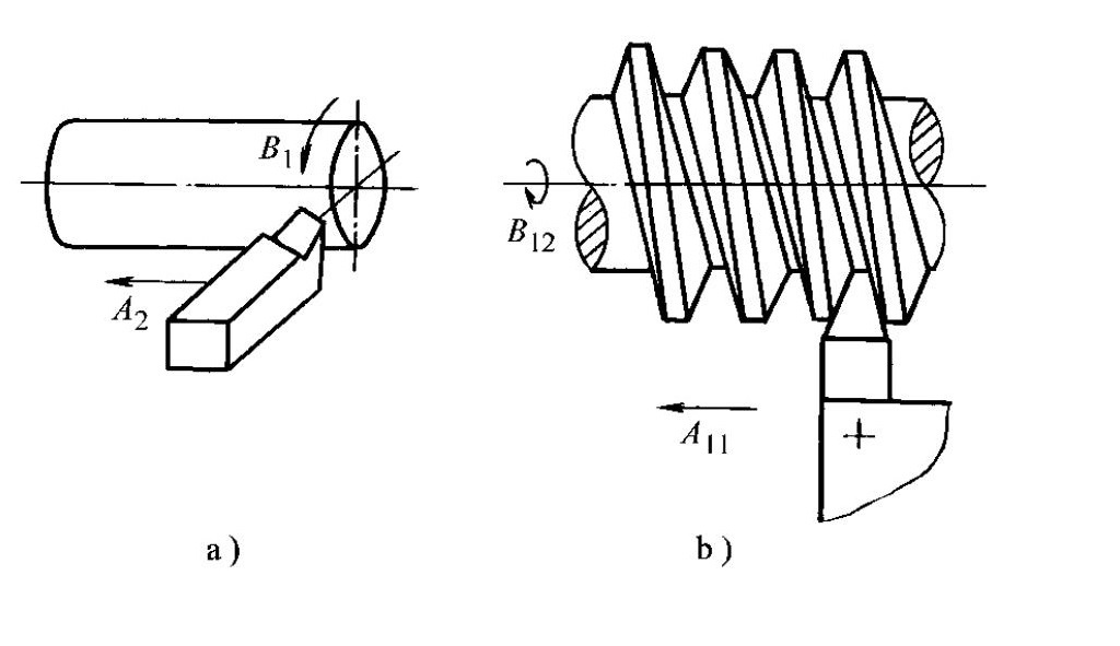
| Simple Motion | A forming motion achieved by a single rotational or linear movement | Turning an external cylinder on a conventional lathe: the rotation of the workpiece and the longitudinal linear feed of the tool |
| Compound Motion | A motion composed of two or more rotational and linear motions combined under a strictly defined relative relationship | 1. Thread turning on a lathe: the combination of workpiece rotation and tool linear feed2. Gear hobbing: the generating motion between the hob and the workpiece |
5.0What Is Cutting Motion? How Is It Classified?
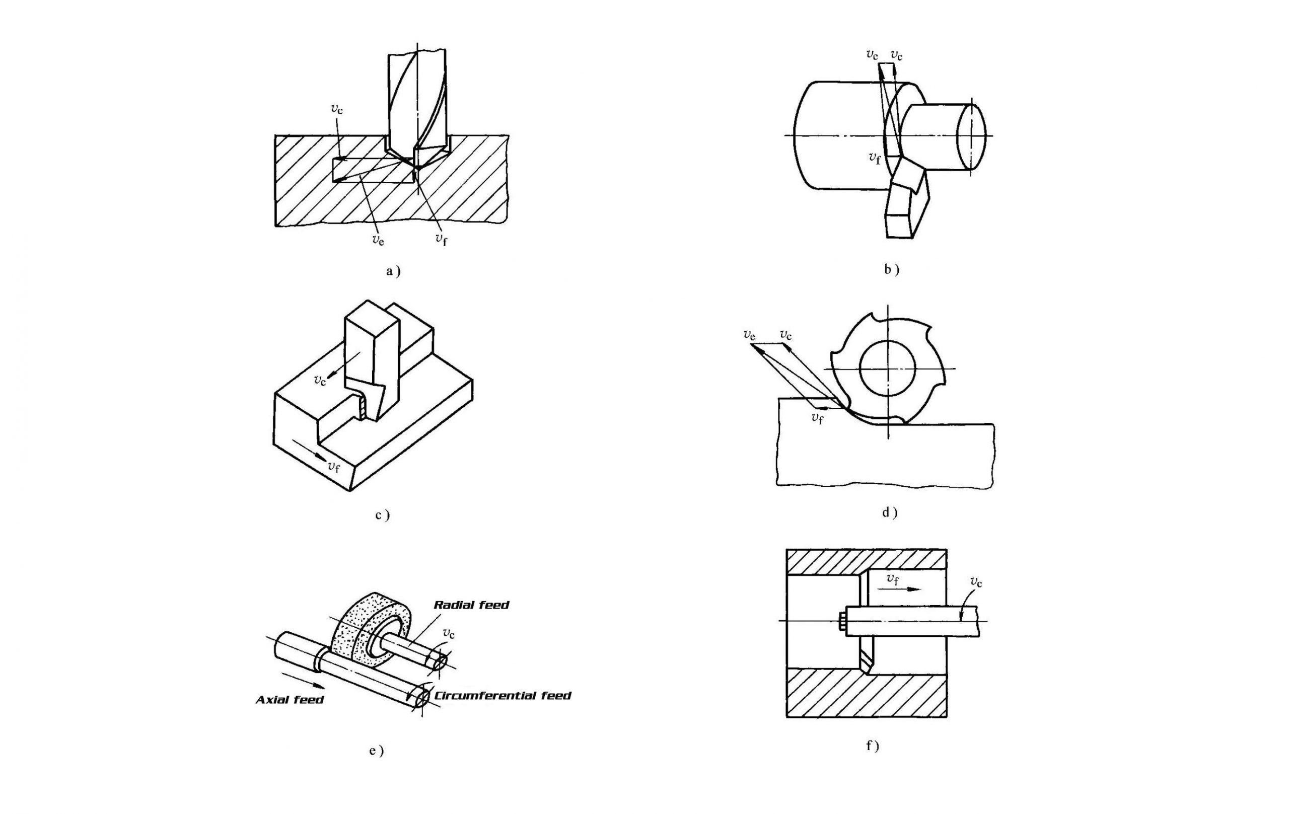
In metal cutting, the relative motion between the tool and the workpiece that removes excess material is referred to as cutting motion. In practical machining, surface-forming motions are manifested as cutting motions. Depending on their function, cutting motions are classified into primary motion and feed motion.
| Motion Type | Core Characteristics | Examples |
| Primary Motion: The Core Motion for Material Removal | – Main motion provided by the machine tool- Purpose: create relative movement to remove the cutting layer- Features: highest cutting speed, greatest power consumption, only one primary motion per operation | – Rotational motion: workpiece rotation during turning on a conventional lathe; cutter rotation during milling on a vertical milling machine- Linear motion: reciprocating linear motion of the tool during planing on a shaper |
| Feed Motion: The Auxiliary Motion for Continuous Cutting | – Additional motion supplied by the machine tool- Purpose: cooperate with primary motion to achieve continuous or intermittent cutting- Features: lower power consumption, number can be one, multiple or none | – Continuous motion: longitudinal movement of a turning tool during external turning on a conventional lathe- Intermittent motion: transverse movement of the workpiece during planing on a shaper- Multiple motions: transverse feed of the grinding wheel in external cylindrical grinding- No motion: broaching |
6.0What Is Compound Cutting Motion?
When the primary motion and the feed motion occur simultaneously, their resultant is referred to as compound cutting motion.
- The instantaneous direction of motion of a selected point on the cutting edge relative to the workpiece is called the compound cutting direction.
- The velocity of this point, defined as the vector sum of the primary motion velocity and the feed motion velocity, is known as the compound cutting speed (expressed as: ve = vc + vf).
Examples of compound cutting motion:
- External turning on a conventional lathe: the combination of workpiece rotation (primary motion, vc) and the longitudinal feed of the tool (feed motion, vf) produces a helical trajectory for the selected point on the cutting edge
- External cylindrical grinding: the rotation of the grinding wheel and the axial movement of the workpiece act together
7.0What Are Auxiliary Motions?
In addition to cutting motions, machine tools require auxiliary motions to adjust the relative positions of the tool and the workpiece or to perform supporting operations. These motions do not directly participate in material removal, but they are essential for ensuring smooth and efficient machining operations.
Common examples of auxiliary motions:
- Rapid tool approach and retraction on CNC lathes
- Spindle retraction on radial drilling machines
- Indexing motion of a dividing head used in conjunction with a milling machine
8.0Frequently Asked Questions
Q1: What are the core components of a machining process system?
A: A machining process system consists of four main elements, machine tools such as lathes, milling machines, and grinding machines, together with cutting tools, fixtures, and the workpiece. These components work as an integrated system to complete the cutting process from raw stock to qualified finished parts.
Q2: What is the main difference between primary motion and feed motion?
A: Primary motion is the fundamental motion responsible for metal removal. It features the highest cutting speed, the greatest power consumption, and exists as a single motion in any cutting operation. Feed motion is an auxiliary motion that works in coordination with the primary motion to achieve continuous or intermittent cutting. It consumes much less power and may consist of one, multiple, or even no feed motions, depending on the machining process.
Q3: Why is compound cutting speed defined as the vector sum of the primary and feed motion speeds?
A: Primary motion and feed motion occur simultaneously as relative motions between the tool and the workpiece. Since velocity is a vector quantity, both magnitude and direction must be considered. Therefore, compound cutting speed is expressed as the vector sum of the primary motion speed and the feed motion speed.
Q4: What is the most typical application of the generating method?
A: The most typical application is the machining of cylindrical gears on a hobbing machine. Through generating motion, synchronous rotation, between the hob and the workpiece, the envelope of the hob cutting edges forms the involute generatrix of the gear tooth surface. Gear machining on a gear shaper also belongs to the generating method.
Q5: If auxiliary motions do not participate in material removal, why are they still important?
A: Auxiliary motions are responsible for adjusting the relative positions of the tool and the workpiece and for completing operations such as clamping, positioning, and indexing. They provide essential support to ensure continuous, efficient machining. Without auxiliary motions, a machine tool cannot complete a normal machining cycle.
Reference
https://bharatforge.eu/artikel/what-is-machining-procedure-significance-and-applications/?lang=en
https://admati.com/the-importance-of-machining-types-of-equipment-and-machining-methods/
https://www.nutech.de/en/services/machining/