
Metal cutting is one of the most fundamental and critical manufacturing methods in mechanical engineering. Whether it is turning on a lathe, milling on a milling machine, boring on a boring machine, or precision material removal on modern CNC systems such as Tube Laser Cutting Machines, the core principle remains the same: removing excess material from a workpiece to achieve the required shape, dimensions, and surface quality.
To gain a solid understanding of the metal cutting process, it is essential to analyze it from three key aspects: cutting elements, cutting parameters, and cutting layer geometry.
1.0What Are Cutting Elements in Metal Cutting
Metal cutting refers to a machining process in which a cutting tool applies cutting motion to a workpiece on a machine tool, causing excess material to be removed in the form of chips. Typical machine tools include lathes, milling machines, drilling machines, and boring machines.
The basic elements of metal cutting mainly include:
- Cutting motion: including the main motion and the feed motion (for example, workpiece rotation is the main motion on a lathe, while tool rotation is the main motion on a milling or drilling machine)
- Cutting parameters
- Cutting layer and its geometric parameters
These elements collectively determine cutting efficiency, machining accuracy, and tool life.
Summary: Cutting elements form the theoretical foundation for analyzing the cutting process, selecting cutting parameters, and optimizing machining strategies across different types of machine tools.
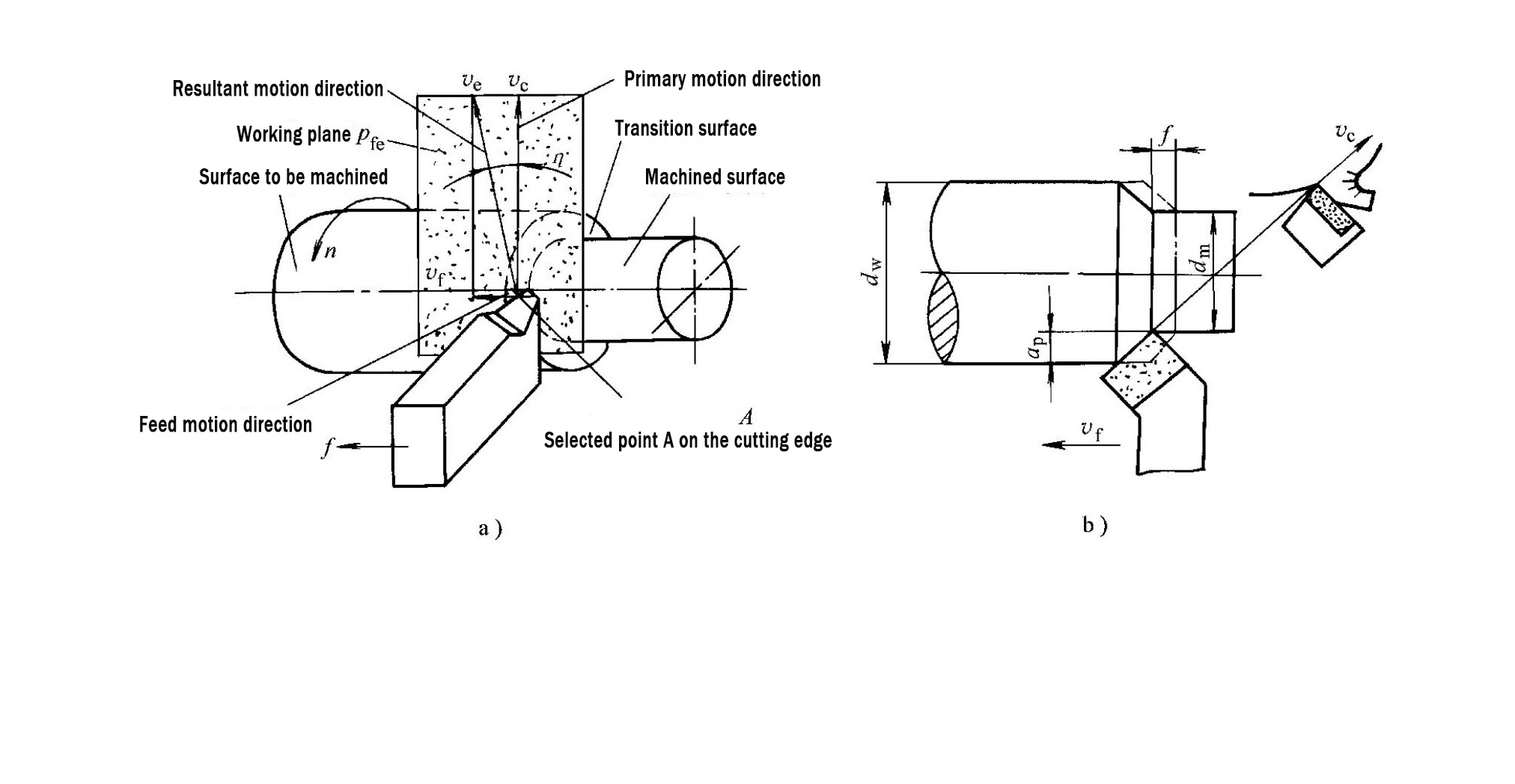
2.0Classification of Workpiece Surfaces in Cutting Operations
During the cutting process, the workpiece surface is not static but continuously evolves as material is removed. This phenomenon is common to all metal cutting operations, and the surfaces are generally classified into three categories:
- Machined surface: the surface that has already been cut by the tool, forming the final or intermediate dimensions of the workpiece
- Surface to be machined: the surface that has not yet been cut and will be removed by the next cutting layer
- Transition surface: the surface currently being formed by the cutting edge, which will be further removed in the next cutting pass or revolution
Summary: The cutting layer exists between the surface to be machined and the machined surface, while the transition surface acts as a dynamic interface connecting the two.
3.0What Are Feed and Feed Rate
3.1Feed
Feed refers to the displacement of the tool relative to the workpiece in the feed direction and reflects the material removal “density” during cutting. Its definition varies slightly depending on the machine type:
- Feed per revolution:
$$
f \text{ (mm/r)}
$$
Mainly used for lathes and boring machines.
- Feed per tooth:
$$
f_z \text{ (mm/tooth)}
$$
Commonly used for multi-tooth tools on milling machines, drilling machines, and reamers.
For example, in external turning on a lathe, the feed
$$
f
$$
represents the axial distance the tool advances during one full revolution of the workpiece.
3.2Feed Rate
Feed rate is the instantaneous velocity of the selected point on the cutting edge relative to the workpiece in the feed direction and is expressed in mm/min.
$$
v_f = f \cdot n = z \cdot n \cdot f_z
$$
Where:
– \(v_f\) is the feed rate
– \(f\) is the feed per revolution
– \(f_z\) is the feed per tooth
– \(n\) is the spindle speed (r/min)
– \(z\) is the number of cutting teeth
Engineering interpretation: When other conditions remain unchanged, increasing the feed increases cutting layer thickness, leading to higher cutting forces and greater tool load.
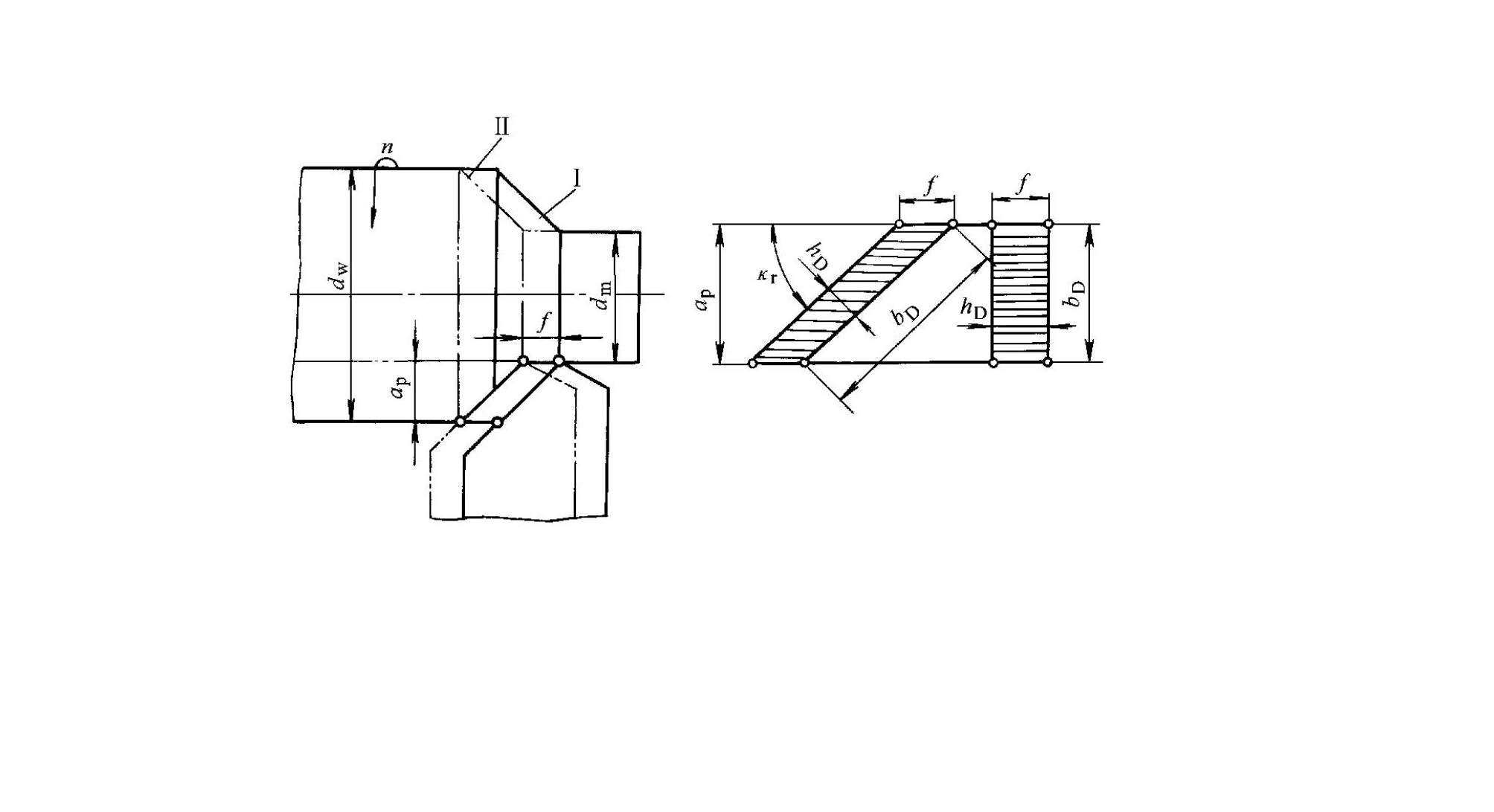
4.0What Is Depth of Cut
Depth of cut refers to the cutting depth measured through the selected point on the cutting edge, perpendicular to the working plane. The unit is mm, and its definition depends on the machining method.
4.1Common calculation methods
- External turning on a lathe:
$$
a_p = \frac{d_w – d_m}{2}
$$
- Boring operations:
The same formula applies, with (d_w) and (d_m) interchanged. - Milling:
Depth of cut is typically defined as the vertical engagement depth of the tool relative to the workpiece. - Sheet shearing:
Depth of cut corresponds to the thickness of the sheet material cut in a single pass.
Where:
– \(a_p\) is the depth of cut
– \(d_w\) is the diameter of the surface to be machined
– \(d_m\) is the diameter of the machined surface
Engineering interpretation: In rough machining, increasing
$$
a_p
$$ is usually prioritized to improve metal removal rate. In finishing operations, a smaller depth of cut is preferred to achieve better surface quality.
5.0Conclusion: Why Understanding the Cutting Layer Matters
Cutting parameters determine cutting layer geometry, and cutting layer parameters directly influence the overall machining performance of metalworking equipment.
Key effects include cutting force magnitude, cutting temperature, tool wear and tool life, and machined surface quality.
A rational selection of cutting parameters must be based on a clear understanding of the fundamental characteristics of the cutting layer.
6.0FAQ: Frequently Asked Questions About Metal Cutting
Q1: Which cutting parameter has the greatest impact on tool life?
A: Cutting speed has the most significant influence on tool life because it directly affects cutting temperature and wear mechanisms.
$$
v_c = \frac{\pi d n}{1000}
$$
Q2: Can increasing feed always improve machining efficiency?
A: No. Although higher feed increases material removal rate, it also increases cutting force and tool load, which may reduce tool life or surface quality.
Q3: How do cutting layer parameters affect surface finish?
A: Larger cutting layer thickness generally increases cutting force and vibration, which can degrade surface finish. Optimizing
$$
f \text{ and } a_p
$$
helps balance efficiency and surface quality.