- 1.0What is Plasma Cutting
- 2.0Plasma Cutting Process Types Explained
- 3.0Plasma Cutting Common Applications and Specific Product Applications
- 4.0Plasma Cutting FAQ
- 4.1How does plasma cutting compare to oxy-fuel cutting?
- 4.2What is dross, and how can it be minimized?
- 4.3What is the difference between drag cutting and stand-off cutting?
- 4.4What is the ideal cutting distance between the torch and the workpiece?
- 4.5What is kerf width, and how does it affect my cut?
- 4.6What is beveling, and when should it be used?
This article will provide a detailed explanation of plasma cutting process types, operational techniques, and common applications, helping users better understand and apply this technology to enhance cutting quality and production efficiency.
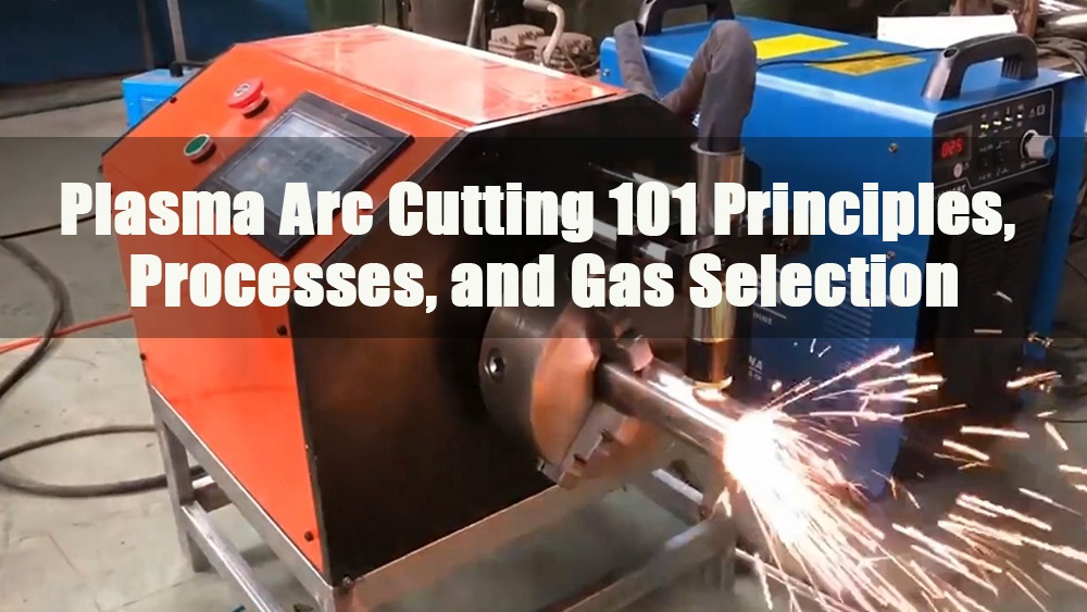
1.0What is Plasma Cutting
Plasma cutting works by creating an arc between the electrode and the workpiece, which is constricted by a fine bore nozzle. This increases the temperature (over 20,000°C) and velocity of the plasma, which can approach the speed of sound. The high-temperature plasma jet melts the metal, while the arc’s force blows away the molten material as dross.
The plasma process is ideal for cutting metals, including those that form refractory oxides like stainless steel, aluminum, cast iron, and non-ferrous alloys. Cut quality depends on various factors, but the system is user-friendly and often the most practical and cost-effective solution.
2.0Plasma Cutting Process Types Explained
Plasma cutting technology is an efficient and precise cutting process widely used in the metalworking industry. Using an electric arc to heat and melt metal materials, it offers advantages such as fast cutting speeds, small heat-affected zones, and ease of operation. Whether it’s rapid cutting of thin metal sheets or precision processing of thick-walled pipes, plasma cutting delivers outstanding results in both scenarios.
2.1Drag Cutting
- Principle: The torch nozzle is dragged along the workpiece surface to perform the cutting.
- Applicable Conditions: Typically suitable for low-current cutting with current ≤ 40 Amps.
- Consumables: Requires a specialized “drag-cutting nozzle.”
- Operating Tips:
- A non-conductive ruler can be used to help maintain a straight line.
- Start cutting from the side farthest from the operator and pull the torch toward the operator.
- Always keep the torch perpendicular to the workpiece surface.
- Move at a consistent, smooth speed to ensure precise and neat cuts.
- Applicable Material Thickness: Generally suitable for materials ≤ 5 mm.
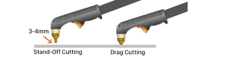
2.2Stand-Off Cutting
- Principle: The torch nozzle maintains a distance of 3-4 mm from the workpiece surface while cutting.
- Consumables: Requires a cutting nozzle that matches the machine’s current.
Auxiliary Tools:- Stand-off guide rails
- Roller guide rails
- Arc cutting guide kits, etc.
- Operating Tips:
- Start cutting from the side farthest from the operator and pull the torch toward the operator.
- Keep the torch perpendicular to the workpiece and move at a consistent, steady pace to ensure a neat cut.
- Applicable Scenarios: Ideal for finer cuts with good control.
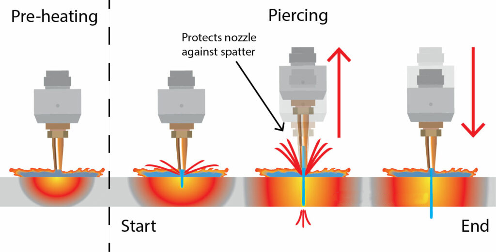
2.3Piercing
- Definition: Quickly creating a hole in the workpiece to prepare for subsequent cutting.
- Consumables: Use a standard cutting nozzle, ensuring the machine’s current matches the nozzle specifications.
- No Special Auxiliary Equipment Required
- Piercing Tips:
- Thin Sheets (<2mm):
- Tilt the torch at an angle of 15°–30° with the nozzle touching the workpiece.
- After establishing the arc, gradually transition to a vertical 90° position.
- After piercing, start the normal cutting process.
- Thick Sheets (≥2mm):
- Keep the torch perpendicular to the workpiece, with a distance of at least 12 mm.
- After establishing the arc, slowly move the torch toward the workpiece until the cutting arc is established.
- Once the arc penetrates the bottom of the workpiece, lower the torch to the normal cutting height and begin the cutting process.
- Thin Sheets (<2mm):
2.4Bevelling
- Purpose: To create an angled cut on the edges of plates or pipes to facilitate deeper weld penetration during welding.
- Applicable Thickness: Typically used for materials ≥ 9 mm thick.
- Cutting Nozzle: Use a standard cutting nozzle, ensuring the machine’s current matches the nozzle’s rated current.
- Operating Tips:
- For manual bevelling, use roller guide rails and angle guides to maintain consistent bevel angles.
- Common bevel angle range: 15° to 45°.
- Keep the nozzle 3-6 mm from the workpiece.
Recommended Reading:What Is Tube Bevel Cutting? Methods and Machine Guide
2.5Gouging
- Definition: Forming a smooth groove on the workpiece surface, often used for removing welds or preparing the back side of a workpiece for welding.
- Consumables and Equipment:
- Requires a specialized gouging nozzle.
- Should be used with a shielding cup and gas distributor.
- Operating Process:
- Maintain a 12 mm distance from the workpiece and a tilt of 20°–40°.
- After establishing the arc, slowly bring the nozzle close to the workpiece until the arc shifts to the main arc.
- Maintain a 20°–40° tilt, and once the arc stabilizes, move the nozzle back to about 15 mm away.
- Move forward at a constant, steady speed to create a narrow U-shaped groove (approx. 6 mm wide x 6 mm deep). The groove width can be adjusted by moving the nozzle left and right.
- Protective Measures:Use an arc protection shield, gouging shield, and torch protection cover to protect the equipment.
- Applicable Materials: All conductive metals.
2.6Cut Quality
The quality of plasma cutting edges can rival that of oxy-fuel cutting, but because plasma cutting involves melting the material, the upper edge of the cut typically exhibits:
- A larger molten area
- Uneven edges
- Rounded or beveled top corners
To improve cutting quality, torch manufacturers continually develop better torch designs to enhance arc constriction, achieving more uniform heating across the cut and improving overall cut quality.
2.7Cutting Posture and Parameters
- Torch Angle:
The torch should be perpendicular to the workpiece surface during cutting.
When the torch is mechanically clamped, a square gauge can be used to ensure verticality. - Torch to Workpiece Distance (Stand-Off Distance):
The distance between the torch nozzle and the workpiece directly affects the bevel angle. The greater the distance, the larger the bevel angle.
Low-current handheld systems (≤40A) typically use drag cutting, where the nozzle directly contacts the workpiece.
For high-current handheld systems, it is recommended to use drag shields, guides, or cutting guides to maintain a consistent distance.
Automatic cutting systems usually come equipped with an Arc Voltage Control (AVC) system, also known as “torch height control.”
AVC adjusts the torch height by monitoring the arc voltage, ensuring the nozzle maintains a constant distance from the workpiece, compensating for deformations, uneven surfaces, and table height variations, thus ensuring cutting consistency and quality.
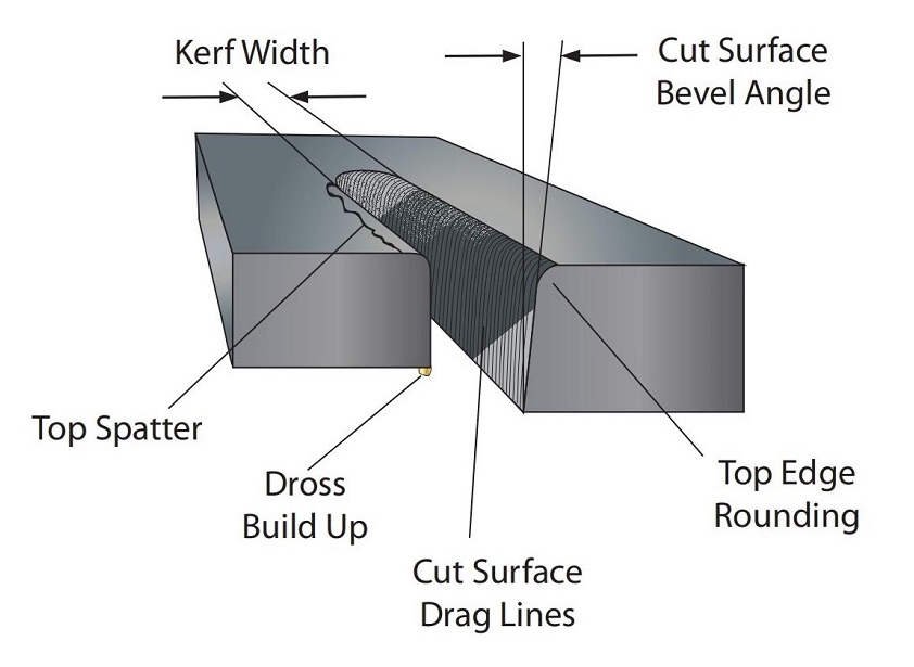
2.8Kerf Width
- Definition: The gap left in the material during cutting is referred to as the kerf.
- Importance: The width of the kerf affects the dimensional accuracy of the final product. External dimensions may shrink, and internal hole sizes may increase, so kerf compensation should be considered during design and programming.
- Factors Affecting Kerf Width:
- Cutting Current: Higher current increases the nozzle orifice size, resulting in a wider kerf.
- Cutting Speed: If the speed is too slow, the material will be fully melted, and the cutting arc may extend forward or sideways, causing the nozzle orifice to expand and the kerf to widen, along with more spatter (dross) and reduced cut quality.
- Typical Range: The kerf width is typically 2-3 times the nozzle orifice diameter.
2.9Bevel Angle
- Definition: Ideally, the cut should be perpendicular, but plasma cutting typically results in a certain tilt, known as the bevel angle.
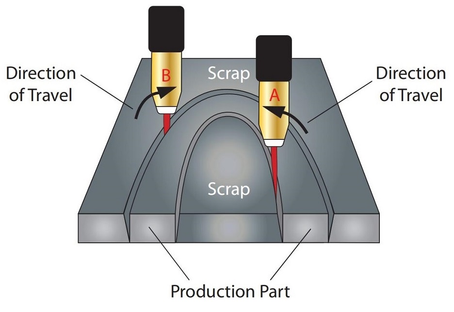
- Cause:The cutting gas, when ejected from the nozzle, carries a clockwise rotational vortex, which makes one side of the cut more vertical, while the other side tends to tilt.
Cutting Direction Importance:
For circular cuts:
-
- If the product is an internal round hole, the cutting direction should be clockwise.
- If the product is an external circle, the cutting direction should be counterclockwise.
2.10Dross
- Definition: Dross refers to slag and unmelted material that accumulate on the backside of the workpiece during cutting.
- Causes:
- Mismatched cutting parameters (cutting speed, current, arc voltage, gas pressure/flow, and gas type).
- High-Speed Spatter: Occurs when cutting too fast, making it difficult to clean and requiring grinding for removal.
- Low-Speed Spatter: Occurs when cutting too slowly, but is easier to remove with a brush or by tapping.
2.11Top Edge Rounding
- Definition: The rounding or wear of the top edge of the cut surface.
- Causes:
- Occurs when the current is too high or the nozzle is too far from the workpiece.
- Commonly seen during thick plate cutting.
3.0Plasma Cutting Common Applications and Specific Product Applications
3.1Common Applications:
- Metal Sheet Cutting: Plasma cutting is widely used for cutting metal sheets of steel, aluminum, copper, and other materials. Due to its high precision and fast cutting speeds, it is ideal for applications in industrial sectors where strict shape and size requirements are necessary.
- Pipe Cutting: Plasma cutting is not only suitable for sheet metal but also for precise cutting of various pipes, especially thick-walled and large-diameter pipes.
- Welding Preparation: Plasma cutting is commonly used for edge bevelling or pre-treatment of metal parts, especially in welding processes, where bevel cuts can enhance weld joint quality and penetration depth.
- Groove and Slot Cutting: Plasma cutting can be used for creating grooves on metal surfaces, often seen in welding or repair processes.
- Metal Sheet Piercing: Plasma cutting can quickly punch holes in metal sheets, preparing them for subsequent processing, especially suitable for thinner metal sheets.
3.2Specific Product Applications:
- Plasma Plate Cutting Machines:
These machines are designed for cutting large metal sheets and are widely used in industries such as shipbuilding, steel structures, and automotive manufacturing. Plasma plate cutting machines can cut metal sheets of various thicknesses with high speed and precision, showcasing their advantages in efficient and refined production. - Plasma Pipe Cutting Machines:
These machines are specifically designed for cutting pipes, especially large-diameter or thick-walled pipes. Plasma pipe cutting machines are commonly used in industries such as construction, energy, oil, and natural gas, where they cut irregular pipes, equipment, and structural components, offering high production capacity. - Plasma Cutting Robots:
Compared to traditional handheld plasma cutters, plasma cutting robots offer high automation and precision. They are commonly used in cutting complex parts, especially in industries such as aerospace and automotive manufacturing, significantly improving production efficiency and cutting accuracy. - CNC Plasma Cutting Machines:
These cutting machines utilize CNC technology to precisely control the cutting path, making them suitable for batch production and cutting complex shapes. CNC plasma cutting machines are widely used in sheet metal processing, advertising industries, and machinery manufacturing, providing efficient and precise cutting solutions. - Portable Plasma Cutting Machines:
These machines are ideal for on-site operations, especially for cutting large metal structures or workpieces. Their flexibility makes them widely used in industries such as ship repair and construction.
4.0Plasma Cutting FAQ
4.1How does plasma cutting compare to oxy-fuel cutting?
While both methods are used for cutting metals, plasma cutting is faster, more precise, and produces less heat, resulting in a smaller heat-affected zone. Oxy-fuel cutting is better for thicker materials, while plasma cutting is ideal for a wide range of thicknesses, from thin sheets to thick plates.
4.2What is dross, and how can it be minimized?
Dross is the molten material that accumulates on the back of the workpiece during cutting. It is caused by incorrect cutting parameters, such as speed, current, and gas pressure. To minimize dross, adjust the cutting speed, ensure the correct gas pressure, and avoid cutting too slowly or too quickly.
4.3What is the difference between drag cutting and stand-off cutting?
- Drag Cutting: The torch nozzle is dragged along the workpiece surface and is ideal for low-current applications (≤40A).
- Stand-Off Cutting: The torch nozzle is kept 3-4 mm away from the workpiece, suitable for higher precision and finer cuts. This method requires additional equipment like stand-off guide rails.
4.4What is the ideal cutting distance between the torch and the workpiece?
The distance between the torch nozzle and the workpiece, known as the stand-off distance, affects the cut quality. For low-current systems, the nozzle often touches the material (drag cutting), while for higher current systems, the nozzle remains at a constant distance using guides or automated systems like AVC (Arc Voltage Control).
4.5What is kerf width, and how does it affect my cut?
Kerf width refers to the gap left in the material during cutting. It can affect the accuracy of the final product, especially for complex shapes and hole cutting. Larger currents and slower cutting speeds increase kerf width, so it must be considered during the design phase to compensate for dimensional changes.
4.6What is beveling, and when should it be used?
Beveling is the process of cutting the edge of a metal sheet or pipe at an angle, usually between 15° to 45°. It is commonly used in welding preparation to ensure proper weld penetration and joint quality.