- 1.0Manual Cutting of Aluminum: Basic Practical Guide
- 2.0Saw-less Cutting of Aluminum: Non-Sawing Technical Solutions
- 3.0Precise Cutting Solutions by Aluminum Type
- 4.0Circular Saw Cutting of Aluminum: Technical Details
- 5.0Professional Cutting Equipment: Classification and Selection
- 6.0Safety Operating Standards and Quality Control Points
- 7.0Conclusion
Introduction
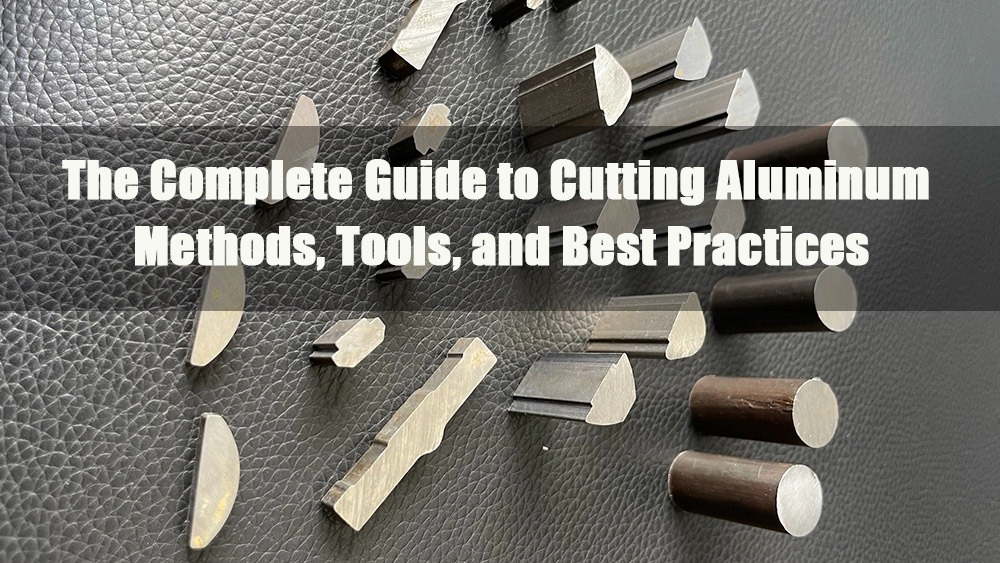
Aluminum is characterized by its low density, high strength, corrosion resistance, and excellent electrical and thermal conductivity. It is widely used in construction, aerospace, automotive, electronics, and household applications. Cutting is the core preliminary process in aluminum fabrication, directly determining dimensional accuracy, edge quality, production efficiency, and cost. This article focuses on “How to Cut Aluminum,” breaking down two fundamental approaches: manual cutting and saw-less cutting.
1.0Manual Cutting of Aluminum: Basic Practical Guide
Manual cutting requires no electricity and has a low barrier to entry. It is suitable for small-batch processing, on-site emergency repairs, or scenarios lacking professional equipment. The core objectives are controlling cut straightness and minimizing burrs.
1.1Tool Selection and Preparation
- Core Tools: High-Speed Steel (HSS) fine-toothed hacksaw blades (18-24 TPI); carbide-tipped blades are optional for hard aluminum alloys. Additional tools include a vise (with rubber-padded jaws), tape measure (accuracy ≥1mm), marker, square/angle ruler, medium/fine-toothed files, and aluminum cutting fluid or kerosene.
- Safety Protection: Wear cut-resistant gloves, safety goggles, and long-sleeved work clothes to avoid skin exposure to the cutting area.
- Securing the Aluminum: Place the aluminum in the vise with the cutting line parallel to the jaws and clamp with moderate pressure. For long, slender stock exceeding 1m, add support points to prevent bending or deformation.
1.2Operational Steps
- Measurement and Marking: Use a tape measure to determine dimensions (tolerance ±0.5mm). Use a square/angle ruler to scribe the line 2-3 times. For round or irregular stock, ensure the marking forms a closed loop.
- Positioning the Cut: Hold the hacksaw at a 45°-60° angle to the cutting surface. Lightly stroke 3-5 times to create a pilot groove (kerf) and prevent blade wandering.
- Steady Cutting: Keep the blade flat against the pilot groove. Advance at 10-15 strokes per minute with moderate pressure (avoid bending the blade). Apply cutting fluid every 3-5 strokes to reduce heat and prevent galling (blade binding).
- Finishing the Cut: When the cutting depth reaches 2/3, slow down and reduce pressure. For hollow tubes or thin-walled materials, support the piece being cut off just before completion and gently snap it off.
- Deburring: Use a medium-toothed file for unidirectional deburring, then refine with a fine-toothed file. Aim for a surface roughness of Ra ≤ 6.3μm.
1.3Applicable Scenarios and Precautions
- Scope of Application: Aluminum plates (thickness ≤5mm), thin-walled tubes (OD ≤30mm), aluminum angle iron (section ≤50mm), and profiles (length ≤1m). Suitable for small-batch (≤10 pieces) processing.
- Precautions:
- Do not use coarse-toothed blades (≤14 TPI)
- Avoid excessive force to prevent blade breakage
- Use a brush to clean aluminum chips (never bare hands)
- For hard aluminum alloys (7075 series), shorten single cutting times and increase cutting fluid frequency
2.0Saw-less Cutting of Aluminum: Non-Sawing Technical Solutions
Saw-less cutting includes tool machining, laser, plasma, waterjet, and shearing methods—suitable for scenarios ranging from household emergencies to industrial precision machining.
2.1Core Technology Comparison Table
| Cutting Method | Applicable Scenario | Dimensional Accuracy | Cutting Efficiency | Equipment Cost | Core Advantage | Safety Points |
| Tool Machining | Thickness ≤3mm plates, thin-walled tubes, fine cuts | ±0.2-0.5mm | Low (Manual) / Medium (Mechanical) | Low – Medium | Smooth cut, no thermal deformation | Control force in manual scraping; use coolant for mechanical cutting |
| Laser Cutting | 0.1-20mm materials (all types), complex shapes, mass production | ±0.05-0.1mm | High (10-20x manual) | High | Non-contact, small Heat Affected Zone (HAZ) | Wear laser safety glasses; ventilate aluminum dust |
| Plasma Cutting | ≥6mm plates, thick-walled tubes, low-precision industrial work | ±0.5-1mm | Medium – High | Medium | Efficient for thick stock, moderate cost | Keep away from flammables; wear flame-retardant gear and mask |
| Waterjet Cutting | ≥10mm thick plates, sensitive alloys, high-precision complex shapes | ±0.05-0.1mm | Medium | High | No thermal deformation, eco-friendly, no dust | Protect high-pressure hoses; seal abrasive storage |
| Shearing | ≤1mm thin plates, foil, straight-line batch cutting | ±0.3-0.8mm | High (Straight cuts) | Low – Medium | Convenient operation, low cost | Adjust blade clearance to prevent material wrinkling |
2.2Detailed Operations for Saw-less Methods
- Tool Machining:
- Manual: Use an aluminum-specific carbide scraper (remove ≤0.5mm per pass, unidirectional)
- Mechanical: Use lathe/mill with aluminum-specific carbide tools (Rake angle 15°-20°, Relief angle 5°-8°)
- Speed settings: 100-300m/min (soft aluminum); lower values (hard aluminum)
- Always use cutting fluid
- Laser Cutting:
- Equipment: Fiber laser cutter (wavelength 1064nm)
- Power settings: 500-1000W (≤3mm); 1000-3000W (3-10mm); 3000-6000W (10-20mm)
- Cutting speed: 2-15m/min
- Focus: 0.5-1mm below surface
- Auxiliary gas: Nitrogen (pressure 0.3-0.8MPa) to prevent oxidation
- Plasma Cutting:
- Equipment: Air plasma or dedicated aluminum plasma cutter
- Gas: Argon or Argon-Hydrogen mix (8:2)
- Current settings: 60-80A (6-10mm); 80-120A (10-20mm)
- Cutting speed: 300-800mm/min
- Nozzle standoff: 5-10mm
- Waterjet Cutting:
- Pressure: 300-400MPa
- Abrasive: 80-120 mesh size
- Cutting speed: 100-500mm/min (slower for thicker materials)
- Post-operation: Clean wastewater and waste abrasive; ensure high-pressure protection
- Shearing:
- Manual: Use tin snips (cut wide sheets in sections ≤50mm)
- Mechanical: Adjust blade clearance (5%-10% of aluminum thickness); ensure hold-downs clamp tightly
3.0Precise Cutting Solutions by Aluminum Type
3.1Adaptation Table for Various Aluminum Cutting Scenarios
| Aluminum Type | Specifications | Recommended Method | Core Tools / Equipment | Critical Operation Points |
| Aluminum Sheet | Thin (≤1mm) | Manual shearing, Electric shears, Laser cutting | Tin snips, 500-1000W Fiber Laser | Shearing: Prevent bending. Laser: Use Nitrogen; lightly sand edges |
| Aluminum Plate | Medium (1-6mm) | Hand saw, Circular saw, Laser, Plasma | Fine-tooth hand saw, 60-80T Aluminum circular blade | Hand saw: Clamp tightly. Circular saw: RPM 2000-3000 |
| Aluminum Plate | Thick (≥6mm) | Waterjet, Plasma, High-power Laser | Waterjet, Plasma cutter, 3000W+ Laser | Waterjet: Add abrasive. Plasma: Maintain uniform nozzle speed |
| Aluminum Tube | Thin Wall (≤2mm) | Hand saw + V-block, Laser, Tube cutter | Fine-tooth saw, V-block, 1000-2000W Laser | Fill tube with wood chips; ensure blade perpendicularity |
| Aluminum Tube | Thick Wall (≥2mm) | Carbide hand saw, Lathe, Cold saw | Carbide-tipped saw, Lathe, Specialized pipe cutter | Gently snap off before full cut to prevent chipping |
| Aluminum Profile | Window/Door / Industrial | Hand saw, Circular saw, Miter saw | Fine-tooth saw, Aluminum blade, Miter saw | Rubber-wrap vise jaws; use guide rails for circular saws |
| Aluminum Angle | Thin (≤5mm) | Hand saw, Circular saw | Fine-tooth saw, Angle-adjustable circular saw | Calibrate angle with square; use circular saw for batches |
| Aluminum Angle | Thick (≥5mm) | Circular saw, Plasma, Laser | Aluminum circular blade, Plasma cutter | Enhance cooling to prevent thermal cracking |
| Aluminum Alloy | Soft (6061/5052) | Hand saw, Circular saw, Laser, Machining | Fine-tooth saw, Aluminum blade, Laser | Increase cutting speed; use cutting fluid to prevent galling |
| Aluminum Alloy | Hard (7075/2024) | Laser, Waterjet, Carbide circular saw | 3000W+ Laser, Waterjet, Hard alloy blade | Reduce cutting speed; Coolant flow rate ≥5L/min |
3.2Supplementary Specialized Cutting Techniques
- Profile Cutting:
- Calibrate angles (45°/90°) with angle ruler
- Securely clamp to avoid hollow section crushing
- Industrial grade: Use dedicated aluminum cutting machine (45° miter joint error ≤±0.1°)
- Hard Alloy Cutting:
- Inspect for micro-cracks with magnifying glass post-cut
- Laser cutting: Increase power, decrease speed
- Do not use standard hacksaw blades
4.0Circular Saw Cutting of Aluminum: Technical Details
Circular saw cutting is ideal for medium-volume straight-line cutting. Success depends on blade selection, RPM control, and cooling/lubrication.
4.1Core Parameters for Circular Saw Cutting
| Aluminum Type / Thickness | Blade Selection (Teeth / Material) | RPM (r/min) | Feed Rate (mm/min) | Coolant Requirements | Applicable Scenario |
| Thin Plate (1-3mm) | 80T / Carbide-tipped Aluminum Blade | 3000-3500 | 80-100 | Continuous spray (prevent galling) | Mid-volume straight cuts |
| Medium Plate (3-6mm) | 60-80T / Carbide-tipped Aluminum Blade | 2500-3000 | 50-80 | Continuous spray (cool blade) | Mid-volume processing, construction |
| Thin Tube (≤2mm) | 80T / Carbide-tipped Aluminum Blade | 2500-3000 | 30-50 | Frequent small applications (avoid accumulation) | Window/Door fabrication |
| Profiles (Section ≤80mm) | 60-70T / Carbide-tipped Aluminum Blade | 2000-2500 | 40-60 | Continuous spray; clear cavity chips | Structural frames, architectural |
| Soft Alloy (6061) | 60-80T / Carbide-tipped Aluminum Blade | 2500-3500 | 60-90 | Standard lubrication (prevent sticking) | General mid-volume machining |
| Hard Alloy (7075) | 70-80T / Coated Carbide Blade | 1500-2000 | 30-50 | High-flow spray (aggressive cooling) | Precision parts machining |
4.2Operational Steps
- Parameter Setup: Select blade, RPM, and feed rate per table. Use higher RPM for soft aluminum; lower RPM for hard alloys/thick stock.
- Fixturing: Securely clamp aluminum to workbench. Align cutting line with guide rail. Add supports for long/slender stock.
- Cutting Operation: Start saw and wait for full RPM before advancing. Feed steadily while continuously spraying cutting fluid. Avoid extended high-speed idle operation.
- Post-Processing: Wait for blade to stop completely before removing material. Deburr with file and clean chips from blade teeth.
4.3Precautions
- Blade Maintenance: Regularly inspect; replace if worn or chipped.
- Tool Compatibility: Never use woodworking blades for aluminum.
- Fluid Maintenance: Change cutting fluid regularly to maintain effectiveness.
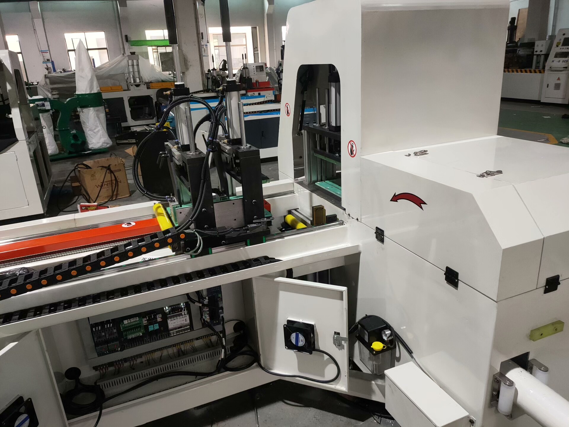
5.0Professional Cutting Equipment: Classification and Selection
Aluminum cutting machines are classified by automation level and cutting principles, designed for large-scale, high-precision processing.
5.1Classification by Automation Level
Manual Aluminum Cutting Machine
- Core Structure: Cast iron frame + manual vise + carbide blade (300-400mm) + simple cooling nozzle
- Key Parameters: Cutting angle 0°-45° (tolerance ≤±0.2°), dimensional accuracy ±0.1-0.3mm, suitable for ≤10mm plates / ≤80mm tubes
- Applicable Scenarios: Small batches (≤50 pieces/batch), custom orders, on-site installation
- Advantages: Simple structure, small footprint, low investment, easy maintenance
Semi-Automatic Aluminum Cutting Machine
- Core Structure: Pneumatic/hydraulic clamping + automatic feed rail + circulating cooling system
- Key Parameters: Angle tolerance ≤±0.15°, dimensional accuracy ±0.08-0.2mm, efficiency 30-80 pieces/hour
- Applicable Scenarios: Medium batches (50-300 pieces/batch), standardized profile processing (door/window frames, tubes)
- Advantages: 2-3x efficiency increase, stable accuracy, reduced labor intensity
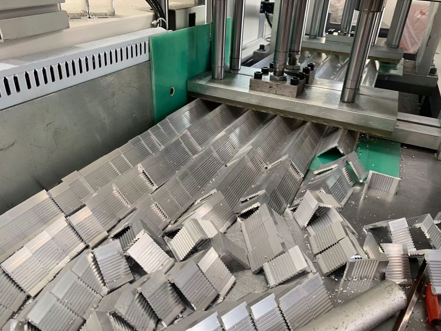
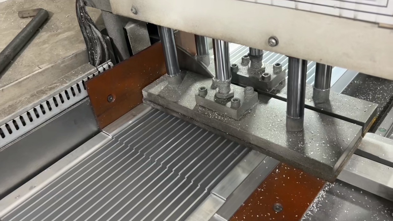
Fully Automatic Aluminum Cutting Machine
- Core Structure: PLC control system + servo feeding + automatic loading/unloading + waste collection
- Key Parameters: Angle tolerance ≤±0.1°, dimensional accuracy ±0.05-0.1mm, efficiency 100-300 pieces/hour
- Applicable Scenarios: Large batches (≥300 pieces/batch), precision parts (automotive components, curtain wall keels)
- Advantages: 24-hour continuous operation, high precision consistency, flexible manufacturing compatible
5.2Core Selection Recommendations
- Maintenance Considerations:
- Regularly inspect blades, nozzles, and cutting heads for wear or damage
- Replace cutting fluid and filters per manufacturer recommendations (typically every 3-6 months for industrial use)
- Calibrate guide rail precision quarterly to maintain dimensional accuracy
- Clean chip collection systems weekly to prevent equipment jamming
6.0Safety Operating Standards and Quality Control Points
6.1Safety Operating Standards
- Mandatory Protective Equipment:
- All operations: Cut-resistant gloves + safety goggles
- Laser/plasma cutting: Specialized wavelength-compatible protective glasses/face shields
- High-dust environments (laser/plasma): N95+ dust mask
- Plasma cutting: Flame-retardant workwear + heat-resistant gloves
- Pre-Operation Tool Inspection:
- Hacksaw blades: Check for tightness and absence of cracks
- Circular saws: Verify blade mounting security and guard functionality
- Power equipment: Inspect wiring, cooling systems, and emergency stop buttons
- Cutting fluids: Ensure proper fluid level and compatibility with aluminum
- Work Environment Requirements:
- Maintain ventilation (especially critical for laser/plasma cutting to remove aluminum dust and fumes)
- Keep work area dry and free of oil, debris, and flammable materials
- Equip laser/plasma workstations with dry powder fire extinguishers (Class D for metal fires)
- Mark clear safety zones around operating equipment (minimum 1.5m radius)
- Operational Prohibitions:
- No cutting without full protective gear
- No processing unclamped or unstable workpieces
- No touching rotating blades, cutting heads, or hot workpieces during/immediately after cutting
- No unauthorized operation of professional equipment (only trained personnel permitted)
- No modifying safety guards or emergency stop systems

6.2Quality Control Points
- Dimensional Accuracy Assurance:
- Calibrate measuring tools (tape measure, calipers, angle ruler) before each shift
- Conduct sampling inspections every 10 pieces for batch processing (100% inspection for high-precision parts)
- Tolerance benchmarks:
- Manual cutting: ≤±0.5mm
- Semi-automatic equipment: ≤±0.2mm
- Fully automatic/precision cutting (laser/waterjet): ≤±0.1mm
- Cut Quality Standards:
- Visual inspection: Cut edges must be vertical (perpendicularity tolerance ≤0.1mm/m) and free of obvious burrs, chipping, or dross
- Surface requirements: No scratches, indentations, or pressure marks on aluminum surfaces
- Structural integrity: No micro-cracks (especially critical for hard alloys like 7075)
- Post-Processing Requirements:
- Deburr immediately after cutting (use files, deburring tools, or abrasive pads)
- For weld-ready parts: Remove oxide layer from cut edges (sandpaper or wire brush)
- Clean all workpieces to remove cutting fluid residue and aluminum chips
- Material Protection:
- Avoid prolonged exposure to humid environments (aluminum oxidizes rapidly)
- Wrap precision components in protective film to prevent scratches during storage/transport
- Separate finished parts from raw materials to prevent contamination
7.0Conclusion
The tables and technical parameters provided throughout this guide serve as quick-reference tools to match cutting methods with specific aluminum types, thicknesses, and production requirements. By combining the right equipment, proper technique, and rigorous safety/quality protocols, fabricators can achieve optimal cutting results—maximizing efficiency, minimizing waste, and ensuring workpiece integrity.
As technology advances, aluminum cutting continues to evolve toward higher precision, greater automation, and more eco-friendly processes (e.g., low-waste laser cutting, biodegradable cutting fluids). The adoption of professional, application-specific equipment will remain a key driver of productivity and quality in aluminum fabrication across industries.