- 1.0Common Applications: Angles in Bending over Openings
- 2.0Torsional Effects: Why Hollow Sections Are Preferable
- 3.0Angle Sections in Compression: A More Predictable Behavior
- 4.0Angle Sections in Bending: Limitations in Code Guidance
- 5.0Interaction Checks: Comparison Between BS 5950 and Eurocode
- 6.0Unequal Angle Sections: Added Complexity and Limitations
- 7.0Conclusion: Use Angles in Bending Only with Caution
Angle sections are widely used in structural engineering due to their economy and ease of fabrication. However, when it comes to using angles in bending, particularly unrestrained bending, significant challenges emerge. Although they are frequently chosen to support loads over openings—such as brickwork lintels—their torsional instability and complex stress response make them a risky choice.
This article presents a detailed overview of how angle sections behave in bending, the limitations of design guidance under both BS 5950 and Eurocode 3 (EN 1993-1-1), and why alternative profiles are often a more reliable and structurally sound solution.
1.0Common Applications: Angles in Bending over Openings
Angle sections in bending are most commonly used in domestic construction to support masonry above door and window openings. Although the detail may seem simple, it introduces eccentric loading and torsional behavior that can lead to serviceability issues, such as façade cracking.
The key structural challenge lies in the fact that when subjected to bending, especially without full lateral restraint, the compressed leg of the angle tends to deflect out of plane, causing the member to twist. This phenomenon is exacerbated by the typical eccentric application of the vertical load, which generates a moment around both the vertical and horizontal axes.
2.0Torsional Effects: Why Hollow Sections Are Preferable
Any structural member carrying an eccentric load will twist. This is not unique to angles, but the low torsional stiffness of angle sections makes them particularly susceptible. In such cases, using a closed hollow section (like a square or rectangular HSS) offers a superior alternative. Though these sections may be more expensive and involve more complex detailing at the connections, the reduction in torsional deformation is often worth the trade-off.
In practical applications such as domestic extensions or lintels, closed sections can greatly enhance durability and minimize visible defects in the finished structure.
3.0Angle Sections in Compression: A More Predictable Behavior
When angle sections are used in compression (e.g., as part of a truss), their behavior is well understood. Unlike buckling about major or minor rectangular axes, angles buckle about their principal axes: the u–u and v–v axes. This results in each leg of the angle trying to buckle in its own out-of-plane direction, creating a torsional mode of buckling.
Design codes such as BS 5950 Clause 4.7.10 and EN 1993-1-1 Section BB.1.2 provide formulas to calculate slenderness based on this mode. The calculation adjusts for torsional effects and considers whether the angle has end restraints, which significantly influence buckling capacity.
4.0Angle Sections in Bending: Limitations in Code Guidance
BS 5950 Design Guidance for Bending
Clause 4.3.8 in BS 5950 provides both a basic and a simplified method for calculating the buckling resistance moment (Mb) for angle sections. The simplified method is limited to equal angles bent about their x–x axis, typically under vertical loads across spans like window openings.
Sample Calculation Using BS 5950 Simplified Method:
Given:
Section: 150×150×12 mm
Span: 4 m
Steel Grade: S275
ε = 1.0 (based on steel yield strength)
Radius of gyration (rv) = 29.5 mm
Section modulus Zx = 67.7×10³ mm³
The simplified formula is:
This result shows a relatively low resistance, emphasizing the importance of understanding the limits of this approach.
EN 1993-1-1 (Eurocode 3) Approach: More Complex, Less Direct
The Eurocode does not offer a direct method for evaluating bending resistance of angles. Instead, it recommends resolving the applied bending moment into the principal axes (u–u and v–v) and verifying the member using an interaction equation. This adds complexity, especially for unequal angles.
The key step is to compute the relative slenderness:
lambda_LT = (0.72 × v_a × f_y) / (E × phi_a × lambda_v)
Where:
- lambda_LT is the lateral-torsional slenderness ratio
- v_a is the shear correction factor
- f_y is the yield strength of the material
- E is the elastic modulus
- phi_a is the slenderness coefficient (typically 3.77)
- lambda_v is the shear slenderness ratio (e.g., L / r_v)
Where:
φₐ is the slenderness coefficient (typically 3.77)
vₐ is derived using a formula based on λᵥ and the monosymmetry index ψₐ
λᵥ = L / rᵥ = 4000 / 29.5 = 135.6
For an equal angle (ψₐ = 1), this yields:
vₐ ≈ 0.984 → λ_LT = 0.580 → χ_LT = 0.724
Using second moment of area and elastic modulus:
Iu = 1170 cm⁴
Extreme fibre distance = 106 mm
Wu = (1170 × 10⁴) / 106 = 110 × 10³ mm³
Mb = 0.724 × 275 × 110 × 10³ = 21.9 kNm
5.0Interaction Checks: Comparison Between BS 5950 and Eurocode
Assume an applied moment of 14 kNm resolved equally into principal axes:
Given:
Mu = Mv = 9.9 kNm
Wv = 52 × 10³ mm³
Wu = 110 × 10³ mm³
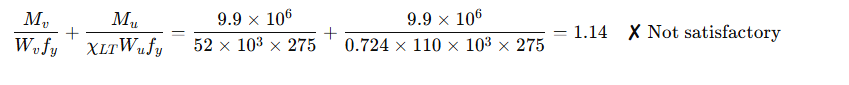
Eurocode Interaction Check:

BS 5950 Interaction Check:
Using buckling resistance Mb = 26 kNm:
Interaction = 1.07 ✓ Acceptable, but borderline
Using simplified method (Mb = 13.9 kNm):
Interaction = 1.01 ✘ Exceeds limit
6.0Unequal Angle Sections: Added Complexity and Limitations
Fabrication Considerations for Angle Sections
In addition to the structural complexity of using angle sections in bending, fabrication also presents challenges—particularly when precise hole placement, end preparation, or notching is required. To achieve accurate modifications, especially for unequal angle sections or intricate connections, fabricators often rely on an ironworker machine. These machines allow for efficient shearing, punching, and coping of steel angles in a single setup, saving time while ensuring repeatability.
For applications involving fine detailing or internal corner cuts—such as when preparing angles for clean connections to plates or gussets—a sheet metal corner notcher is frequently used. This tool allows for precise corner trimming, enabling better fit-up and alignment during assembly. Using the correct fabrication equipment not only improves efficiency but also ensures that the structural performance predicted in the design is maintained through to installation.
BS 5950 does not allow the simplified method for unequal angles. Designers must use the basic method and resolve moments into principal axes. While properties such as centroid location, I<sub>u</sub>, and I<sub>v</sub> can be found in published tables, it requires additional trigonometry, monosymmetry index calculation, and determination of effective section moduli.
For slender legs, section classification becomes critical:
BS 5950 Class 3 limit: 15ε
Eurocode Class 3 limit: 14ε (based on c/t)
For example, a 150×10 mm leg with c ≈ 128 mm gives:
c/t = 12.8 < 14ε = 12.9 → Just acceptable
Linking Structural Design and Shop Fabrication
Successful implementation of angle sections—especially in load-sensitive applications—depends not just on the theoretical design but also on practical fabrication accuracy. When structural members require precise cutting, notching, or punching, especially in custom or short-span applications, using the right equipment is essential. Tools like the ironworker machine and sheet metal corner notcher are commonly used to prepare angle steel efficiently and accurately, reducing on-site modification and ensuring better compliance with design intent.
If the section is Class 4, further complexity arises:
Use of effective section properties (Eurocode), or
Application of reduced design strength (BS 5950)
For combined bending and axial load, this can become impractically complex.
7.0Conclusion: Use Angles in Bending Only with Caution
This technical review highlights two critical design principles:
- Angles are not ideal for carrying significant moments—especially if unrestrained. Torsional behavior under eccentric or lateral loading can severely limit performance and lead to serviceability failures such as façade cracking.
- Designing unequal angles is labor-intensive and error-prone, particularly when dealing with Class 4 sections or combined loading scenarios.
Recommended Practice:
Use equal angle sections of at least Class 3 cross-section.
For unrestrained bending situations, consider substituting with a torsionally stiff section, such as a hollow section or I-beam.