- 1.0What Is a Stamping Press?
- 2.0Frame Types: C-Frame vs. Straight-Side Presses
- 3.0Mechanical Presses: Operation and Drive Systems
- 4.0Hydraulic Presses: Flexibility and Force Control
- 5.0Choosing the Right Press
- 6.0Benefits of Coil Processing
- 7.0Press Feeding Mechanisms
- 8.0Scrap Processing
- 9.0Applications of Stamping Presses Across Industries
- 10.0Conclusion
- 11.0Frequently Asked Questions (FAQ)
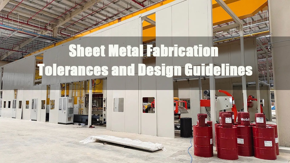
Stamping presses are at the heart of modern sheet metal fabrication, transforming flat materials into final products with precision, efficiency, and minimal waste. This comprehensive guide explores the major types of stamping presses, their core components, drive mechanisms, press selection criteria, and modern coil processing systems.
1.0What Is a Stamping Press?
Stamping presses utilize the force of a moving ram (or slide) to transmit tonnage to specific tooling in order to shape a product. This process often results in little or no scrap and requires minimal operator intervention. A broad array of press sizes and types is used depending on part complexity, geometry, and production scale.
The motion force of the press is powered either mechanically or hydraulically. Simple, one-dimensional stampings may be accomplished with compact benchtop presses generating as little as five tons. In contrast, large, complex components require presses with capacities in the thousands of tons. Press speed varies significantly, from 10 to 18 strokes per minute for standard applications to as fast as 1800 strokes per minute in high-speed systems.
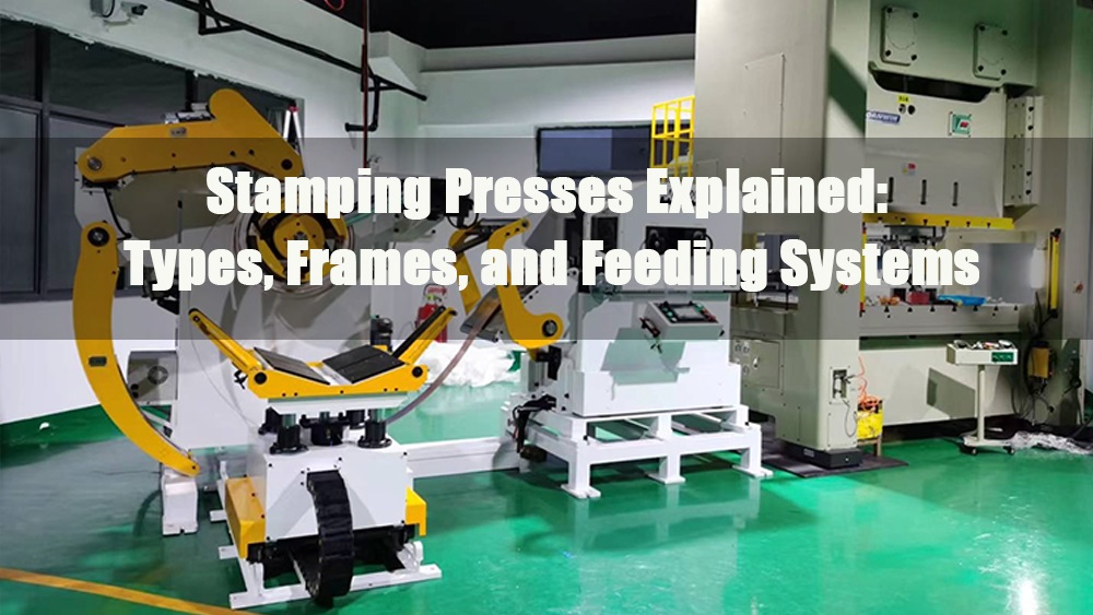
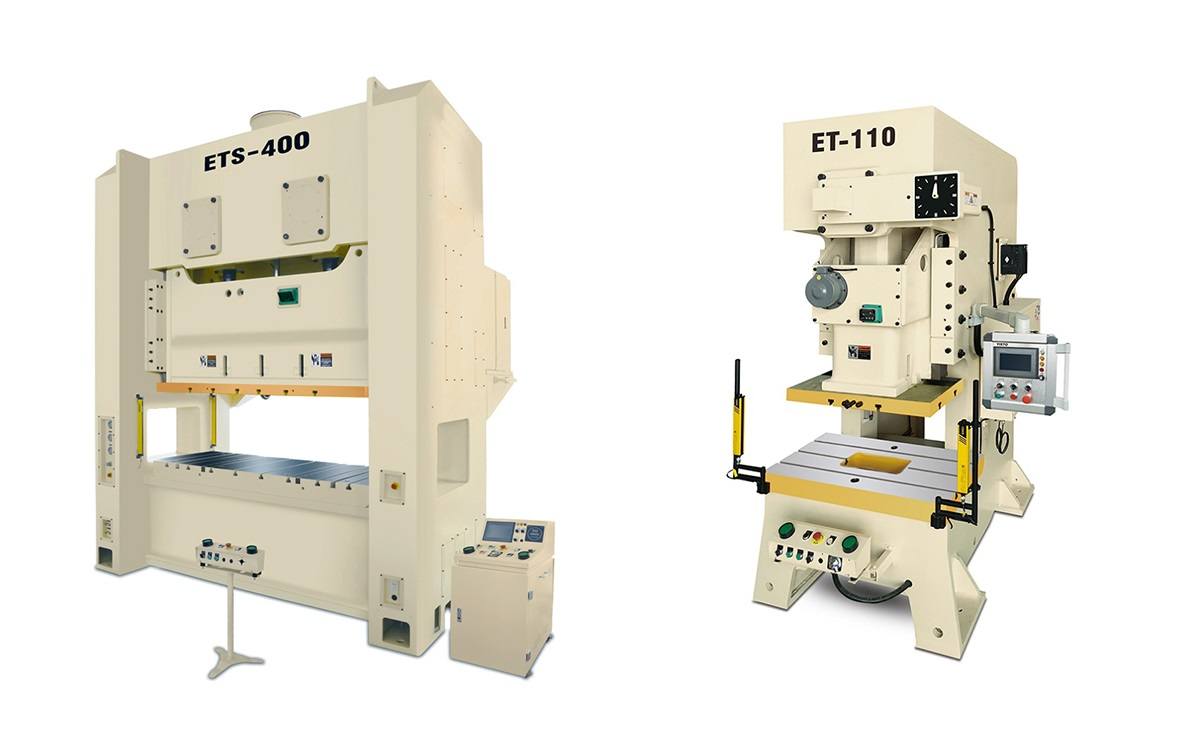
2.0Frame Types: C-Frame vs. Straight-Side Presses
Both hydraulic and mechanical presses are classified by the frame type on which the moving components are mounted. The two most common press frame types are:
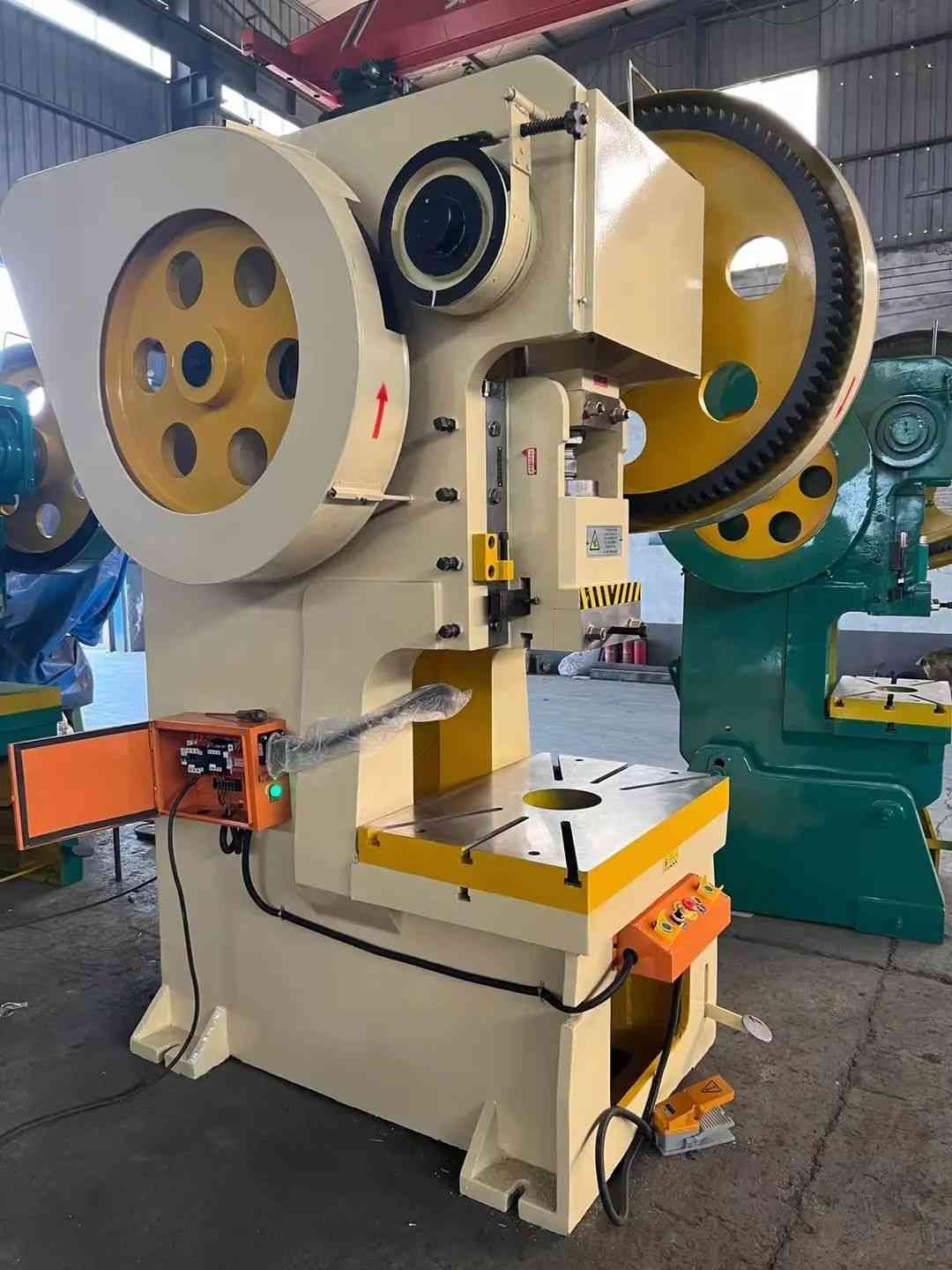
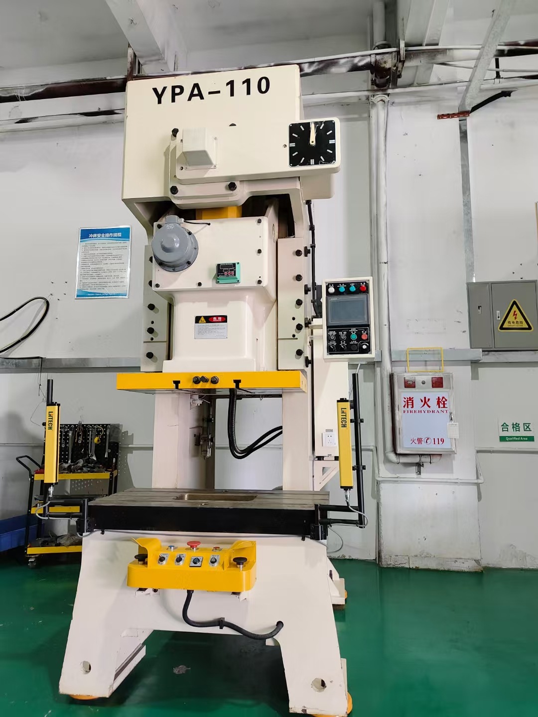
2.1Gap-Frame (C-Frame) Press
The “C” frame press allows easy access to three sides of the die area, requires less floor space, and is often more cost-effective, especially in ranges between 35 to 60 tons. However, due to its open frame, the C-frame is prone to angular misalignment as the structure deflects under load. Although not always problematic, this can necessitate heavier (and costlier) frames for certain applications.
A popular variant is the Open Back Inclinable (OBI) press, which tilts the frame backward for easier part or scrap ejection. Alternatively, the Open Back Stationary (OBS) press is more widely used and discharges parts or scrap using timed air blasts, mechanical devices, or conveyors.
2.2Straightside Press
Straight-side presses feature vertical columns or uprights that eliminate angular deflection. These provide superior die life and part accuracy.
The four principal components of a straight-side press include:
- Crown: Supports the motor, flywheel, and driving mechanisms
- Columns: Support the crown and include gibs for alignment and guidance
- Bed: Serves as the structural foundation
- Bolster: Mounted on the bed to support and strengthen the die setup
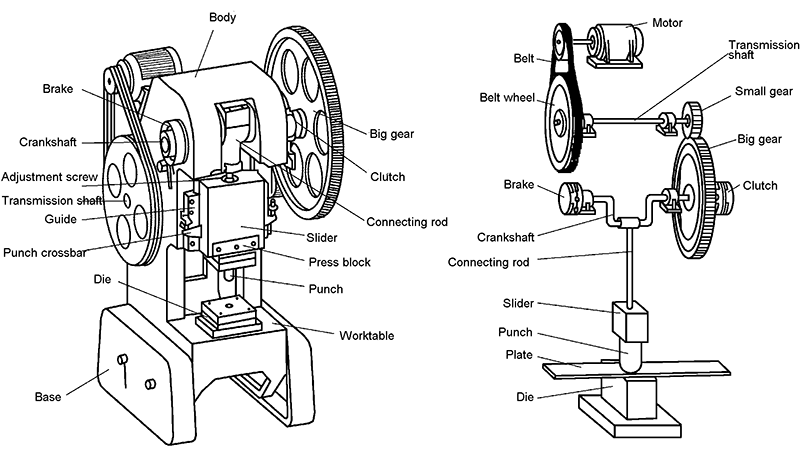
3.0Mechanical Presses: Operation and Drive Systems
Mechanical presses operate using an electric motor that turns a flywheel. The flywheel spins around a crankshaft until engaged by a clutch, transmitting energy via a drivetrain to the slide or ram.
3.1Key Components:
- Clutch: Transfers flywheel energy to the crankshaft
- Braking System: Holds the ram in position when disengaged
3.2Force Capacity
Force capacity refers to the tonnage exerted at a specified distance from the bottom of the stroke, influenced by:
- Flywheel speed
- Torque capacity of the drivetrain
Note: Gear ratios in geared presses do not increase force but help optimize flywheel speed to boost torque capacity.
3.3High-Speed Mechanical Presses
Presses capable of 300 strokes per minute or higher are considered high-speed. For small, high-volume production, speeds can reach up to 1400 strokes per minute.
3.4Drivetrain Variations
Three primary mechanical drive train arrangements exist:
3.5Direct-Drive System
- The drive motor rotates the flywheel directly via a belt system.
- Offers the highest speed, lower energy loss, and easy maintenance.
- Drawback: Must operate at maximum speed to achieve full forming force, and can cause angular misalignment due to torque on one crankshaft end.
3.6Geared Drive Systems
- Include single or double gear reductions and eccentric gear drives.
- Address angular misalignment.
- Offer greater power for forming large or deep-drawn parts.
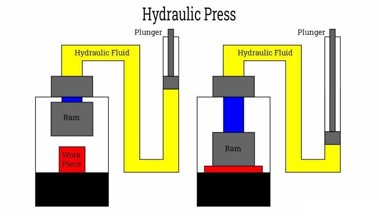
4.0Hydraulic Presses: Flexibility and Force Control
Although mechanical presses dominate the market, hydraulic presses are gaining popularity due to their flexibility.
4.1Advantages of Hydraulic Presses:
- Full tonnage is available at any stroke position.
- Ideal for deep drawing that requires force early in the stroke.
- Adjustable stroke improves part clearance between cycles.
- Preset pressure accommodates various die heights and material thicknesses.
Hydraulic presses enable better control, making them well-suited for applications involving large or irregular parts.
5.0Choosing the Right Press
There is no single press that meets all application needs. Selection involves trade-offs between performance, cost, and operational demands.
5.1Primary Selection Factors:
- Press size
- Force capacity
- Energy availability
- Speed and stroke rate
5.2Additional Considerations:
- Size and complexity of workpieces
- Number of stamping operations
- Production volume and cycle rates
- Required tolerances and surface finish
- Total system cost (including automation and control)
As operations become more automated, CNC controls and solid-state systems are increasingly essential. Likewise, material feeding systems must match press speed and capacity to maintain productivity.
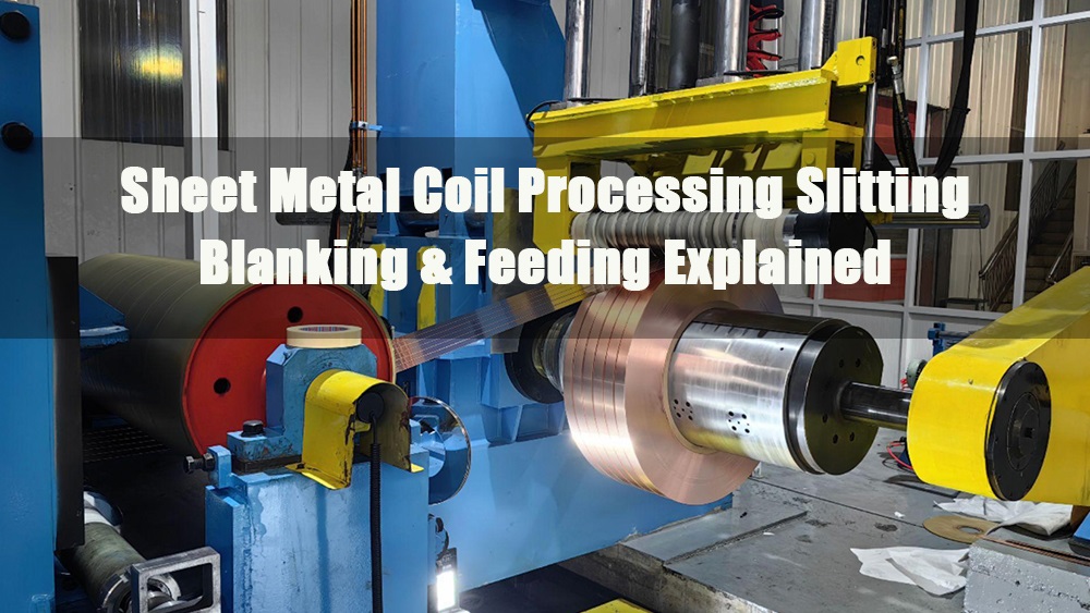
6.0Benefits of Coil Processing
High-volume stamping operations increasingly rely on coil stock feeding to maximize productivity. Modern coil feeding systems offer continuous material delivery, reduce manual handling, and minimize floor space and labor requirements, making them ideal for automated press lines.
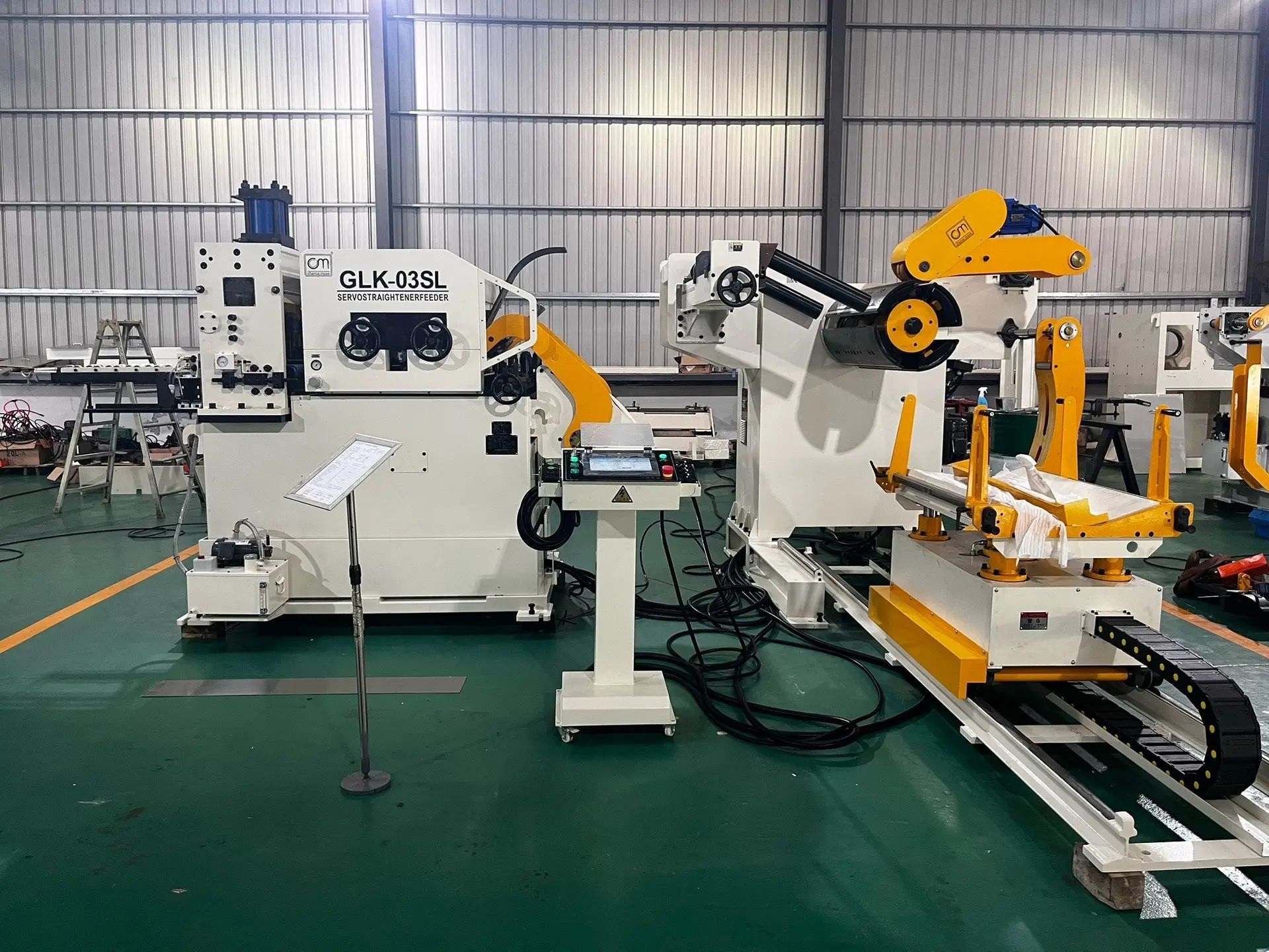
A particularly efficient solution is the 3-in-1 Decoiler Straightener and Feeder System, which integrates uncoiling, straightening, and feeding into a single compact unit. This design simplifies line setup, shortens coil changeover time, and ensures synchronized operation with the stamping press.
6.1Coil Processing Line Functions
A complete coil processing system typically includes:
- Uncoiling sheet metal from rolls
- Straightening/leveling to remove coil-set curvature
- Feeding into the press
- Scrap processing for waste management
To perform these functions, various equipment configurations are used:
- Pay-off reels support and uncoil the metal coil.
- Coil cradles are suited for handling thicker or less finish-sensitive materials.
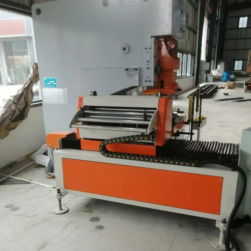
- Straighteners or levelers use adjustable rollers to eliminate curvature, ensuring flat sheet entry into the die.
In many advanced stamping lines, a 3-in-1 Decoiler Straightener and Feeder replaces separate machines, offering a space-saving and fully synchronized solution. These all-in-one systems improve feeding accuracy and reduce misalignment, especially beneficial in high-speed or precision applications.
Equipment Details:
- Pay off the reel support and uncoil the metal.
- Coil cradles are used for thicker or non-finish-sensitive materials.
- Straighteners or levelers correct curvature via adjustable rollers, ensuring flat material enters the die.
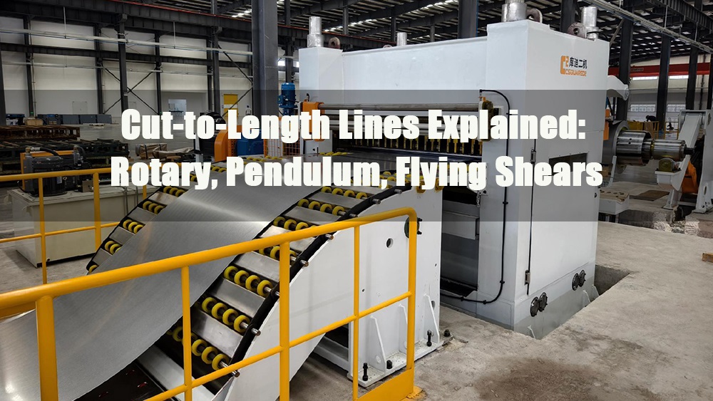
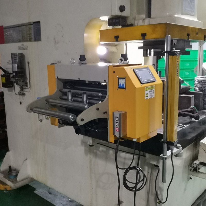
7.0Press Feeding Mechanisms
Automated feeding systems reduce labor and increase efficiency. Types include:
7.1Slide Feeds
Grippers move the coil a set distance, release, and return for the next cycle.
7.2Roll Feeds
- Most common system.
- Intermittently driven opposed rollers feed material.
- Allows the coil to dwell during the press stroke.
- Often powered pneumatically or hydraulically.
7.3Servo Feeds (Digitally Controlled)
Independently powered rollers allow:
- Joggle feeding
- Zig-zag patterns
- Oscillating feeds
- Shuttle feeds
Servo-driven systems provide precise control, increase strokes per minute, and reduce scrap.
8.0Scrap Processing
All coil-fed stamping lines generate some scrap. This can be managed in two ways:
- Integrated scrap ejection via the stamping die
- External scrap systems, either press-actuated or independently powered
9.0Applications of Stamping Presses Across Industries
Stamping presses are indispensable across a wide range of industries due to their versatility, speed, and ability to produce high-precision parts at scale.
- Automotive Industry: Perhaps the largest consumer of stamping technology, the automotive sector uses presses to manufacture body panels, brackets, reinforcements, and chassis components. High-speed mechanical presses are commonly used for producing parts with consistent geometry and finish.
- Appliance Manufacturing: In the home appliance sector, stamping presses produce enclosures, control panels, support frames, and inner assemblies for refrigerators, ovens, washing machines, and more. The ability to handle large sheet formats is critical in this application.
- Electronics and Electrical Components: Precision stamping presses form terminals, connectors, shielding components, and contact plates used in circuit boards and assemblies. High-speed presses are favored for their ability to produce small, delicate parts in high volumes.
- Aerospace and Defense: Aircraft components, structural reinforcements, and custom brackets are often formed with straight-side or hydraulic presses that offer higher precision and force across longer strokes.
- Construction and HVAC: Stamping presses form ductwork components, brackets, panels, and architectural profiles. Automated feeding lines ensure consistent output in these industries with varying material thicknesses.
10.0Conclusion
Stamping presses are diverse, high-performance machines essential to modern manufacturing. Choosing between mechanical and hydraulic systems, selecting the right frame type, and implementing advanced coil feeding systems all play critical roles in productivity and part quality. As automation and digital controls evolve, so too will press capabilities—ushering in faster, more flexible, and more cost-efficient stamping processes across industries.
11.0Frequently Asked Questions (FAQ)
What is the difference between a mechanical and hydraulic press?
Mechanical presses are faster and ideal for high-speed stamping, while hydraulic presses offer full force throughout the stroke and are better suited for deep drawing and complex shapes.
How do I choose between a C-frame and a straight-side press?
C-frame presses are more compact and economical but may suffer from deflection under heavy loads. Straight-side presses offer improved accuracy and enhanced support for large or high-force operations.
What materials can stamping presses work with?
Common materials include mild steel, stainless steel, aluminum, copper, and coated metals. Material thickness, tensile strength, and forming characteristics should be matched with the appropriate press type.
Why is coil feeding preferred over manual feeding?
Coil feeding ensures uninterrupted production, reduces handling time, improves safety, and enables higher speeds, especially important in large-volume operations.
Can presses be automated?
Yes, most modern stamping presses can be fully automated with servo feeds, robotic part handlers, die changers, and CNC-based press controllers.
References
https://pavithrasprings.com/press-components.html
https://www.iqsdirectory.com/articles/hydraulic-press.html