- 1.0Process Analysis: The Single Point Cutting Tool Model
- 2.0Geometry of the Single Point Tool
- 3.0Tool Life, Tool Wear, and Surface Finish
- 3.1High-Stress Cutting Conditions and Wear Mechanisms
- 3.2Types of Tool Wear: Crater and Flank
- 3.3Tool Life Criteria
- 3.4Taylor’s Tool Life Equation
- 3.5Built-Up Edge (BUE)
- 3.6Tool Wear vs. Feed and Cutting Speed
- 3.7Typical Cutting Tool Materials
- 3.8Surface Finish and Its Influencing Factors
- 3.9Additional Factors Affecting Surface Finish
In metal machining, the single-point cutting tool model serves as a foundational concept for understanding how cutting processes work. This model highlights the importance of tool geometry, cutting speed, and feed rate in determining machining efficiency and the quality of the finished product. By grasping these factors, manufacturers can better control chip formation, cutting forces, and ultimately reduce defects and costs.
Moreover, tool wear and failure mechanisms play a critical role in machining performance. Analyzing how different wear types—such as adhesion, abrasion, and diffusion—develop helps in predicting tool life and planning maintenance. Optimizing cutting parameters based on these insights leads to improved surface finish and longer tool usage, enhancing overall production economics.
1.0Process Analysis: The Single Point Cutting Tool Model
No matter what manufacturing process you use, there are various factors that work together and affect the quality, yield, and overall economics. For example, in die casting, parameters such as:
- The temperature of the molten metal.
- The rate of cooling induced in the dies using coolants,
- the surface finish of the die (which affects the flow rate of the metal),
- and the pressure at which the melt is pushed into the die all play an important role.
Depending on the settings of these parameters, the percentage of defective parts, the rate of production, and the dimensional variations in the parts will vary. Furthermore, operating conditions also influence power consumption. The size and design of the machine and dies — which need to withstand high pressure and temperature — also affect the cost.
Therefore, it is of great importance to be able to control the process effectively.
In most companies, a series of experimental runs is conducted until the “ideal” working conditions for producing each part are found. However, it is not sufficient to conduct such experiments without prior knowledge of the process behavior.
If we can anticipate the types of trends that will occur during experiments where certain parameters are varied, we can tremendously reduce operations planning time.
A good understanding of the relationship between the process output and its controlling parameters also helps us to use the process in a more optimized fashion. This deeper understanding of process behavior can be achieved by developing analytical models of the process.
The reason for this is that we already know how to find optimum values for analytical models—such as those represented by mathematical equations. For example, if the model is a real-valued continuous function, we can find its maximum (or minimum) using simple differential calculus.
Since we don’t have time to study such models for every process in detail, this course will focus on developing analytical models for a simple cutting process — specifically, the Single Point Cutting Tool Model.
2.0Geometry of the Single Point Tool
Understanding Cutting Angles, Tool Shape, and Chip Formation in Orthogonal Cutting
2.1The Orthogonal Cutting Model
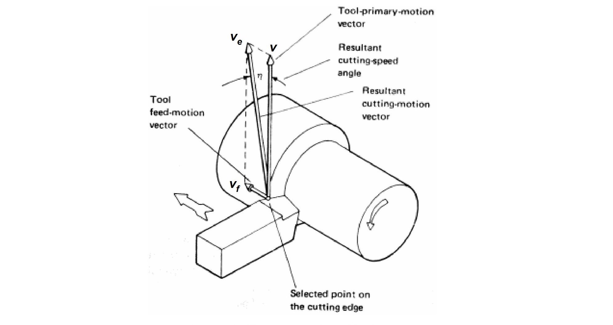
Probably the simplest model to analyze is the Single Point Tool, Orthogonal Cutting model. This model is most easily visualized through the turning process, where cutting is achieved by moving the tool relative to the rotating part.
To describe this motion, it is helpful to separate the relative velocity into two components:
-
Cutting speed: vv
-
Feed rate: vfv_f
In most practical scenarios, the feed rate vfv_f is much smaller than the cutting speed vv, so the effective cutting speed ve≈vv_e \approx v. For the purpose of this chapter, we will assume ve=vv_e = v unless otherwise stated.
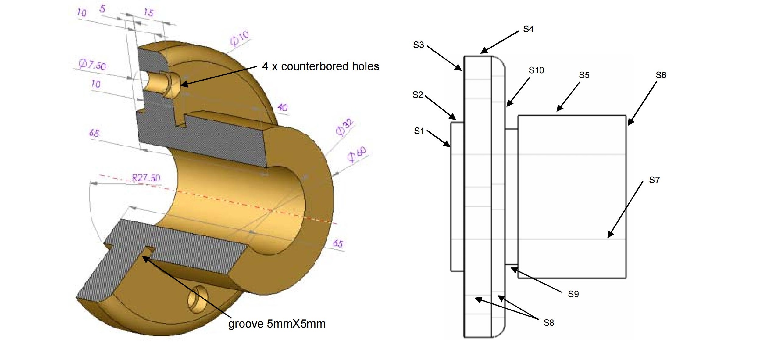
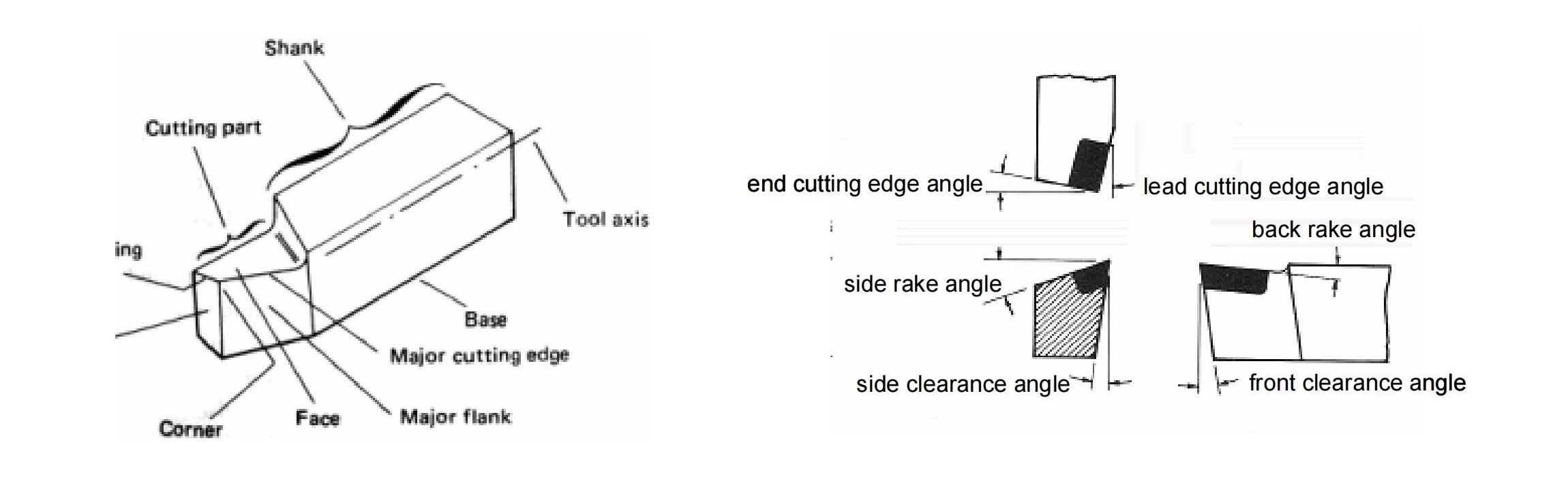
2.2Tool Geometry and Its Importance
The figure above illustrates that a cutting tool is not a simple rectangular block — each face is inclined at a specific angle. Understanding the geometry of the tool is essential for deeper analysis.
A simplified schematic of a tool (below) shows key aspects of this geometry:
- Rake angles: Define the ‘knife-edge’ of the cutter
- Clearance angles: Minimize friction between tool and workpiece
- Nose radius: Important for durability, as a perfectly sharp edge would wear or fracture rapidly
- Side rake angle: Will be discussed further in later sections
2.3Rethinking Chip Formation: Shear vs. Tension
In early theories of machining, it was believed that material is removed by tensile fracture — essentially, the tool was thought to “push apart” the material.
However, later micrograph studies revealed that most of the material deformation and chip formation occur due to shear failure, not tension. The figure below illustrates the evolution of this understanding.
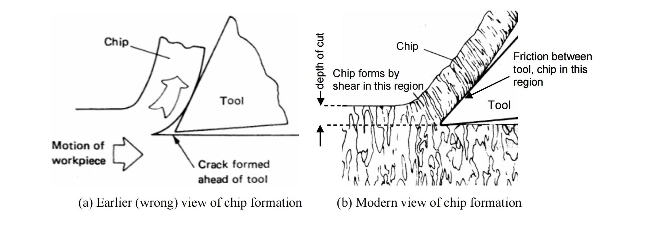
(a) Earlier (incorrect) view: tension fracture
(b) Modern view: shear failure
2.4Why Cutting Force Prediction Matters
Being able to predict cutting forces as a function of tool geometry, cutting speed, and workpiece material is crucial. This knowledge can help:
- Estimate the power rating needed for a machine tool
- Evaluate machinability of a material
- Plan for tool life and production rates
While several theoretical models have been proposed to relate cutting force to process parameters, they often simplify assumptions to the point of being less useful in practice.
Therefore, for more accurate and applicable analysis, experimental data remains the preferred method. For further reading and case studies, refer to Fundamentals of Metal Machining and Machine Tools by Geoffrey Boothroyd.
3.0Tool Life, Tool Wear, and Surface Finish
Understanding Wear Mechanisms, Tool Failure Criteria, and Their Impact on Machining Quality
3.1High-Stress Cutting Conditions and Wear Mechanisms
Cutting involves:
- High stresses
- High relative velocity between tool and chip/workpiece
- High temperatures (up to 1000°C)
These extreme conditions cause progressive damage to the tool, primarily due to three mechanisms:
- Adhesion wear:
Small fractured pieces of the workpiece may weld to the tool surface due to high temperatures. When they break off, they tear off small parts of the tool. - Abrasion:
Hard particles and microscopic variations on the chip’s underside constantly rub against the tool, gradually wearing it down. - Diffusion wear:
At elevated temperatures, atoms in the tool material diffuse into the chip. This weakens the tool’s microstructure and increases the likelihood of fracture. Diffusion rates increase exponentially with temperature.
3.2Types of Tool Wear: Crater and Flank
Over time, two measurable types of wear appear on a tool:
- Crater wear: A depression formed on the tool face. Measured by its maximum depth.
- Flank wear: Found along the flank of the tool. Measured by the average width of the worn zone.
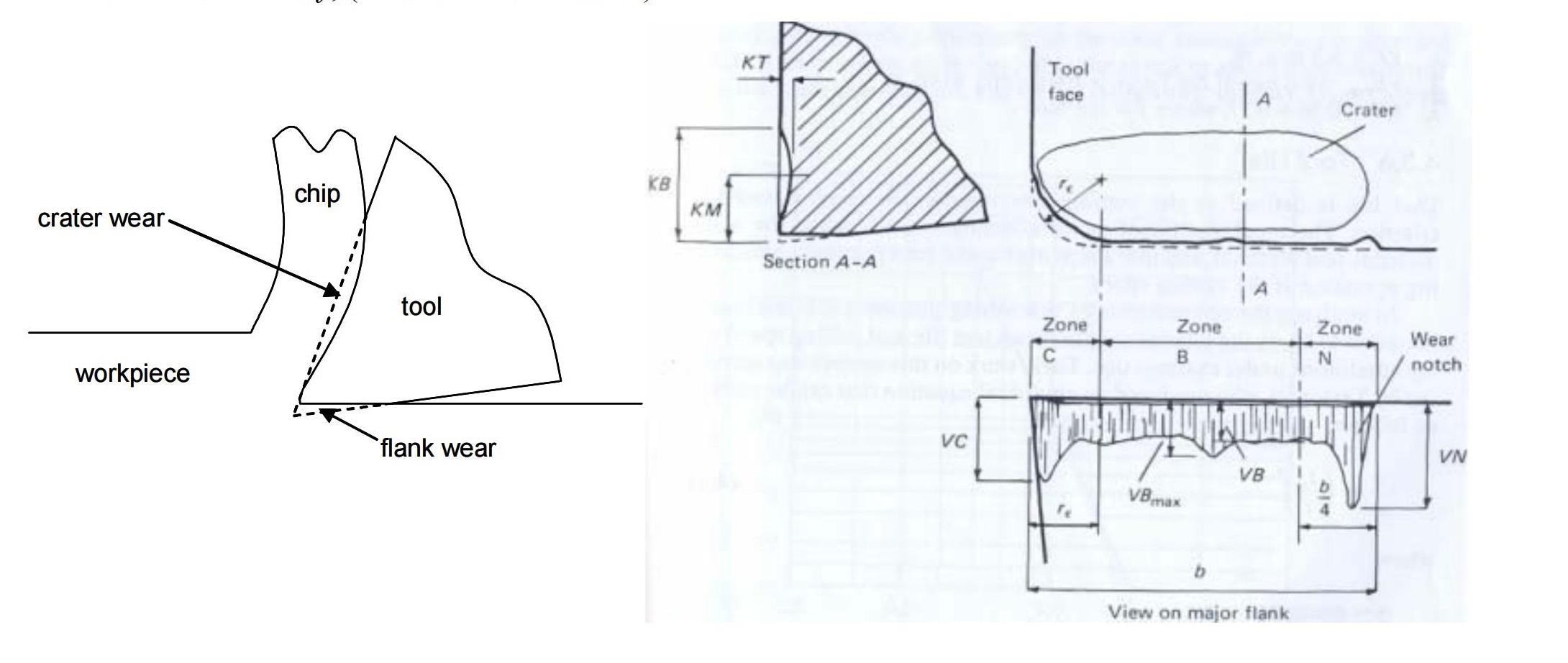
(b) Measurement of wear
Once wear exceeds a predefined limit, the tool is considered to have reached the end of its useful life. At that point, it is either discarded or reconditioned (e.g., edge re-sharpened by grinding).
3.3Tool Life Criteria
Common criteria for tool life termination (also known as tool-life criteria) include:
- Catastrophic failure – complete breakage of the tool
- Uniform flank wear – average wear width VB=0.3 mmVB = 0.3 \text{ mm}
- Non-uniform flank wear – max wear width VBmax=0.6 mmVB_{max} = 0.6 \text{ mm}
- Crater wear – KT=0.06+0.3fKT = 0.06 + 0.3f where ff is the feed in mm
3.4Taylor’s Tool Life Equation
In the early 1900s, F. W. Taylor demonstrated that the cutting speed VV is the most critical factor in determining tool life. He proposed the now-famous Taylor Tool Life Equation:
VTn=cVT^n = c
- VV: cutting speed
- TT: time until failure
- nn, cc: constants for a given tool-workpiece material pair
3.5Built-Up Edge (BUE)
During machining, a thin layer of the workpiece material may deposit onto the tool surface, becoming work-hardened under high stress. This can lead to multiple hardened layers accumulating—forming a Built-Up Edge (BUE).
BUE causes poor surface finish and alters tool geometry. However, BUE can be minimized by:
Decreasing depth of cut
Increasing rake angle
Using appropriate cutting fluids
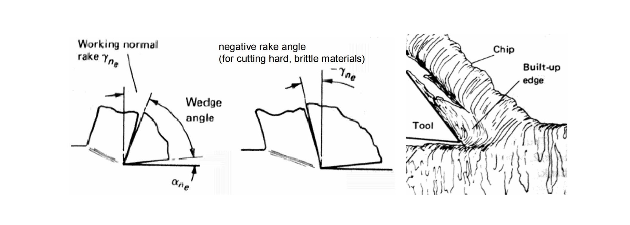
(b) Formation of Built-Up Edge
3.6Tool Wear vs. Feed and Cutting Speed
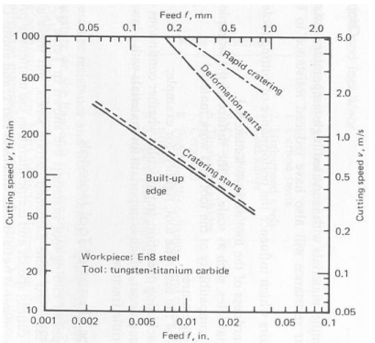
This experimental data helps determine the optimal cutting parameters for extending tool life and improving machining efficiency.
3.7Typical Cutting Tool Materials
To withstand harsh machining conditions, cutting tools must have:
- High hardness
- High impact strength
- Wear resistance at high temperatures
Common tool materials include:
- High-Speed Steel (HSS):
Alloy of iron with ~18% tungsten and ~4% chromium. - Cemented Carbides:
Sintered materials (~94% tungsten, ~6% carbon, <1% cobalt).
Modern tools often use steel shanks with replaceable inserts made of:
Carbide
Coated carbide (with coatings such as tungsten carbide, titanium carbide, titanium nitride, cubic boron nitride (CBN), or even diamond)
Coating thickness typically ranges from 5–8 microns.
3.8Surface Finish and Its Influencing Factors
Cutting parameters—speed, feed, and depth of cut—directly affect both tool life and surface finish, which in turn impact the economics of machining.

(b) Surface roughness RmaxR_{max}Rmax as a function of feed and tool geometry
3.9Additional Factors Affecting Surface Finish
Besides feed and geometry, surface quality is also influenced by:
- Machine tool vibrations
- Inaccuracies in table/motion systems
- Workpiece material properties
- Scratching by chips during cutting