Introduction
Sheet metal fabrication tolerances define the acceptable deviations in size, geometry, and other features of fabricated parts. These tolerances are essential for accurate installation, consistent assembly, and smooth integration with other components.
In most cases, manufacturers follow ISO 2768-mk to control:
- Linear and angular dimensions
- Flatness and straightness
- Cylindricity and circularity
The following sections summarize standard tolerances and key design tips for achieving precise and efficient sheet metal fabrication.
1.0Standard Tolerances for Sheet Metal Fabrication
1.1Metal Spinning Tolerances (ISO 2768 Standard Reference)
The table below shows permissible deviations (mm) according to ISO 2768, based on different nominal length ranges:
What Is ISO 2768? Complete Guide to Standard Tolerances
| Nominal Size Range (mm) | Fine (f) | Medium (m) | Coarse (c) | Very Coarse (v) |
| 0.5 up to 3 | ±0.1 | ±0.2 | — | — |
| Over 3 up to 6 | ±0.05 | ±0.1 | ±0.3 | ±0.5 |
| Over 30 up to 120 | ±0.1 | ±0.2 | ±0.5 | ±1.0 |
| Over 120 up to 400 | ±0.15 | ±0.3 | ±0.8 | ±1.5 |
| Over 400 up to 1000 | ±0.2 | ±0.5 | ±1.2 | ±2.5 |
| Over 1000 up to 2000 | ±0.3 | ±0.8 | ±2.0 | ±4.0 |
| Over 2000 up to 4000 | ±0.5 | ±1.2 | ±3.0 | ±6.0 |
1.2External Radius and Chamfer Heights
| Range (mm) | Fine (f) | Medium (m) | Coarse (c) | Very Coarse (v) |
| 0.5 to 3 | ±0.2 | ±0.2 | ±0.4 | ±0.4 |
| Over 3 to 6 | ±0.5 | ±0.5 | ±1.0 | ±1.0 |
| Over 6 | ±1.0 | ±1.0 | ±2.0 | ±2.0 |
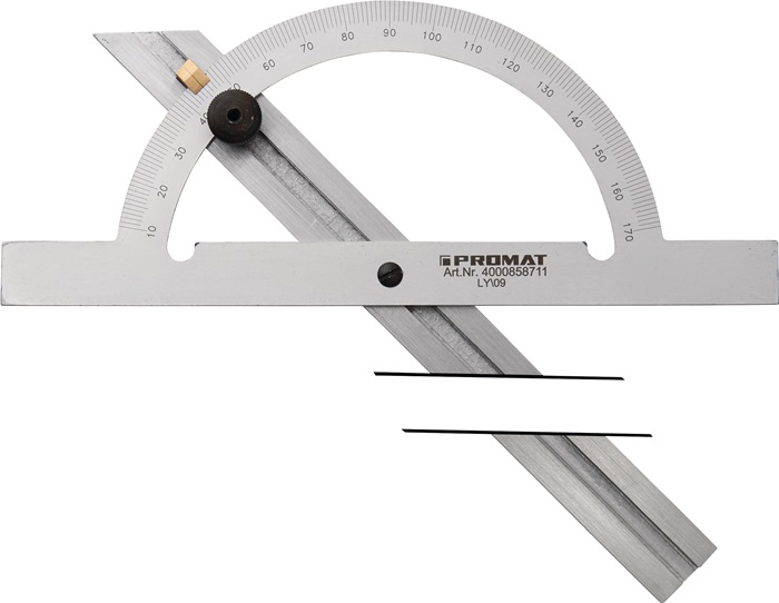
1.3Angular Dimension Tolerances
| Nominal Length (mm) | Fine (f) | Medium (m) | Coarse (c) | Very Coarse (v) |
| Up to 10 | ±1° | ±1° | ±1°30′ | ±2° |
| Over 10 to 50 | ±0°30′ | ±0°30′ | ±1° | ±2° |
| Over 50 to 120 | ±0°20′ | ±0°20′ | ±0°30′ | ±1° |
| Over 120 to 400 | ±0°10′ | ±0°10′ | ±0°15′ | ±0°30′ |
| Over 400 | ±0°05′ | ±0°05′ | ±0°10′ | ±0°20′ |
2.0Design Tips for Sheet Metal Fabrication
Optimizing your design helps reduce manufacturing costs and ensures high-quality results. Below are critical design guidelines based on standard DfM practices and industry analysis.
2.1Wall Thickness
Uniformity: Maintaining consistent wall thickness across the entire component is crucial for structural integrity and accurate assembly. Uneven thickness can lead to warping, misalignment, and tolerance issues during fabrication.
Recommended Thickness Ranges:
- General Fabrication: 9 – 20 mm (commonly for sheets under 3 mm, processed with Shearing Machines or Guillotine Shears).
- Laser Cutting:5 – 10 mm is ideal when using CNC Laser Cutting Machines, which provide high precision and minimal heat distortion.
- Bending: 5 – 6 mm is recommended for consistent results on Press Brake Machines or CNC Press Brakes, ensuring accurate bends without cracking or excessive springback.
2.2Bends
Bending is a critical process in sheet metal fabrication, directly affecting part accuracy and overall quality. Proper parameter selection ensures minimal material deformation and consistent tolerances. Most bending operations are performed on Press Brake Machines or CNC Press Brakes, which allow precise control over bend angles and dimensions.
2.3K-Factor
- Definition: The K-factor is the ratio between the neutral axis (t) and material thickness (Mt), expressed as K = t / Mt.
- Recommended Range: 3 – 0.5 (with an average of ~0.4468 for most metals).
- Purpose: Accurately calculating the K-factor helps determine bend allowance and flat patterns, preventing tearing and excessive material thinning. CNC Press Brake Machines with programmable bend allowance calculators can automatically adjust K-factor values for repeatable accuracy.
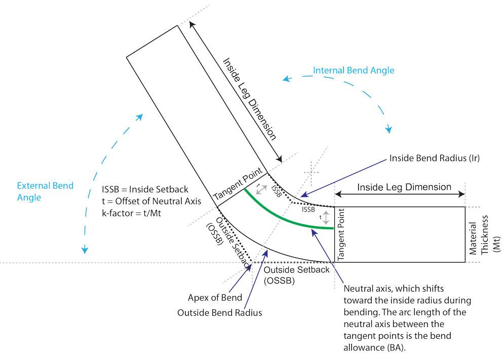
2.4Bend Radius
- Definition: The bend radius is the distance between the bend axis and the material’s internal surface.
- Guidelines:
- For ductile materials such as stainless steel, the interior bend radius should be at least equal to the material thickness to prevent cracking.
- For brittle metals (e.g., aluminum alloys), larger bend radii are recommended to reduce strain and distortion.
- Equipment Tip: Modern CNC Press Brakes with radius tooling are ideal for achieving consistent bend radii, even on complex components.
2.5Bend Orientation
Maintaining consistent bend orientation helps reduce the need for part re-orientation, which lowers production costs and shortens lead times. Automated Press Brake Machines with multi-axis back gauges can further minimize manual adjustments, ensuring uniform bend direction throughout production.
2.6Bend Relief
Adding bend relief is essential to prevent tearing or deformation near edges.
- Depth: Greater than the bend radius.
- Width: At least equal to the material thickness.
- Benefits: Bend relief improves stiffness and minimizes springback, especially on high-strength steel processed with Hydraulic Press Brakes or CNC Servo-Electric Press Brakes.
2.7Bend Height
- Minimum Height: At least 2 × material thickness + bend radius.
- Reason: Too-small bend heights make it difficult to position the sheet accurately in press brakes, which may result in poor bend quality or deformation. CNC Press Brakes with precise clamping systems are recommended for forming small bend heights while maintaining tight tolerances.
2.8Hems
Hems are used to eliminate sharp edges, enhance safety, and add structural strength to sheet metal components.
- Consistency: Follow the same bend orientation guidelines to reduce unnecessary part re-orientation, improving efficiency on Press Brake Machines.
- Bend Height: Should meet the general bend height recommendation (≥2 × material thickness + bend radius).
2.9Hole Size and Spacing
Guidelines
- Diameter: ≥ material thickness (preferably larger to reduce tooling wear and costs).
- Spacing: ≥ 2 × sheet metal thickness.
- Edge Distance: ≥ material thickness to avoid tearing.
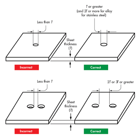
Summary Table
| Design Feature | Recommended Value |
| Minimum Hole Diameter | ≥ Material thickness |
| Hole Spacing | ≥ 2 × Material thickness |
| Distance from Edge | ≥ Material thickness |
2.10Curls and Countersinks
Curls
- Outside Radius: ≥ 2 × material thickness.
- Hole Size Near Curls: ≥ curl radius + material thickness
Countersinks
- Depth: ≤ 0.6 × material thickness.
- Distance Between Centers: ≥ 8 × material thickness.
- Distance from Bend Line: ≥ 3 × material thickness.
2.11Tabs and Notches
Tabs
- Length: ≤ 5 × width.
- Width: ≥ 2 × material thickness.
Notches
- Width: ≥ material thickness.
- Spacing: ≥ 1/8 inch between notches.
- Proximity to Bends: ≥ 3 × metal thickness + bend radius.
2.12Sheet Metal Gauge Considerations
- Thicker Sheets: May limit achievable bend angles and cause micro-cracks.
- Recommended Practice: Use thinner, more pliable metals unless high structural strength is required.
3.0Materials for Sheet Metal Fabrication
Choosing the right material depends on application, strength, corrosion resistance, and machinability. Below are common options:
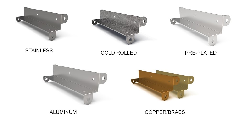
3.1Stainless Steel
Properties: Corrosion resistance, high durability, temperature resistance, good formability.
Applications:
- Cooking utensils
- Aerospace and automotive parts
- Food processing equipment
- Chemical and fuel containers
3.2Hot Rolled Steel
Properties: Flexible, malleable, less strict dimensional tolerance.
Applications:
- Vehicle frames
- Agricultural equipment
- Rail tracks and car components
3.3Cold Rolled Steel
Properties: ~20% stronger than hot rolled, smooth finish.
Applications:
- Automotive parts
- Home appliances
- Lighting fixtures
3.4Copper and Brass
- Copper: Malleable, corrosion-resistant, easy to shape.
- Brass: Corrosion-resistant, high electrical conductivity, high-temperature resistance.
- Applications: Fixtures, electronic equipment, kitchen utensils.
3.5Pre-Plated Steel
- Properties: Pre-Plated Steel, often processed using Decoiler and Straightener Feeder Lines, ensures smooth feeding for stamping and bending operations
- Applications: Equipment bodies, enclosures.
3.6Aluminum
Properties: Lightweight, strong, corrosion-resistant, good thermal and electrical conductivity.
Applications:
- Automotive and aircraft parts
- Electrical enclosures
- Food packaging
4.0Surface Finishing Options for Sheet Metal
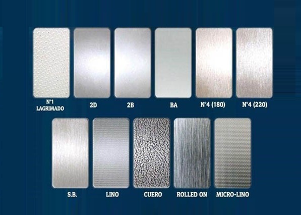
4.1Bead Blasting
- Process: Abrasive particles (sand or glass beads) are blasted with compressed air.
- Pros: Smooth matte texture, eco-friendly, suitable for sensitive surfaces.
- Cons: Not fast, not ideal for small projects.
4.2Powder Coating
- Process: Powdered paint is sprayed and baked to form a protective layer.
- Pros: Excellent corrosion resistance, long-lasting, economical.
- Cons: Limited color mixing, may be expensive for small runs.
4.3Anodizing
- Types:
- Type I: Thin layer, chromic acid
- Type II: Sulfuric acid, corrosion-resistant
- Type III: Hard-coat, wear-resistant
- Pros: UV-stable, durable finish
- Cons: Limited to specific metals
4.4Brushing
- Process: Filamentary brushes remove burrs and improve surface smoothness.
- Pros: Improves durability and corrosion resistance
- Cons: Susceptible to damage, brush marks may remain
4.5Screen Printing
- Use: Logos, labels, safety instructions
- Pros: Cost-effective, no color size restrictions
- Cons: Precision color matching is difficult
4.6Why Tolerance Control Matters in Sheet Metal Fabrication
Maintaining tight tolerances ensures:
- Accurate assembly and installation
- Reduced material waste and rework
- Improved durability and performance
- Lower production costs and faster lead times
5.0Conclusion
Understanding and applying proper sheet metal fabrication tolerances is critical for ensuring high-quality parts, cost efficiency, and fast production cycles. Following ISO 2768 standards and incorporating design-for-manufacturing (DfM) principles—such as maintaining uniform wall thickness, correct bend radii, and proper hole spacing—reduces rework, improves assembly accuracy, and extends product lifespan.
When combined with the right material selection and surface finishing options, these practices help manufacturers achieve consistent results across industries such as automotive, aerospace, electronics, and industrial machinery.
6.0Frequently Asked Questions (FAQ)
What is the standard tolerance for sheet metal fabrication?
Most manufacturers follow ISO 2768-mk, with linear dimension tolerances ranging from ±0.05 mm for small parts to ±6.0 mm for very large components.
What is the recommended K-factor for sheet metal bending?
The K-factor typically ranges from 0.3 to 0.5, with an average of 0.4468 for most bending operations.
How does wall thickness affect sheet metal fabrication?
Thicker sheets improve structural strength but may limit achievable bend angles and increase the risk of cracking. Thinner sheets are easier to form and bend but may reduce structural rigidity.
Which materials are best for corrosion resistance?
Stainless steel, aluminum, copper, and brass offer excellent corrosion resistance. Stainless steel is commonly used in food, medical, and chemical industries.
What surface finishing is best for outdoor applications?
Powder coating and anodizing are ideal for outdoor use due to their high resistance to corrosion, UV, and weathering.