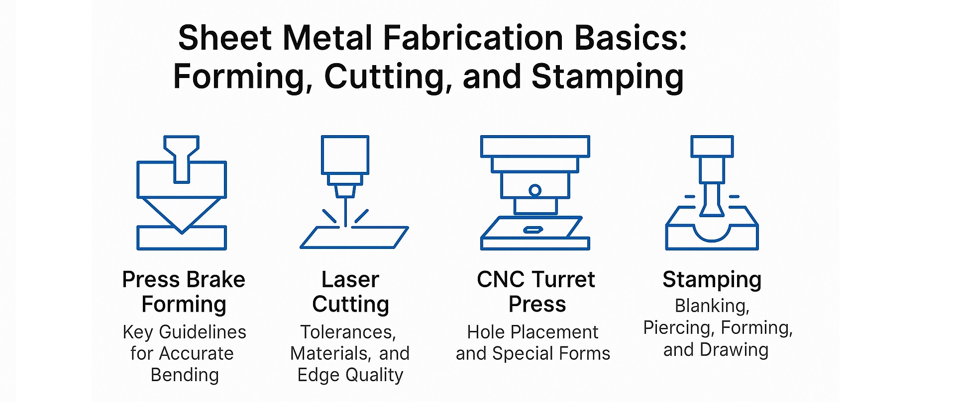
Sheet metal fabrication involves a range of forming and cutting processes, each with specific design considerations to ensure quality, efficiency, and cost-effectiveness. This guide focuses on essential forming guidelines for Press Brake Forming, as well as cutting principles for Laser Cutting Machines and CNC Turret Presses.
1.0Forming Basics: Press Brake Forming Guidelines
1.1Key Design Guidelines for Press Brake Forming
- Dimensioning Strategy: Dimension the part in a single direction wherever possible. Because press brake forming is a sequential bending process, each bend introduces slight dimensional variation. Single-direction dimensioning aligns with the process flow and helps control tolerance accumulation.
- Bend Tolerances: A bend tolerance of +/–0.007 in.is recommended. While tighter tolerances are achievable, they significantly increase production costs.
- Consistent Bend Radius: Use the same bend radius for all bends on a part whenever possible. This reduces setup changes. Radii specified in fractional inches are preferred, as press brake tooling is sized accordingly.
- Feature-to-Edge Dimensioning: Dimension from a feature to an edge rather than feature-to-feature across multiple planes. Feature-to-bend dimensions may require special gauging or fixtures, increasing costs.
- Critical Dimensions: Only truly critical dimensions should be specified as such. Unnecessary tight tolerances can lead to excessive manufacturing costs.
- Outside vs. Inside Dimensions: Unless the inside dimension is critical, always use the outside dimension for forming accuracy.
1.2Critical Forming Considerations in Sheet Metal Design
Critical Dimensions in Sheet Metal Forming: Use outside dimensions as the primary reference for measurement unless the inside dimension is functionally critical. This approach simplifies inspection, reduces tolerance stack-up, and minimizes unnecessary manufacturing costs.
1.3Embosses and Offsets
Emboss and offset dimensions should reference the same side of the material unless the overall height is critical. Over-specifying can increase part cost unnecessarily.
1.4Bend Radius Recommendations
As a rule, the inside bend radius should equal the material thickness. A smaller radius can cause material flow issues in softer metals and cracking in harder materials.
1.5Bend Relief
When forming near an edge, bend relief prevents tearing.
- The distance from the edge to the bend should be at least equal to the bend radius.
- Relief depth should exceed the bend radius, and relief width should be at least equal to the material thickness, preferably thickness + 1/64 in.
1.6Forming Near Holes
To avoid hole deformation during bending, follow these guidelines:
- Holes <1 in diameter: Minimum distance D = 2T + R
- Holes >1 in diameter or slots: Minimum distance D = 2.5T + R
(T = Material Thickness, R = Bend Radius)
1.7Form Height to Thickness Ratio
The minimum form height (D) for sheet metal: D = 2.5T + R. Lower heights are possible but often require costly secondary operations.
1.8Edge Distortion
Edge overhang caused by distortion can be as large as ½ the material thickness. For thicker metals or tighter radii, edge relief can prevent unacceptable overhang.
2.0Laser Cutting Basics
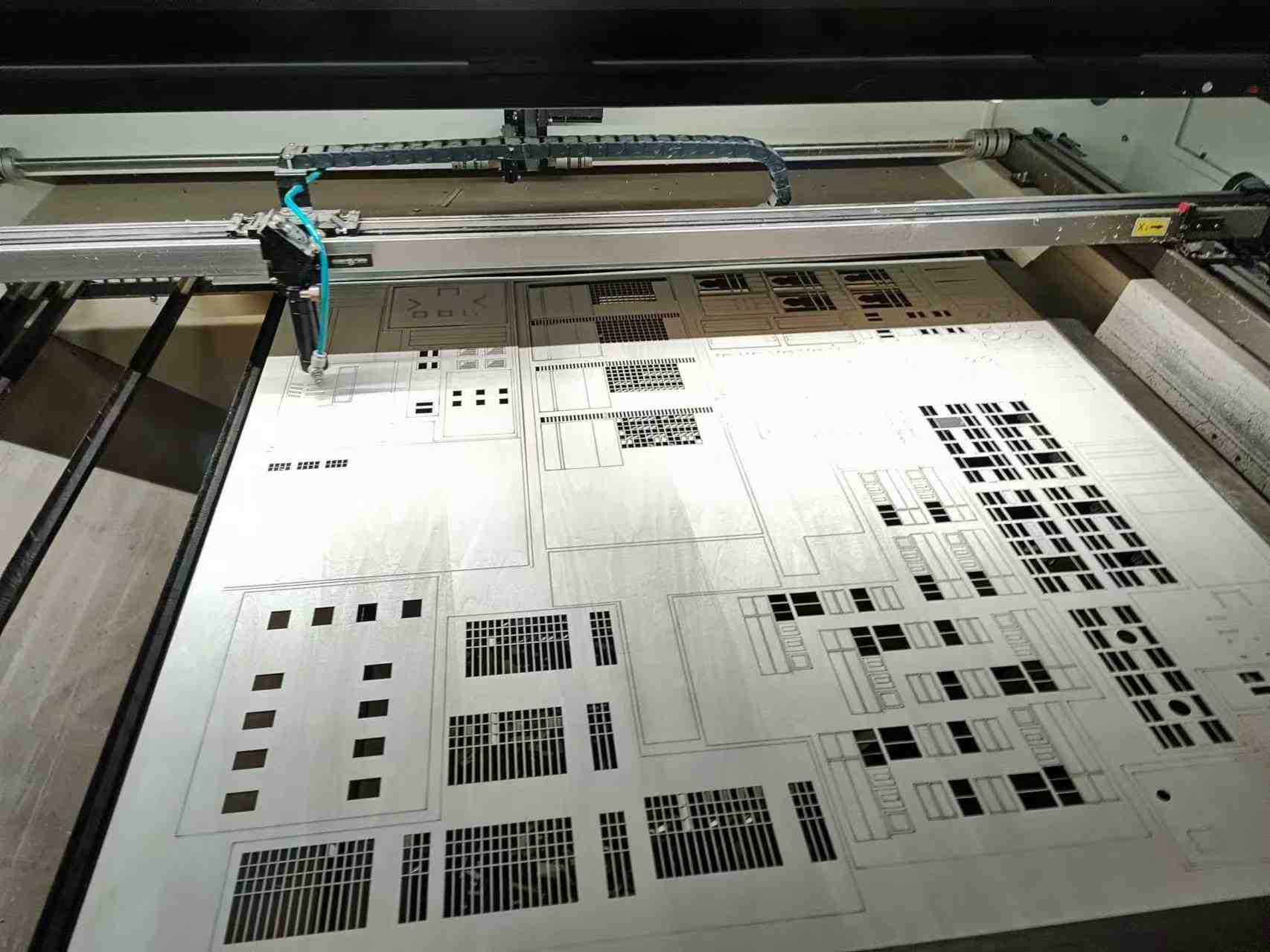
2.1Tolerances and Cutting Limits
- Standard feature-to-feature tolerance: +/–0.004 in.
- Minimum cut width: 008 in., determined by beam width.
2.2Material Restrictions
Three main factors—reflectivity, thickness, and flammability—limit laser cutting:
- Maximum Thickness: Metals up to 3/8 in.can be cut, though edge quality declines with thickness.
- Reflectivity: Highly reflective metals like copper or silver scatter the beam, making them unsuitable.
- Flammability: Heat-sensitive or flammable materials should be tested before cutting.
2.3Acceptable Materials
- Steel (Stainless, CRS, HRS)
- Aluminum (may require deburring)
- Galvanized and Galvaneal steel
- Plastic and Cardstock (subject to heat and flammability testing)
2.4Unacceptable Materials
- Copper and precious metals (high reflectivity)
- Paper stock (unless treated with flame retardant)
2.5Heat Affected Zone (HAZ)
Laser cutting introduces localized hardening along edges, which may affect secondary operations like tapping or reaming, especially on thicker metals.
2.6Hole Diameter Considerations
Laser-cut holes are slightly tapered (entry > exit diameter). Minimum hole size can be as small as 20% of stock thickness.
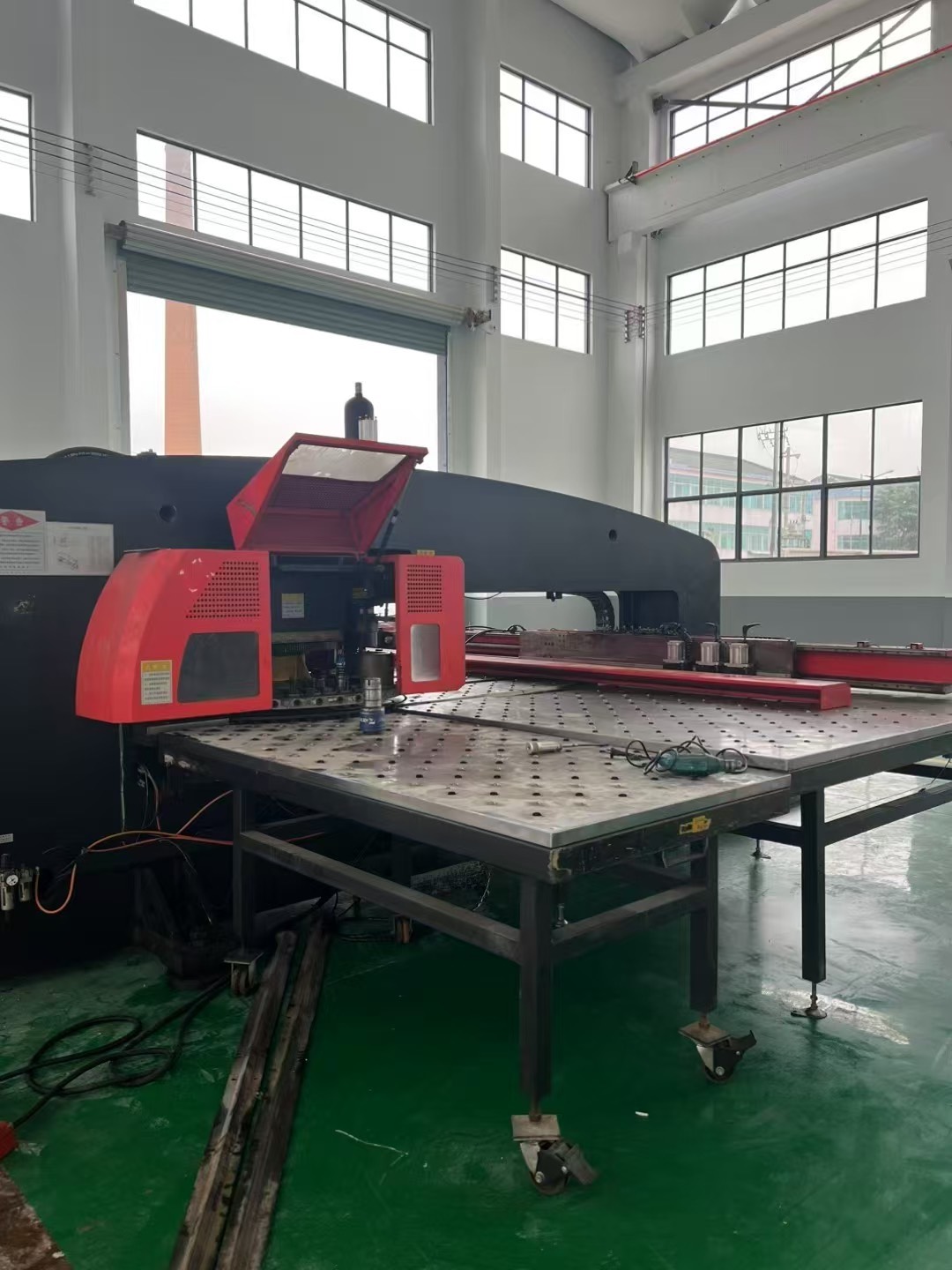
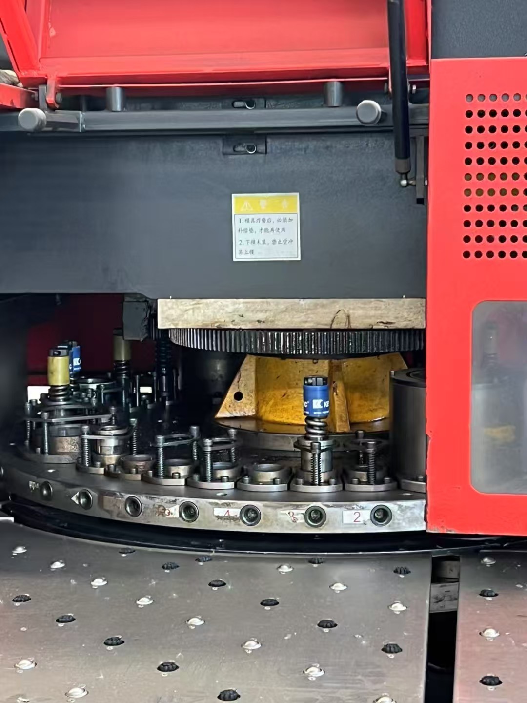
3.0CNC Turret Press Basics
The CNC Turret Press is highly efficient for low- to medium-volume runs, prototypes, and cost-effective production using standard “soft tooling.”
3.1Tolerances and Dimensioning
- Feature-to-feature tolerance: +/–0.004 in.
- Punched hole tolerance: +/–0.002 in.
- Use meaningful datum points (e.g., hole centers) rather than edges, which may be tapered or misaligned.
3.2Special Forms
Turret presses can produce various features, including countersinks, embosses, offsets, card guides, half-shears, and weld projections. Form depth must be <5/16 in. and fit within a 3.5 in. diameter circle.
3.3Hole-to-Edge Clearance
Keep holes at least one material thickness away from edges to avoid bulging. For fastening holes, allow extra web thickness to withstand added stress.
3.4Hole Diameter to Thickness Ratio
Hole diameter should not be less than material thickness. Higher tensile materials require larger punch diameters.
3.5Feature Placement
Maintain clearance between adjacent formed features to avoid flattening during punching. Progressive tools can handle small parts efficiently with lower initial tooling costs.
3.6Nibbling Large Radii
Large radii are formed by multiple hits with a flat tool, resulting in a scalloped edge that can be smoothed with deburring.
3.7Countersinks
Countersinks can be formed, punched, or machined, depending on material thickness and tolerance requirements:
- Formed: Low cost, for thin gauges (≤18 gauge).
- Punched: Common for gauges thicker than 18.
- Punched + Machined: For hard or heavy gauge metals.
- Machined Complete: High-cost, used only for high-precision or thick materials.
4.0Stamping Basics: Essential Guidelines for Precision Sheet Metal Stamping
4.1Blanking: Dimensional Accuracy and Edge Quality
Blanking is the process of cutting flat shapes from sheet metal using punches and dies. Dimensional accuracy is typically checked at the shear area or “cut band” on the punch side, as breakout on the die side can reduce precision.
For general blanking and shearing operations, Hydraulic Ironworker Machines and Multi-functional Combined Punching and Shearing Ironworker Machines are widely used in small- to medium-volume production because they combine punching, shearing, and notching functions in a single setup.
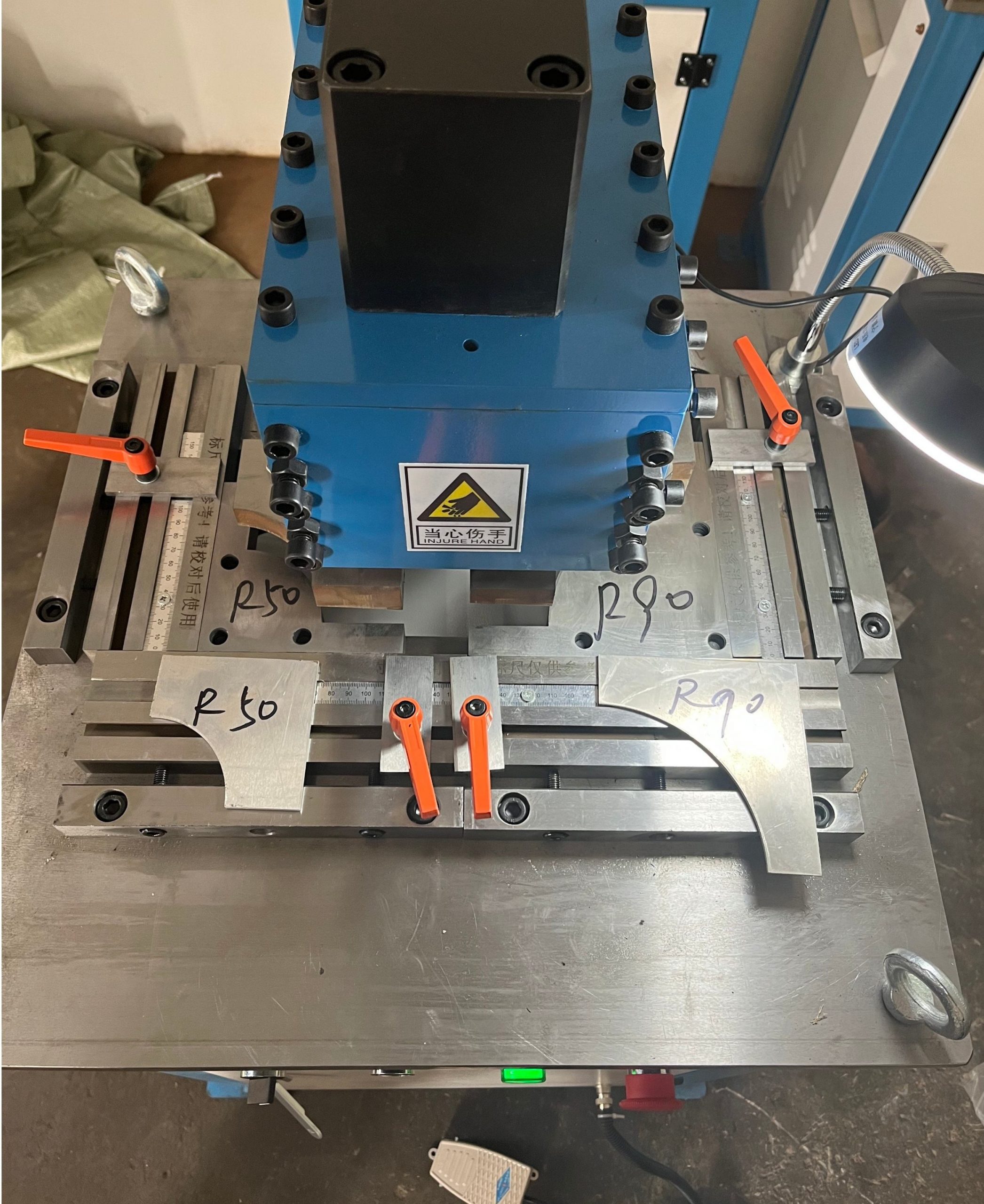
4.2Corners
Sharp corners are possible but increase tooling wear and cost. To extend tool life, specify corner radii equal to ½ material thickness or at least 0.015 in. For precise corner finishing, especially in thick gauge sheet metal, Sheet Metal Corner Notchers are often used to achieve clean and burr-free corners.
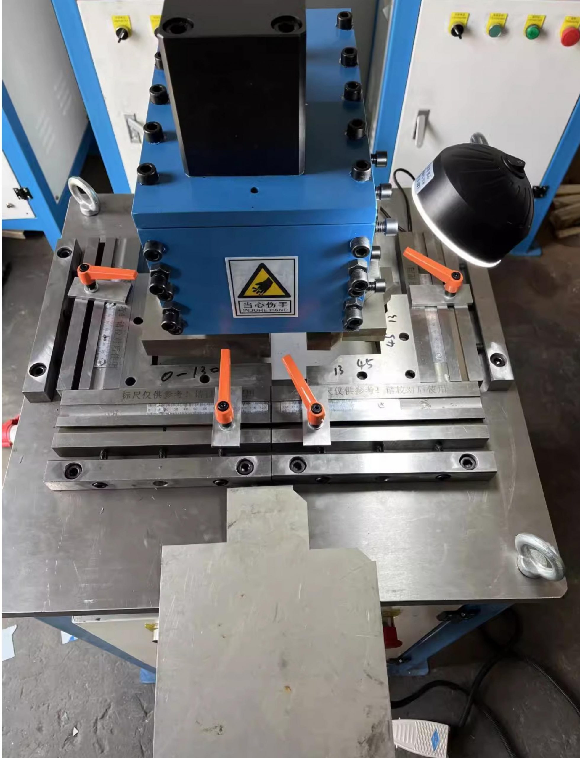
4.3Notches and Tabs
- Minimum notch or tab width: 5× material thickness
- Maximum notch length: 5× material thickness
4.4Cutoffs
Three common cutoff types are used in blanking:
- Straight/Square Cutoff: Most economical
- Half-Round or Partial Radius Cutoff: Moderate cost
- Full Radius Cutoff: Not recommended, as it leaves an unavoidable “feather-edge” burr
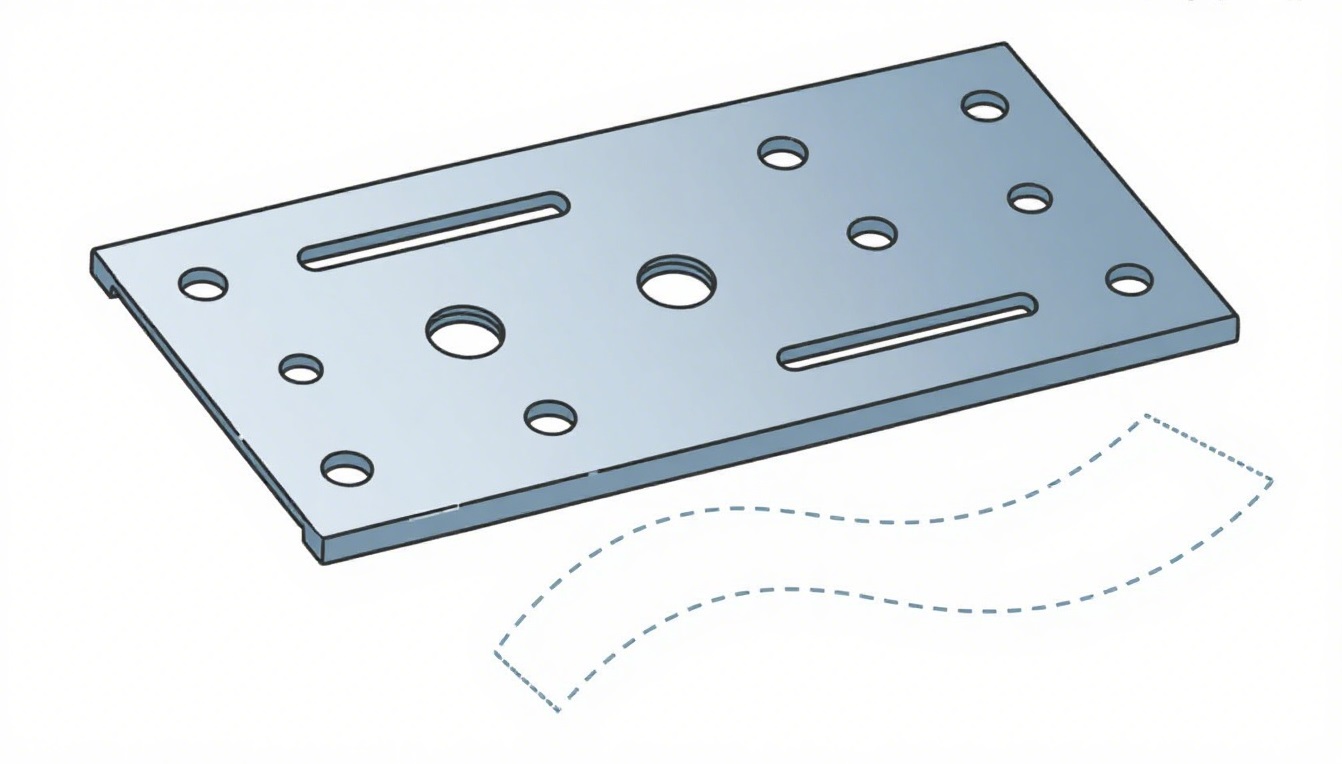
4.5Piercing: Hole and Edge Design
Piercing creates holes in sheet metal using punches and dies.
- Hole Diameter: Minimum size should be ≥1.2× material thicknessfor mild steel and ≥2× thickness for stainless steel or high-tensile alloys.
- Edge-to-Hole Distance: Maintain at least 2× material thickness(web width) to prevent bulging.
For precise punching in thicker materials, Hydraulic Ironworker Machines are often preferred due to their stable punching force and ability to handle multiple operations in a single stroke.
4.6Forming: Bend Relief and Hole Placement
Forming in stamping follows similar principles to CNC press brake forming.
- Bend Relief: Provide relief along L-shaped features to prevent tearing. Recommended: Width = 2T, Depth = T + R(T = Thickness, R = Bend Radius).
- Edge Bulging: Tight V-bend tolerances can cause bulging; bend relief minimizes this issue.
- Hole-to-Form Distance: Place holes at least 5T + Raway from the bend to avoid distortion.
- Slot-to-Form Distance: Long slots should be at least 4T + Rfrom the bend.
For complex formed edges, Sheet Metal Corner Notchers are commonly used to remove excess material before bending, reducing stress at the corners and improving forming accuracy.
4.7Drawing: Shapes and Radii
Drawing is used to form deep or complex 3D shapes, such as housings, enclosures, and structural components.
- Preferred Shapes: Round shapes are the easiest and most economical to draw. Squares are acceptable with generous corner radii, while irregular or combined shapes increase tooling cost.
- Radii Recommendations:
- Punch and die radius: ≥4× material thickness
- Part radius: ≥6× material thickness(with drawing-quality material)
Deep drawing is typically performed on mechanical stamping presses or hydraulic deep-draw presses for better control over forming forces.
5.0Conclusion
Optimizing metal stamping design requires balancing precision, cost, and manufacturability. By following these guidelines and selecting appropriate equipment—such as Hydraulic Ironworker Machines for multi-functional punching and shearing, Multi-functional Combined Punching and Shearing Ironworker Machines for versatile blanking operations, and Sheet Metal Corner Notchers for accurate and clean corner finishing—manufacturers can achieve high-quality stamped parts with reduced production costs.
6.0FAQ: Sheet Metal Forming, Cutting, and Stamping
Q1: What is the best bend radius for sheet metal forming?
A: The recommended inside bend radius should be equal to the material thickness. Using a smaller radius may cause cracking in hard metals or excessive stretching in soft metals.
Q2: Can laser cutting be used for all types of metals?
A: No. Highly reflective metals such as copper, silver, and some precious metals are not suitable for laser cutting because they scatter the beam. Thick metals above 3/8 in. can be cut, but edge quality decreases.
Q3: What is the minimum distance between a hole and a bend in sheet metal?
A: For holes less than 1 in. in diameter, the minimum distance (D) should be 2T + R. For larger holes or slots, D should be 2.5T + R, where T = material thickness and R = bend radius.
Q4: Why are Sheet Metal Corner Notchers used in stamping?
A: Sheet Metal Corner Notchers are used to achieve clean, burr-free corners and to remove excess material before forming. This reduces stress concentration at the corners and improves bending accuracy.
Q5: Which machines are best for small-batch sheet metal fabrication?
A: For small to medium production runs, Hydraulic Ironworker Machines and Multi-functional Combined Punching and Shearing Ironworker Machines are ideal because they combine punching, shearing, and notching in a single setup.
Q6: What is the difference between CNC Turret Press punching and laser cutting?
A: CNC Turret Press punching is faster for repetitive shapes and can create special forms like embosses or lances, but it leaves slight tapers on hole edges. Laser cutting provides smoother edges and is better for complex contours but has limitations on reflective materials.