- 1.0What Is Sheet Metal Bending?
- 2.0The Fundamentals of Metal Bending
- 3.0Key Design Considerations for Sheet Metal Bending
- 4.0Main Types of Metal Bending
- 5.0Key Terminology and Geometrical Parameters in Bending
- 6.0Key Bending Terms and Geometric Parameters
- 7.0Ductility Comparison of Common Metals and Bending Recommendations
- 8.0Common Challenges in Metal Bending and Solutions
- 9.0Types of Sheet Metal Bending Machines
- 10.0Advantages of CNC Sheet Metal Bending
- 11.0Comparison of Sheet Metal Bending and Other Manufacturing Processes
- 12.0Suitable Manufacturing Scenarios for Sheet Metal Bending
- 13.0Frequently Asked Questions (FAQ)
- 14.0Sheet Metal Bending Process Guide PDF
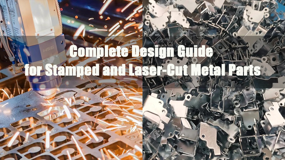
1.0What Is Sheet Metal Bending?
Sheet metal bending is a manufacturing process in which an external force is applied to a metal sheet, causing it to undergo plastic deformation at a specific location and form a desired angle, typically a V- or U-shape.
The process is also referred to as forming, hemming, folding, flanging, or die-bending. “Die bending” specifically involves using a punch and die set, while “bending” often refers to operations performed on a press brake.
The Role of Bending in Product Development
Sheet metal bending offers engineers, product designers, and manufacturers significant flexibility in creating complex geometries from a single metal piece, often without the need for secondary assembly. This approach offers several key advantages:
- Reduces the need for welding and mechanical fasteners
- Enhances structural strength and part consistency
- Lowers assembly costs and manual labor
- Simplifies manufacturing by minimizing the use of complex tooling
Bending is commonly combined with other processes such as laser cutting to create an efficient solution for low- to medium-volume production. It is especially suitable for applications that demand fast turnaround and design iteration across multiple product variants.
2.0The Fundamentals of Metal Bending
Metal bending is a forming process in which force is applied along a straight axis to plastically deform a flat sheet into a specific angle or shape. It’s a widely used method in sheet metal fabrication for producing components with defined geometries.
Definition: Metal bending involves reshaping a flat sheet along a bend line to achieve the desired angle or profile. During this process, the material undergoes compression on the inner side and tension on the outer side.
Grain Structure Changes: The internal grain structure of the metal is realigned during bending. This rearrangement can affect mechanical properties, potentially leading to localized work hardening or reduced ductility.
Grain Direction Matters: Just like wood, metal has a grain direction that results from its manufacturing process.
- Bending parallel to the grain increases the risk of cracking.
- Bending perpendicularly to the grain provides greater flexibility and strength.
- Choosing the correct bending orientation is essential to maintain part integrity and performance
Bend Radius Considerations:
- A bend radius that’s too small can lead to cracking or permanent material failure.
- A radius that’s too large may prevent achieving the desired angle or part dimensions.
- The optimal minimum bend radius depends on factors such as material thickness, hardness, and application.
3.0Key Design Considerations for Sheet Metal Bending
When designing sheet metal parts for fabrication processes such as laser cutting and CNC bending, it’s important to account for the characteristics and limitations of bending from the early stages. Below are some of the most critical factors that impact the quality, manufacturability, and efficiency of sheet metal bending. For more in-depth guidance, refer to our Sheet Metal Design Guide.
3.1Bend Radius
During bending, the outer surface of the material is stretched while the inner surface is compressed, resulting in a curved transition zone. The bend radius refers to the radius of curvature on the inside of the bend.
The bend radius is influenced by material type, temper condition (e.g., annealed or not), and tooling geometry.
Design Tip: Use a consistent bend radius across all bends in the part to simplify tooling setups, reduce changeovers, and lower manufacturing costs.
3.2Bend Length
Bend length is determined by part geometry, but it must not exceed the maximum forming width of the press brake.
Typical Limitation: Most CNC press brakes are optimized for bend lengths up to 2 meters.
Design Tip: For longer parts, consult with the manufacturer to confirm feasibility and capacity.
3.3Bend Clearance
Tight spacing between adjacent bends can lead to tooling interference, especially in U-shaped profiles or parts with long supporting legs.
Workarounds: Consider using deep offset tooling or redesigning the part to include welded or screwed assemblies where a single bend operation is not feasible.
3.4Hole-to-Bend Distance
Bending induces stress concentration near the bend line. If features such as holes or slots are placed too close to the bend, they may crack or deform.
Rule of Thumb: Maintain a minimum hole-to-bend distance of at least 2.5 × material thickness + bend radius.
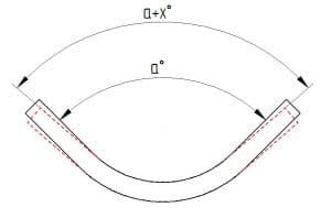
3.5Springback
After bending, metal tends to spring back slightly due to elastic recovery. This deviation, known as springback, typically ranges between 1° to 2°.
Influencing Factors:
- Higher tensile strength → more springback
- Larger bend radius and wider die opening → greater springback
Compensation Methods:
- Use CNC press brakes with automatic springback compensation
- Overbend the part slightly in the design to account for springback
3.6Bending Tolerances
All bending operations inherently involve dimensional tolerances, influenced by material thickness, tolerance grade, and machine precision.
| Parameter | Standard Tolerance | High Precision Tolerance |
| Linear dimensions | ±0.1 mm | ±0.05 mm |
| Bend angle | ±1° | ±0.5° |
| Bend length deviation | ±0.2 mm per bend | ±0.1 mm per bend |
Perfect 90° angles or sharp-corner bends without radii are typically unachievable in standard sheet metal forming.
3.7Bending Force Requirements
The required press force (tonnage) depends on several factors:
- Bend radius (smaller radius → higher force)
- Material type and tensile strength
- Sheet thickness
- Bend length
If certain bends require high forming pressure, it’s essential to verify the press brake’s tonnage capacity in advance.
3.8Heat-Affected Zone (HAZ)
Processes like laser or plasma cutting generate a heat-affected zone near the cut edge. This may lead to:
- Uneven bending due to material hardening
- Microcracks near holes or edges
When incorporating laser cutting, avoid placing high-precision bends too close to the HAZ to ensure consistent forming quality.
Minimum Distance Guidelines for Features Near Bends
To avoid deformation or defects during bending, certain features should be placed at a safe minimum distance from the bend lines. The table below provides recommended spacing formulas based on industry best practices:
| Feature Type | Minimum Distance Guidelines* |
| Between a curl and an internal bend | ±6 times the curl’s radius + material thickness |
| Between a curl and an external bend | ±9 times the curl’s radius + material thickness |
| Between a hem and an external bend | ±8 times the sheet thickness |
| Between a hem and an internal bend | ±5 times the sheet thickness |
| Between a counterbore and a bend | ±4 times the sheet thickness + bend radius |
| Between a countersink and a bend | ±3 times the sheet thickness |
| Between hole and a bend | ±2.5 times the material length + bend radius |
| Between a slot and a bend | ±4 times the sheet thickness + bend radius |
| Between an extruded hole and a bend | ±3 times the sheet thickness + bend radius |
| Between semi-pierced hole and a bend | ±3 times the sheet thickness + bend radius |
| Between a notch and a bend in a perpendicular plane | ±3 times the sheet thickness + bend radius |
| Between a notch and a bend in a parallel plane | ±8 times the sheet thickness + bend radius |
| Between a dimple and a bend | ±2 times the sheet thickness + inside radius of the dimple + bend radius |
| Between rib to a bend perpendicular to the rib | ±2 times sheet thickness + radius of the rib + bend radius |
4.0Main Types of Metal Bending
Metal bending processes vary in method, forming characteristics, and application scope. Each has its pros and cons depending on part geometry, material type, precision, and production volume.
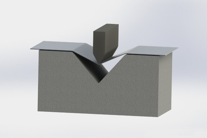
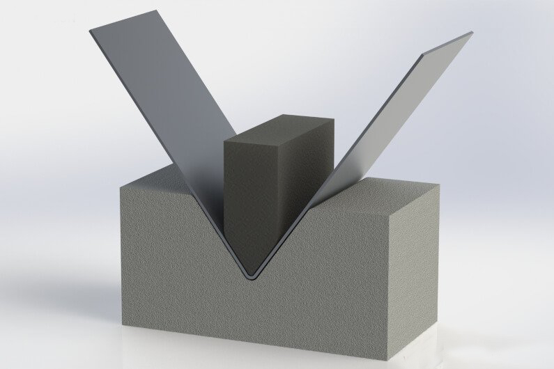
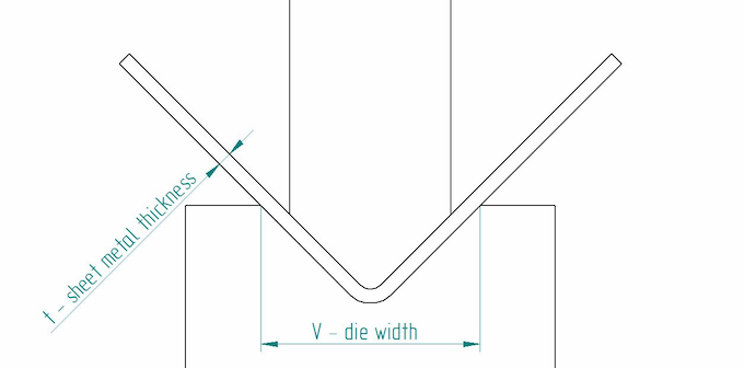
4.1Air Bending
A widely used method where the punch presses the sheet into a V-die without fully bottoming out. Contact occurs at three points: the punch tip and the die edges.
- Advantages: Low tonnage, less die wear, flexible angles with a single die.
- Limitations: Larger springback, relies on CNC compensation.
- Applications: General sheet metal parts
4.2Bottom Bending
The punch pushes the material deeper into the die compared to air bending, but not with full force.
- Advantages: Higher accuracy, minimal springback.
- Limitations: Requires precise tooling, higher tonnage.
- Applications: Medium-volume parts with tight angle tolerance.
4.3Coining
High-pressure bending where the punch fully compresses the sheet into the die, eliminating springback.
- Advantages: Best accuracy, excellent repeatability.
- Limitations: High force and die wear, costly.
- Applications: Aerospace, automotive precision components.
4.4Folding
The sheet is clamped and folded by a beam moving up or down.
- Advantages: Ideal for large panels, minimal surface damage.
- Applications: Enclosures, HVAC ducts, large-format parts.
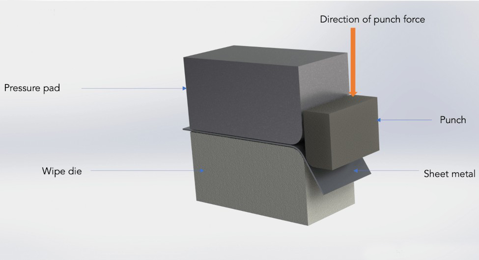
4.5Wipe Bending
The sheet is clamped, and a punch wipes across the edge to form the bend.
- Advantages: Good surface finish, suitable for simultaneous bends.
- Limitations: Angle limited to ~90°, complex tooling.
- Applications: Aesthetic or small-batch precision parts.
4.6Jog Bending (Jogging)
A step-by-step method is used to create Z-shaped or offset profiles.
- Advantages: Flexible, suitable for long parts or reinforcements.
- Limitations: Potential surface wear.
- Applications: Connectors, stiffeners, guide rails.
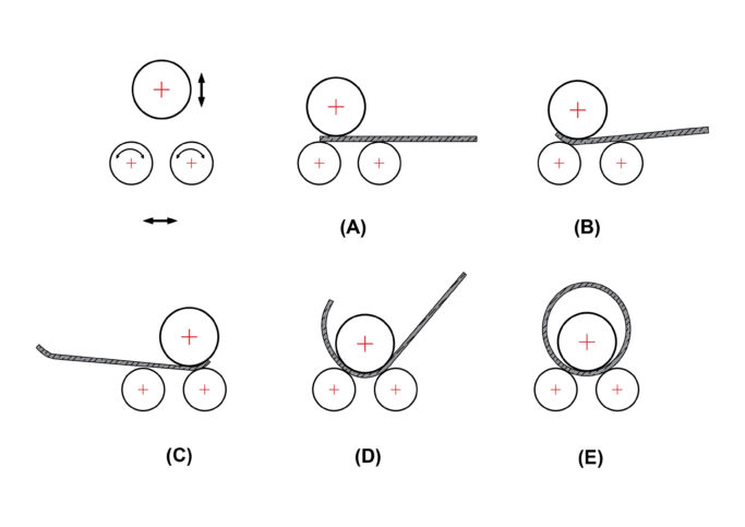
4.7Roll Bending
Uses three or more rollers to gradually bend sheet metal into curves or cylinders.
- Advantages: Smooth, large-radius curves.
- Applications: Cylinders, cones, and towers in the construction and energy industries.
4.8Rotary Draw Bending
Involves a die and a rotating follower; often used with mandrels inside tubing.
- Advantages: High-precision, multi-radius bends up to 180°, low springback.
- Limitations: Complex setup, costly machinery.
- Applications: Tubular structures like exhausts, bike frames, and furniture.
5.0Key Terminology and Geometrical Parameters in Bending
To ensure consistency across design, simulation, and manufacturing, several standard terms and parameters are commonly used in metal bending. Below are the essential definitions:
| Term | Definition |
| Bend Line | The line on the flat pattern where the bend occurs; separates two flanges. |
| Bend Axis | The straight axis around which the material bends; perpendicular to bend line. |
| Neutral Axis | The internal layer of material that remains unstressed during bending. |
| Bend Allowance (BA) | The arc length of the neutral axis between the two bend lines. |
| Bend Deduction (BD) | The amount subtracted from the total flange length to get the flat pattern. |
| K-Factor | Ratio of the distance from the neutral axis to the inside surface, divided by material thickness. |
| Inside Radius (IR) | The radius on the inside surface of the bend. |
| Outside Radius (OR) | The radius on the outside surface of the bend. |
| Leg Length | The length of the material extending from the bend to the edge of the flange. |
| Flange | A flat section of the part on either side of the bend. |
| Bend Angle | The angle formed between the two flanges after bending (typically in degrees). |
6.0Key Bending Terms and Geometric Parameters
| Term | Definition |
| Bend Line | The centerline on the sheet surface indicating where the bend occurs. |
| Outside Mold Line (OML) | The theoretical line formed by the extended outer surfaces of both flanges. |
| Flange Length | The straight-line distance from the sheet edge to the bend line. |
| Mold Line Distance | Distance from the sheet end to the OML; used in flat pattern calculations. |
| Setback | The distance from the bend line to the OML; equals MLD minus flange length. |
| Bend Axis | The axis around which the sheet is bent, typically perpendicular to the surface. |
| Bend Length | The actual length of material involved in the bend along the bend axis. |
| Bend Radius | Distance from the bend axis to the inner surface of the bend. OR = IR + Thickness. |
| Bend Angle | The angle formed between two flanges after bending. |
| Complementary Angle | The supplementary angle to the bend angle (e.g., 90° bend → 90° complementary). |
7.0Ductility Comparison of Common Metals and Bending Recommendations
| Material | Ductility | Bending Recommendations |
| 6061 Aluminum Alloy | Poor – prone to cracking when cold bent | Annealing recommended before bending to improve ductility. |
| 5052 Aluminum Alloy | Excellent | One of the best aluminum types for bending; rarely cracks. |
| Annealed Alloy Steel (e.g., 4140) | Good, depending on alloy | Annealing significantly improves ductility and reduces risk of cracking. |
| Brass | Moderate – depends on zinc content | Higher zinc = lower ductility. Suitable for simple bends; complex bends may require heating. |
| Bronze | Poor | Prone to cracking; heating is usually required. |
| Copper | Very good | Extremely ductile; suitable for complex bends. |
| Cold-Rolled Steel | Moderate | Less ductile than hot-rolled, but offers better dimensional stability. |
| Hot-Rolled Steel | Good | Easier to form than cold-rolled steel. |
| Low Carbon Steel | Excellent | Ideal for cold bending without heating. |
| Spring Steel | Good when annealed | Requires annealing after work hardening to allow further bending. |
| Stainless Steel (304, 430, 410) | Varies | 304 and 430 are bendable; 410 is brittle and prone to work hardening. |
| Titanium | Poor | High strength makes it hard to bend. Use large bend radii and compensate for springback. |
Notes:
- For complex bends, prioritize 5052 aluminum, low carbon steel, or copper.
- For hard alloys (e.g., 6061, bronze, spring steel), annealing or preheating is key to avoid cracking.
- For materials like titanium, stainless steel, and high-zinc brass, trial bending or FEA simulation is recommended to evaluate springback and cracking risks.
Recommended reading: What is Hot Rolled Coil (HRC)?
8.0Common Challenges in Metal Bending and Solutions
| Challenge | Description | Solutions |
| Springback | After the bending force is released, the metal elastically returns, causing angle deviation. | – Overbend in design to compensate for springback – Use CNC press brakes with angle feedback – Select low tensile strength or highly ductile materials |
| Cracking | Cracks form on the outer bend when the radius is too small or the material is brittle. | – Use larger bend radii to reduce strain – Anneal materials beforehand – Choose ductile materials like annealed low-carbon steel or soft aluminum |
| Warping / Distortion | Uneven forces or asymmetric part design cause warping or twisting during bending. | – Ensure accurate die alignment and force distribution – Design symmetrical parts – Check material consistency across batches |
| Surface Damage | Scratches, dents, or imprints appear due to high pressure, worn dies, or friction. | – Apply protective films or polymer pads – Use non-marking or polished dies – Perform post-processing such as polishing or deburring |
| Inaccurate Angles | Deviations occur due to poor equipment accuracy, springback, or die inconsistencies. | – Use angle-sensing CNC systems – Validate and calibrate angles before batch production – Set material-specific compensation tables |
| Inconsistent Thickness | Variations in sheet thickness affect bend quality and uniformity. | – Implement strict incoming material inspection – Use thickness sensors and compensation algorithms – Avoid borderline thickness materials |
| Tool Wear | Repeated stress—especially with hard materials—wears out dies, lowering accuracy. | – Schedule regular tool inspection and polishing – Use wear-resistant materials or coated dies – Rotate dies in high-frequency jobs |
9.0Types of Sheet Metal Bending Machines
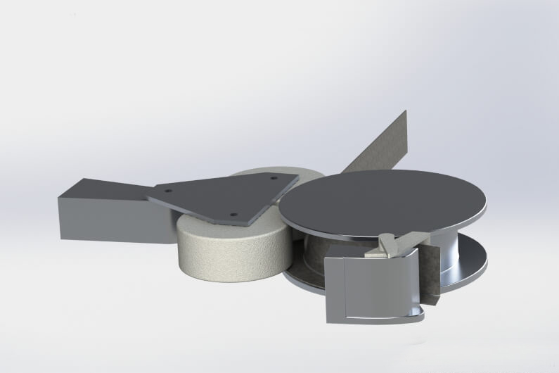
Bending machines are specialized equipment for precise metal sheet bending using punch and die sets. Despite its simplicity, maintaining angle accuracy, repeatability, and material integrity is challenging. They are mainly classified by drive and control type as follows:
- Mechanical Press Brake: Uses a flywheel-driven ram and mechanical transmission to perform bending strokes.
Advantages & Features:
High speed, suitable for high cycle-rate applications; strong mechanical rigidity ensures good repeatability; not ideal for air bending or fine control tasks; lower safety and flexibility compared to modern machines. - Pneumatic Press Brake: Uses compressed air to drive pistons, generating downward force, suited for thin sheets and small parts.
Advantages & Features:
Easy to operate and cost-effective; best for low tonnage, small batch production; suitable for limited space or low power requirements. - Hydraulic Press Brake: Employs hydraulic systems to drive the ram, providing higher and more stable bending forces.
Advantages & Features:
Precisely controllable pressure and stroke; suitable for thick or high-strength metals; can be integrated with CNC for complex bending tasks; widely used in high-precision applications. - CNC Press Brake: The most advanced bending machine, combining hydraulic, servo, electrical, and computer technologies.
Advantages & Features:
Highly automated with program-controlled multi-bend sequences; features angle compensation and springback correction for consistent results; ideal for flexible manufacturing with multiple product types and small batches.
10.0Advantages of CNC Sheet Metal Bending
Among all sheet metal fabrication techniques, CNC bending is often underestimated, yet it offers several significant benefits:
- No need for dedicated dies: Unlike stamping processes, CNC bending does not require special tooling, reducing mold development and maintenance costs.
- Short lead times: Ideal for quick order fulfillment, significantly shortening the turnaround from design to finished product.
- High repeatability and accuracy: CNC equipment enables consistent control over bending angles and dimensions, ensuring uniform quality across batches.
- Strong automation capability: Easily integrates with automated loading/unloading systems and robotic bending cells for enhanced productivity.
11.0Comparison of Sheet Metal Bending and Other Manufacturing Processes
| Process | Best Application Scenario | Typical Accuracy (Tolerance) | Applicable Material Thickness (mm) | Requires Custom Tooling? | Minimum Order Quantity | Lead Time (CAD to First Part) |
| Laser Cutting | Complex geometry, small to medium batch sizes, all scales | ±0.10 mm | 0.5 – 20.0 | No | 1 – 10,000 pcs | Less than 1 hour |
| CNC Bending | Parts with multiple right angles or bends, medium to large | ±0.18 mm | 0.5 – 20.0 | No | 1 – 10,000 pcs | Less than 1 hour |
| CNC Punching | Parts with many holes, embossing, medium to large parts | ±0.12 mm | 0.5 – 4.0* | No (except special dies) | 1 – 10,000 pcs | Less than 1 hour |
| Stamping | Standard geometry, high precision, large batch production | ±0.05 – ±0.10 mm | 0.5 – 4.0* | Yes (cost $250 to >$100,000) | ≥ 5,000 pcs | 25 – 40 days |
| Shearing | Simple shapes, linear cuts, low precision thin sheet metal | ±0.50 mm | 0.5 – 4.0* | No | 1 – 10,000 pcs | Less than 1 hour |
*Note: Thickness ranges marked with * may vary depending on material type and equipment capabilities.
12.0Suitable Manufacturing Scenarios for Sheet Metal Bending
Sheet metal bending is a flexible and efficient metal forming process widely used across various industrial manufacturing sectors. It is especially suited for precise processing of medium and thin gauge metal sheets. With the advancement of automation and CNC technology, its application range and cost-effectiveness continue to expand.
Wide Range of Applicable Materials and Thicknesses
Sheet metal bending can be applied to a variety of metals, including:
Common metals: Carbon steel, stainless steel, aluminum;
Specialty metals: Copper, brass, titanium, nickel alloys, etc.
Although the term “sheet metal” typically refers to metal sheets thinner than 3 mm, modern bending equipment can process materials up to 20 mm thick, particularly for industrial parts requiring large radii and high structural strength.
Applications Across Multiple Industries
Sheet metal bending plays a critical role in the following sectors:
- Automotive & Transportation: Body panels, chassis brackets, dashboards;
- Home Appliances: Refrigerators, washing machines, air conditioner housings;
- Office & Home Equipment: Filing cabinets, metal desks and chairs, lighting brackets;
- Industrial Equipment: Electrical control boxes, cabinets, conveyor frames;
- Construction: Duct systems, handrails, metal fences.
Cost Reduction and Efficiency Improvement
Modern CNC press brakes can work in conjunction with laser cutting machines to produce complex shapes by cutting and bending a single metal sheet, often eliminating the need for additional fasteners or welding:
- Reduces material waste;
- Simplifies assembly processes;
- Shortens delivery lead times;
- Lowers labor costs.
13.0Frequently Asked Questions (FAQ)
What are the basic rules for bending metal sheets?
The bending angle tolerance should be controlled within ±1°.
Maintain a safe distance between threaded holes or slots and the bend line (generally not less than 2.5 times the sheet thickness plus the bend radius).
Use consistent bending radii for all bends whenever possible.
The flange length is recommended to be at least 4 times the sheet thickness to enhance structural rigidity.
How to bend lightweight metal sheets?
- Manual bending: Use simple tools such as pliers or hammers to perform small-angle bends on thin sheets, suitable for prototypes or small batches.
- Clamp bending: Secure the metal in a vise and slowly apply mechanical force to bend it.
- Precision bending: Use bending tools such as press brakes or rolling machines to precisely control the bending angle.
What is the standard sequence for sheet metal bending?
It is generally recommended to bend the shorter edges first, followed by the longer edges, especially for fully enclosed four-sided parts or parts to be welded later. This helps reduce interference and improves assembly efficiency.
Which metal materials are suitable for bending?
- Mild Steel (Low Carbon Steel): Most common, easy to form, low cost.
- Cold Rolled Steel (CRS): Smooth surface, suitable for precision parts.
- Hot Rolled Steel (HRS): Suitable for thicker plates, cost-effective.
- Annealed Alloy Steel: Good toughness, suitable for moderately complex bends.
- Aluminum Alloys (e.g., 5052, 6061): Lightweight but require consideration of springback and cracking risks.
14.0Sheet Metal Bending Process Guide PDF
Sheet metal proces details.pdf
References:
fractory.com/sheet-metal-bending/
salamanderfabs.com/latest-news/what-is-sheet-metal-bending/
www.komaspec.com/about-us/blog/guide-to-sheet-metal-bending/