- 1.0What Is Thread Rolling?
- 2.0Rolling vs. Cutting: A Clear Comparison
- 3.0Advantages of Thread Rolling Over Cutting
- 4.0Material Considerations: The Formability Index
- 5.0Design Guidelines for Rolled Threads
- 6.0Thread Rolling Tooling
- 7.0Operating Parameters: Speed and Feed
- 8.0Thread Inspection and Measurement
- 9.0Conclusion
- 10.0FAQ: Common Issues in Thread Rolling
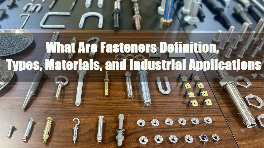
In the world of precision machining, threads are everywhere — from aerospace fasteners to automotive components, from medical implants to industrial hardware.
Traditionally, threads are produced by cutting: removing material with taps, dies, or single-point tools. While cutting is effective, it comes with certain limitations — slower production speeds, weaker threads, and higher costs in large-scale manufacturing.
There is, however, a faster, stronger, and more economical alternative: Thread Rolling.
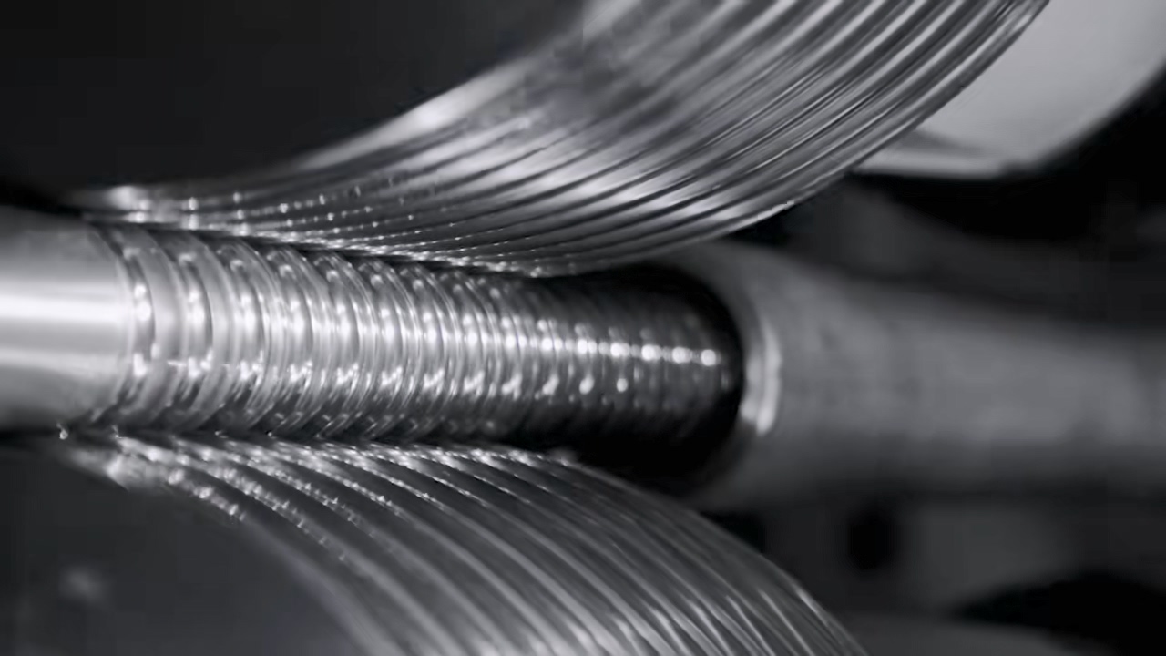
Thread Rolling is a cold-forming process, not a cutting operation. Instead of removing metal, thread rolling displaces and reforms material under pressure, creating threads with remarkable strength, accuracy, and surface quality.
1.0What Is Thread Rolling?
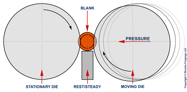
Thread rolling is a cold forming process in which a cylindrical blank is pressed between hardened dies to plastically deform the material into the shape of the thread form. Unlike cutting, which severs the grain structure of the material, rolling preserves and realigns the grain flow in the direction of the thread, creating stronger and more fatigue-resistant parts.
Key characteristics of thread rolling:
- Not a subtractive process— no chips are produced
- Strain hardening effect— material becomes harder and stronger
- Superior surface finish— due to die burnishing during rolling
- High precision— consistent form and dimension
2.0Rolling vs. Cutting: A Clear Comparison
The differences between cut and rolled threads are significant, affecting strength, finish, efficiency, and overall cost. The table below highlights the key contrasts:
| Feature / Aspect | Thread Cutting | Thread Rolling |
| Process Type | Material removal (cutting) | Cold forming (displacement) |
| Strength | Baseline | Up to 30% stronger due to work hardening |
| Surface Finish | Rougher may require secondary finishing | Smooth, continuous, high-quality finish |
| Accuracy / Profile | Depends on tool sharpness and operator skill | High repeatability, precise profile |
| Material Waste | Generates chips | Minimal or no material waste |
| Production Speed | Moderate | Faster, continuous process |
| Tool Life | Short to medium, tool wear from cutting | Longer, depending on material hardness |
| Lead Time | Longer due to stepwise cutting | Shorter, fewer secondary operations |
| Ideal Materials | Most metals, easier on soft metals | Softer metals preferred; harder metals possible but reduce die life |
| Common Issues | Burrs, tool marks, micro-cracks | Slivers, scuffed crests, pitch/helix issues |
From this comparison, it is clear that thread rolling offers significant advantages in strength, surface quality, and efficiency, making it the preferred choice for high-volume production or applications requiring durable threads.
3.0Advantages of Thread Rolling Over Cutting
Why choose rolling over cutting? The benefits are significant:
- Lower Cost
Reduced material waste and longer tool life translate directly to lower production costs. - Higher Efficiency
Rolling is significantly faster than cutting, particularly for high-volume production. - Stronger Threads
Rolled threads can exhibit up to 30–40% greater tensile strength and fatigue life compared to cut threads. - Better Surface Finish
The rolling action burnishes the material, producing a smooth, work-hardened surface. - Improved Accuracy
Rolled threads maintain tighter tolerances and consistent profiles across large batches.
4.0Material Considerations: The Formability Index
Not every material responds to rolling in the same way. The Formability Index is used to evaluate a material’s suitability for thread rolling. Generally:
- Softer materials roll more easily, but may yield average surface finishes
- Harder materials reduce die life, but often produce superior surface finishes
Common Material Behavior in Thread Rolling
| Material | Hardness | Thread Surface | Die Life |
| Brass (345, 360) | < Rb 75 | Good / Poor | Med–High |
| Aluminum (2024-T4, 6061-T6) | < Rb 120 | Excellent / Good | High |
| Stainless Steel (302, 440) | < Rc 32 | Excellent | Med–Low |
| Steel (1018, 12L14) | < Rc 24 | Excellent / Fair | Medium |
Elemental effects:
- Sulfur in steel and bismuth in aluminum can create flake-like defects that reduce surface quality.
- Elements like sulfur, lead, and bismuth aid machinability (cutting) but hinder cold forming (rolling).
The takeaway: selecting the right material — or balancing machinability with formability — is critical.
5.0Design Guidelines for Rolled Threads
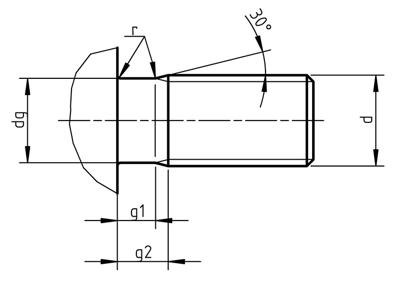
Proper design of the blank and features ensures successful rolling:
Blank Diameter
Recommended blank diameter ≈ : Maximum pitch diameter – 0.002″
Adjustment ratio: every 0.001″ blank change alters major diameter by ~0.003″
Chamfer Angle
Typical: 30° (will form ~45° after rolling)
For harder materials: use 25°–28° to extend die life
Shoulder Clearance
Maintain ≥ 1.25–1.5 × pitch between thread start and shoulder
Thread Length vs. Roll Length
Formula: Roll working face = (2.5 × pitch) + thread length
6.0Thread Rolling Tooling
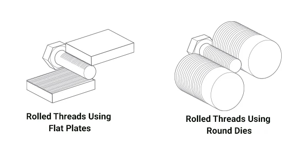
Rolls
- Come in multiple styles for different part orientations
- Material, heat treatment, and coatings impact performance and tool life
- More “starts” on a roll allow higher RPM and extended tool life
Shave Tools
- Provide easy adjustment, repeatability, and rigidity
- Can be designed for various part sizes and support types
Attachments
- Radial Pinch— rapidly clamps and rolls radially
- Axial End Rolling— ideal for threads longer than roll width
- Tangential— fast for high volume, but induces lateral forces
- Axial Rotary Transfer— allows thread rolling adjacent to shoulders
7.0Operating Parameters: Speed and Feed
Thread rolling is often the fastest operation in the process chain.
- General guideline: Workpiece RPM ≈ 300 × roll starts
- Higher rolling speeds usually improve surface finish
- Proper lubrication is critical to reduce friction and extend die life
8.0Thread Inspection and Measurement
Inspection ensures that rolled threads meet functional requirements. Common methods include:
- Go/No-Go Ring Gages— simple and widely used
- Thread Micrometers / Three-Wire Method— accurate measurement of pitch diameter
- Tri-Roll Gages (Johnson Gage)— for assessing functional fit
- Functional and Segmented Gages— to evaluate thread form and flank angles
- NPT / NPTF Gages— for tapered pipe threads
Key Dimensions to Check:
- Blank diameter
- Pitch diameter
- Major diameter
For pipe threads, L1/L2 gages and sextant gages are used to ensure sealability and proper thread form.
9.0Conclusion
Thread rolling is far more than an alternative to cutting — it is a superior manufacturing process for producing high-quality threads. By leveraging cold forming, thread rolling delivers:
- Higher strength
- Lower cost
- Greater efficiency
- Superior accuracy and surface finish
- When paired with the right material, design, tooling, operating parameters, and inspection practices, thread rolling can dramatically enhance product performance and manufacturing productivity.
For industries where strength, precision, and cost efficiency matter most, thread rolling is quickly becoming the new standard in thread production.
10.0FAQ: Common Issues in Thread Rolling
Why do I see slivers or flakes in rolled threads?
This usually happens when the blank material contains unfavorable additives (such as sulfur, bismuth, or lead) or when surface preparation is poor. These inclusions may help machining but hinder cold forming, causing flakes during rolling.
What causes incorrect pitch or lead in threads?
Incorrect pitch/lead is often due to misaligned rolls, wrong setup parameters, or worn tooling. It can also result from incorrect feed rates relative to the roll design.
Why do my rolled threads have a mismatched helix angle?
A mismatched helix angle typically indicates incorrect roll geometry, improper roll selection, or setup errors in the rolling attachment.
Why are rolling results inconsistent between parts or batches?
Variations in material hardness, lubrication quality, or machine stability can lead to inconsistent rolling conditions. Maintaining controlled process parameters is critical.
Can I roll threads on hollow workpieces, closed holes, or out-of-round blanks?
These blanks present major challenges. Out-of-round or non-uniform stock prevents proper thread formation, leading to weak, distorted, or incomplete threads.
Why are my threads filled out in the center but not at the ends?
This happens when chamfer angles are insufficient, blank diameters are incorrect, or roll penetration is not properly adjusted at the entry and exit of the thread.
What causes a poor surface finish on rolled threads?
Rough or dull finishes usually point to inadequate lubrication, worn thread rolls, or rolling speeds that are set too low.
Why is my thread form distorted?
Poor thread form (rounded flanks, incorrect crest shape) often results from wrong blank size, excessive material hardness, or roll wear. Ensuring correct blank preparation and using sharp rolls helps avoid this.
Why are the crests of my threads not fully formed?
Incomplete crests are typically caused by undersized blanks, insufficient roll penetration, or inadequate rolling pressure. Adjusting the blank diameter and ensuring the correct tooling setup can solve this.
What causes scuffed crests on rolled threads?
Scuffed or scratched crests are a sign of misalignment, lack of lubrication, or excessive rolling pressure. Proper alignment and lubrication practices are essential to avoid this defect.
References
brooksforgings.co.uk/processes/thread-rolling
www.fasteners.eu/tech-info/ISO/4755/
www.earnestmachine.co.uk/what-are-the-differences-between-cut-and-rolled-threads/
www.uccomponents.com/rolled-vs-cut-fastener-threads-which-is-better-for-your-application/