1.0Why Do Punches Chip or Crack?
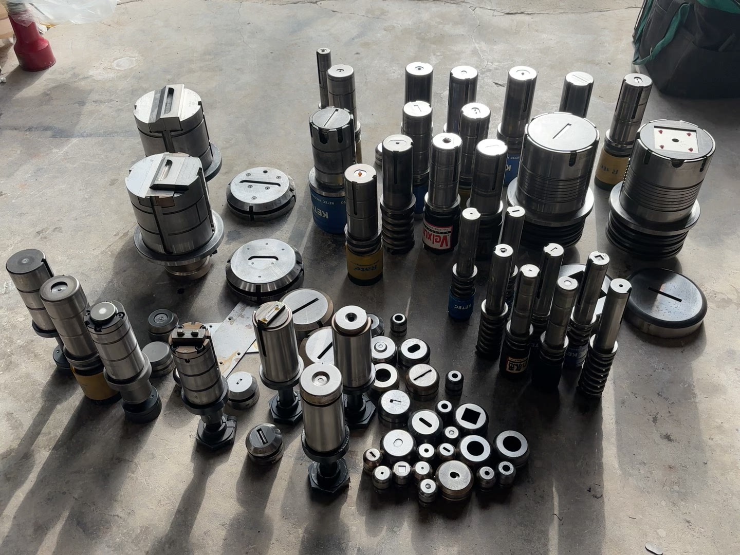
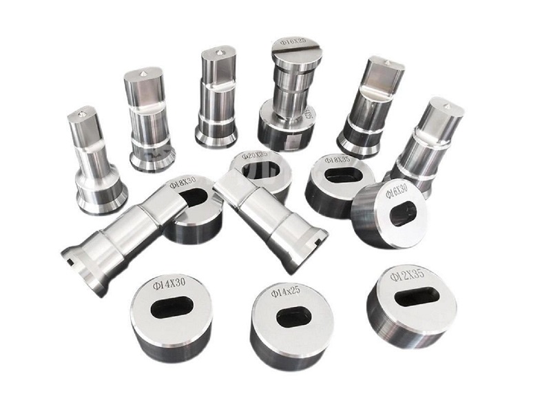
A punch is a high-strength tool component installed on stamping equipment, primarily used to shear metal sheets or other materials into specific shapes. During punching operations, it must withstand significant shearing forces and impact loads, placing strict demands on its material properties, structural design, and usage conditions.
Although modern punches are typically made from shock-resistant tool steels and are precision-machined and heat-treated, various factors during actual use can still cause chipping, corner breakage, or cracking. These failures not only affect product quality and equipment lifespan but may also pose serious safety hazards.
This article provides a systematic analysis of the common causes of punch cracking or breakage. Combined with typical punching equipment and on-site operating practices, it also offers practical recommendations to help extend punch service life and ensure safe, stable production.
2.0Common Causes of Punch Cracking / Chipping and Recommended Solutions
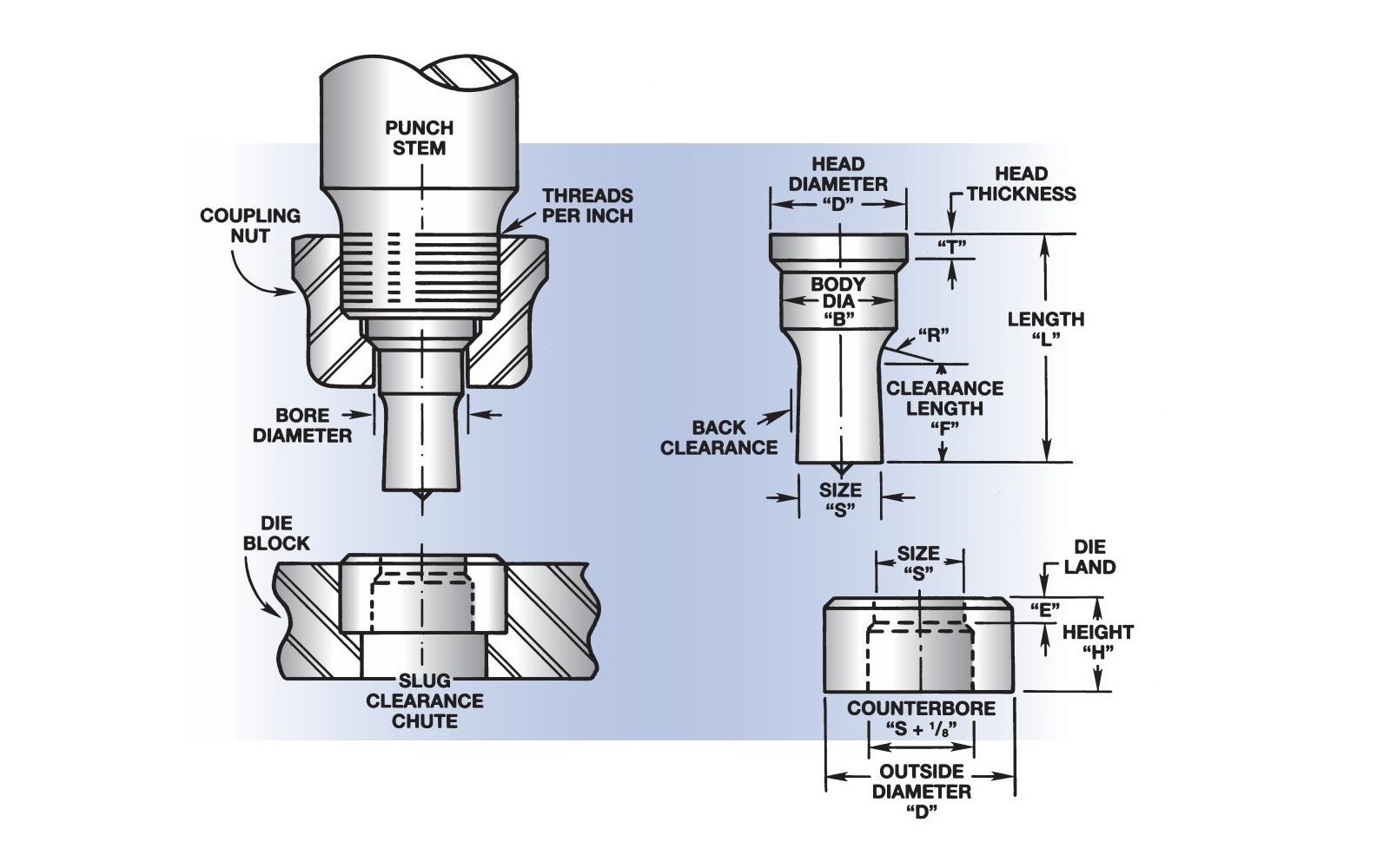
2.1Loose Coupling Nut
Issue: Minor displacement during punching causes uneven force distribution
Solution: Regularly inspect and tighten the coupling nut to ensure the punch is securely installed
2.2Misalignment Between Punch and Die
Issue: The punch is not properly aligned with the die hole, leading to an asymmetric load
Solution: Adjust the die position to ensure concentric alignment between the punch and the die
2.3Improper Clearance Setting
Standard Clearance Reference:
- Material thickness 1/8″–1/2″: 1/32″ total clearance
- Material thickness 1/2″–3/4″: 1/16″ total clearance
- Over 3/4″ thick material: 3/32″ total clearance
Solution: Select the proper clearance based on material thickness to avoid damaging the punch or die
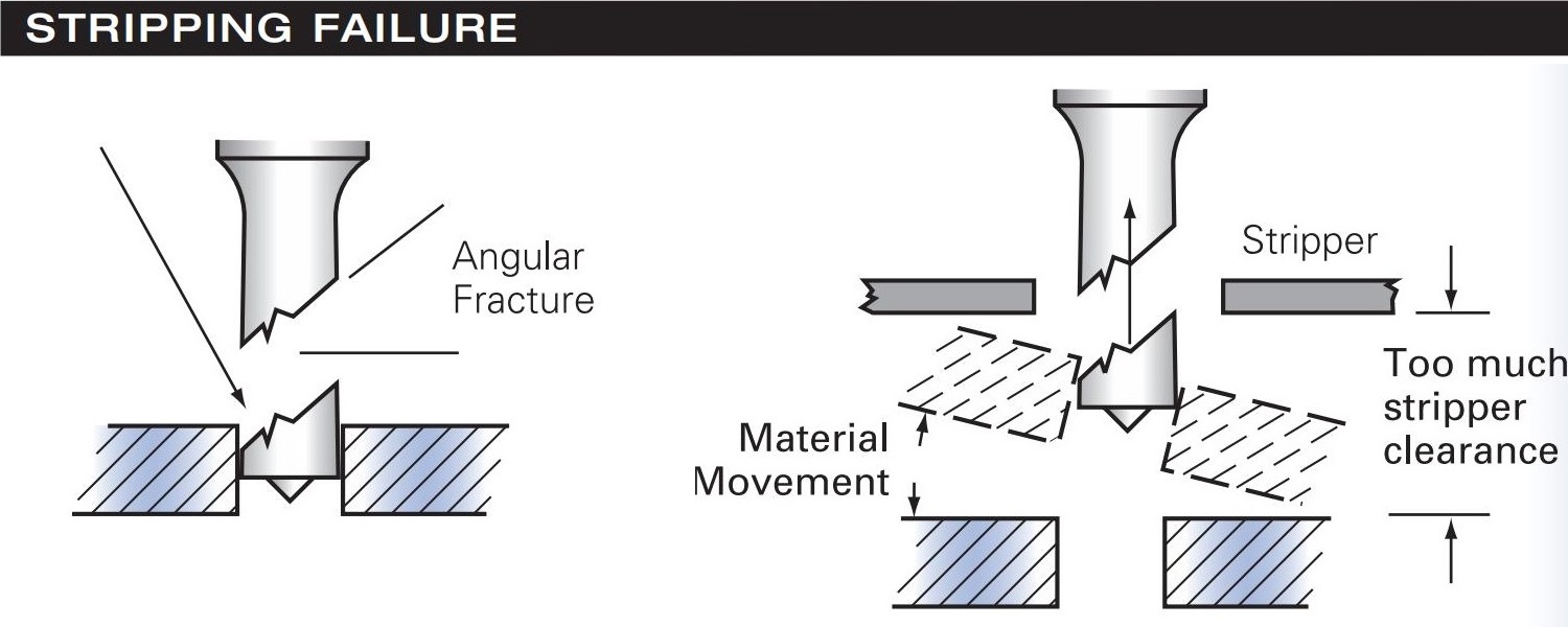
2.4Uneven Stripping
Issue: During the upward stroke, the sheet is not properly held down, concentrating stress on one side
Solution: Inspect and adjust the stripper mechanism to ensure even pressure across the work surface
3.0Common Punch Failures, Causes, and Solutions
3.1Fractured Punch Tip
- Failure: A portion of the punch is broken off and remains in the material.
- Probable Cause: Excessive stripper clearance.
- Solution: Adjust the stripper closer to the material surface to apply even holding pressure.
3.2Chipping or Galling on Punch Face
- Failure: Punch face shows localized chipping or heavy galling.
- Probable Cause: Misalignment between punch and die, causing drag.
- Solution: Realign the punch and die to ensure equal clearance around the perimeter.
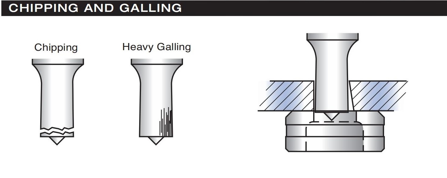
3.3Compressive Failure
- Failure: The Entire working end of the punch shatters.
- Probable Cause: Punching extremely hard or thick materials, or complete punch-die misalignment.
- Solution: Use high-toughness punches for demanding applications.

3.4Punch Head Breakage
- Failure: The head of the punch fractures or breaks off.
- Probable Cause: Loose or worn coupling nut or uneven punch stem contact.
- Solution: Regularly check and re-tighten the coupling nut; ensure the punch stem face is smooth and flat.

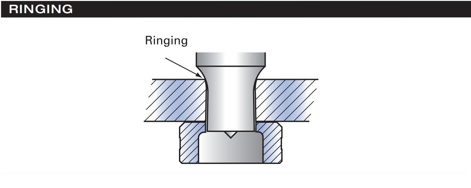
3.5Material Deformation (Ringing)
- Failure: The Material shows signs of warping or bulging with each stroke.
- Probable Cause: Punch enters too deeply into the die, or the material is too thick for the punch length.
- Solution: Adjust stroke depth to limit punch entry into the die to no more than 1/16″.
4.0Proper Slug Appearance and Common Failure Indicators
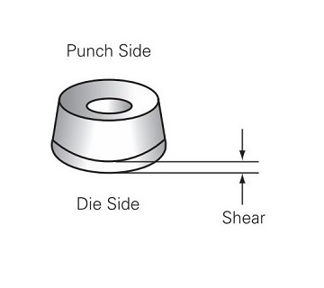
4.1Correct Slug Appearance (Standard Setup)
- Punch Side: Should display a center point indentation and a slight burr.
- Die Side (when punching mild steel 1/8” or thicker): Typically dished in shape.
- Slug Sidewall: A clean, shiny shear surface should be visible on 10%–20% of the material thickness.
4.2Double Shear
- Failure Indication: Two shear planes on the slug.
- Cause: Insufficient clearance between punch and die.
- Solution: Increase punch-to-die clearance.

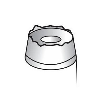
4.3Uneven Burr
- Failure Indication: Burr appears irregular or inconsistent around the slug.
- Cause: Worn tooling or misalignment of punch and die.
- Solution: Inspect tooling condition; realign or replace worn components.
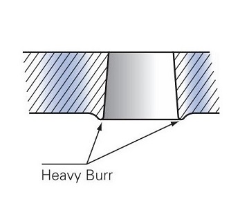
4.4Heavy Burr
- Failure Indication: Large burr on the die side of the slug.
- Cause: Excessive clearance between punch and die.
- Solution: Decrease the die clearance to match the material thickness.
5.0Common Equipment Types for Punches
Punches are widely used in the following types of equipment:
- Punch Press
Traditional mechanical or hydraulic punch presses are used for general stamping operations. - CNC Turret Punch Press
Suitable for complex shapes and multi-hole punching, featuring automatic tool changes for high efficiency. - Progressive Die Press
Ideal for progressive stamping with multiple stations, where each step is automatically linked for continuous forming. - Hydraulic Punching Machine
Commonly used for punching applications in industries such as steel structures, angle steel, and electrical enclosures. - Ironworker Machine
A versatile machine used in metal fabrication shops for punching, shearing, notching, and bending steel plates and profiles. Especially useful for structural steelwork and small-batch production tasks.
6.0Safety Reminders
Operators are responsible for complying with OSHA regulations and ANSI B11.5 stamping safety standards by using proper tooling and following standard operating procedures to ensure personal and equipment safety.
- Always check that punches and dies are securely installed before operation.
- Never place hands inside the die area while the machine is running.
- Wear safety glasses, safety shoes, and protective gloves during operation.
- Verify that safety devices (e.g., light curtains) are functioning properly before use.
- Disconnect power before replacing or servicing punches.
- Regularly inspect coupling nuts, stripping devices, and punch-to-die clearance.
- Only trained personnel are permitted to operate punching equipment.
- Immediately stop the machine to investigate any unusual noises or poor punching quality.
7.0Frequently Asked Questions (FAQ)
Q1: Why do punches chip or crack?
A1: Punch chipping or cracking usually results from loose coupling nuts, misalignment with the die, improper clearance, or uneven stripping, causing uneven forces on the punch.
Q2: How can I prevent punch chipping and cracking?
A2: Regularly tighten coupling nuts, ensure proper punch-to-die alignment, set correct clearance based on material thickness, and adjust the stripper to apply even pressure.
Q3: What is punch-to-die clearance, and how should it be set?
A3: Clearance is the gap between the punch and the die. Recommended standards are: 1/32″ total clearance for 1/8″–1/2″ thick materials, 1/16″ for 1/2″–3/4″, and 3/32″ for thicker than 3/4″.
Q4: What should I do if punches break frequently?
A4: Collect broken punches and material samples, send them to your supplier or manufacturer for analysis, and consider using tougher punches or adjusting process parameters.
Q5: What safety precautions should be followed when operating punching equipment?
A5: Ensure tooling is securely installed, wear appropriate PPE, keep hands away from the die area during operation, regularly check safety devices, and disconnect power before maintenance.