Detailed Overview of Plate Rolling: Three-Roll, Four-Roll, and Tapered Forming Methods
1.0Introduction to Plate Rolling
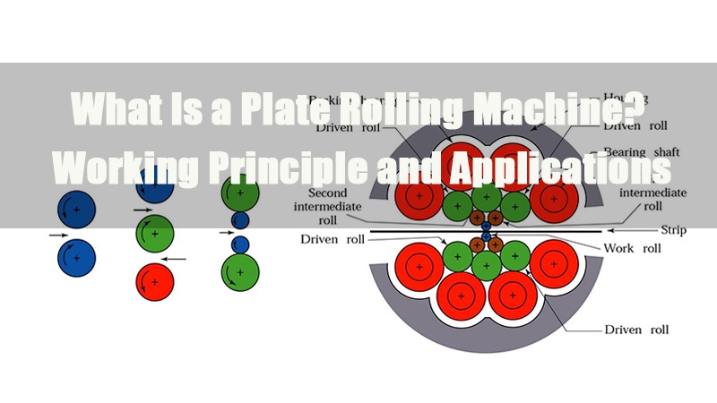
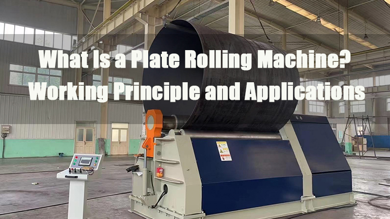
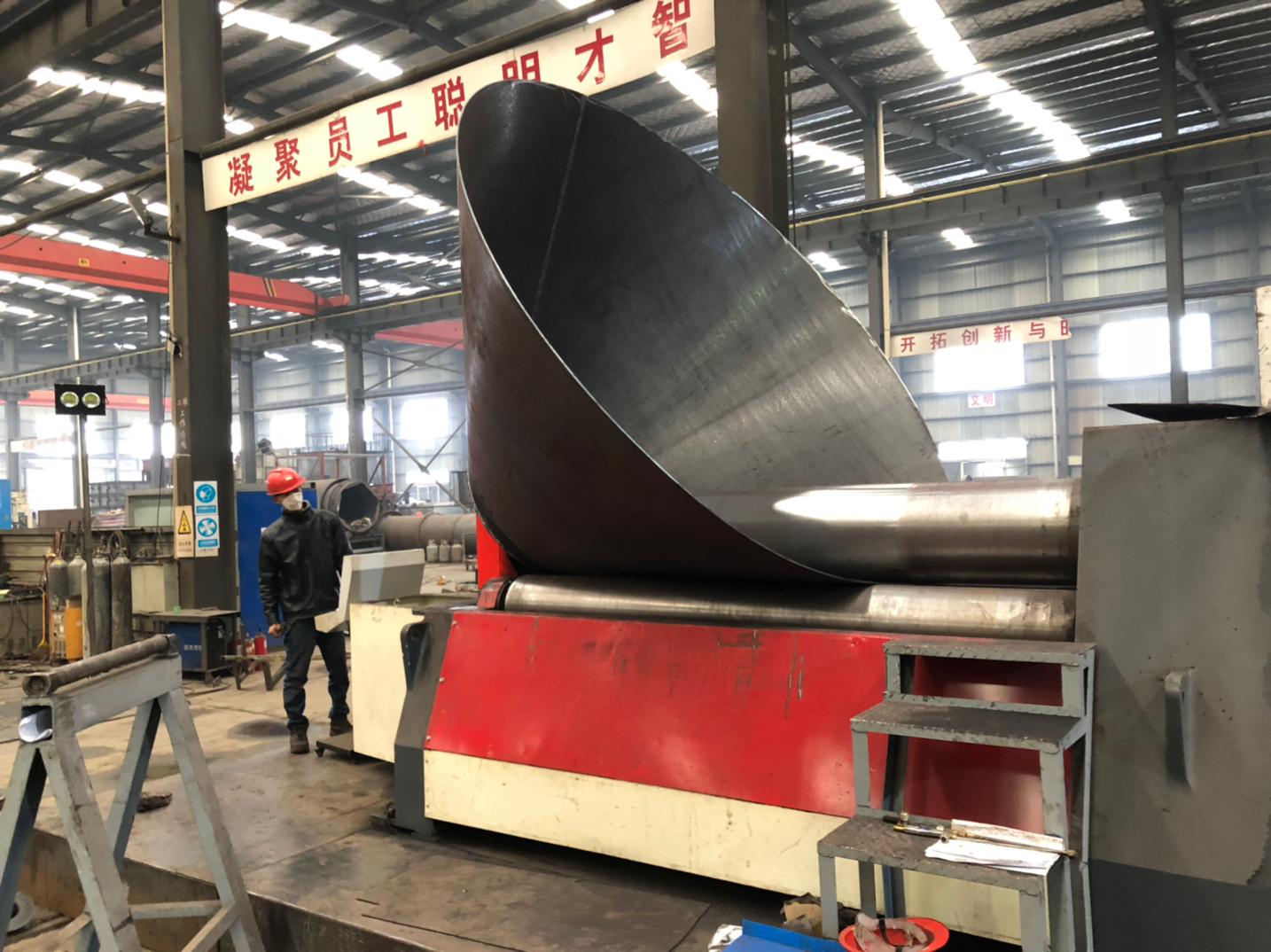
Plate rolling is a metal forming process used to shape flat sheet metal into cylindrical, conical, elliptical, or other curved profiles. During this process, the sheet is passed through a set of rolls that apply continuous and controlled pressure, gradually bending the material into the desired geometry.
This method is typically used for parts with larger bending radii and is widely applied in the manufacturing of cylindrical and conical components. In addition, by adjusting the position of the roller shafts relative to the feeding direction, it is possible to produce cylindrical parts with non-circular cross-sections, such as rectangular or elliptical shapes. The process can also be used for flanging operations on both circular and non-circular cylindrical parts, as illustrated in Figure 2.
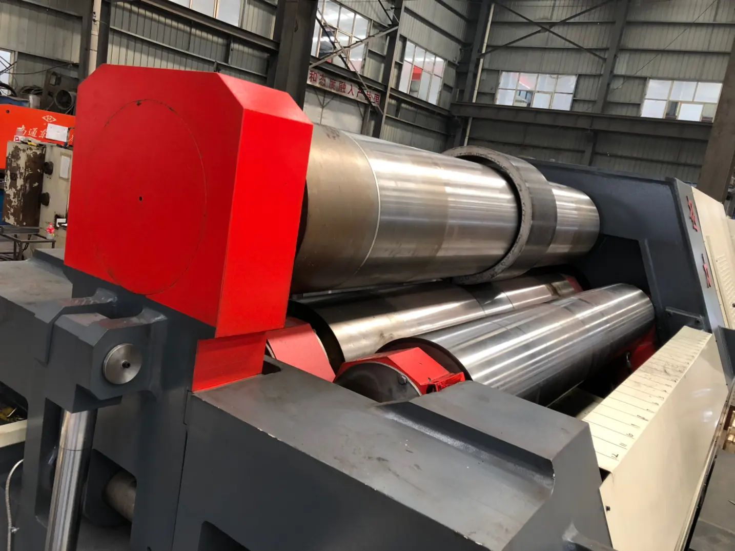
2.0Plate Rolling with Three-Roll and Four-Roll Machines
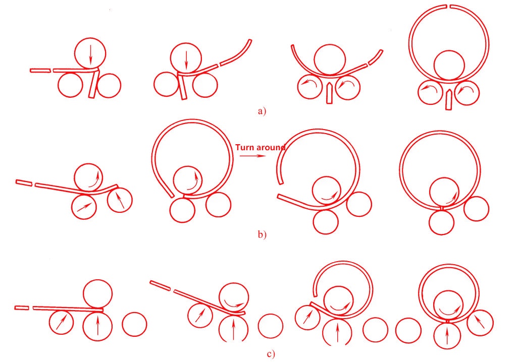
2.1Pre-Bending Process
When using three-roll or four-roll plate rolling machines to form cylindrical shapes, a portion of the plate near the entry and exit edges often remains unbent. This is due to the limited deformation zone between the rolls, which results in straight edges at both ends of the sheet. These unbent areas can lead to gaps or incomplete curvature at the seam, compromising the assembly accuracy and structural integrity of the final product.
To eliminate this issue, a pre-bending operation is performed before the main rolling process. This ensures that the ends of the sheet are slightly curved in advance, effectively reducing the straight edge length and enhancing the overall roundness of the rolled cylinder.
Common pre-bending methods include:
- Top roll bending method(used for symmetrical three-roll machines)
- Side roll pre-bending method(used for four-roll or asymmetrical three-roll machines)
- Multiple-pass feeding and bending method(for thick plates or high-precision applications)
Note: The quality of the pre-bend directly affects the roundness, joint accuracy, and welding performance of the final cylinder, making it a critical step in the plate rolling process.
(Figure 3: Illustration of Pre-Bending Methods)
2.2Rolling Process
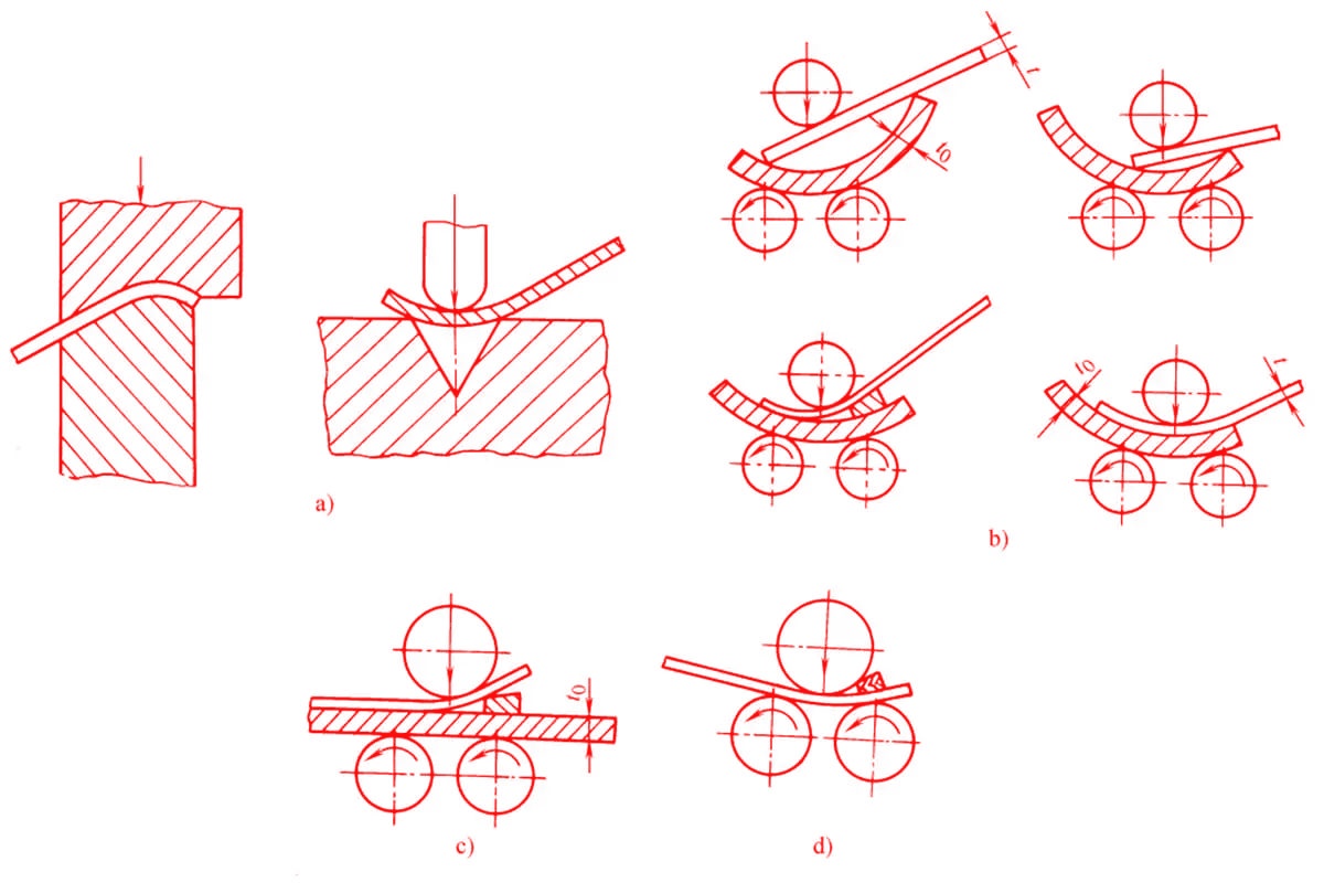
The core operation of plate rolling involves continuously bending a flat sheet into a cylinder, cone, or other curved profile. While the basic principle is the same, different machine structures employ different rolling techniques, as illustrated in Figure 4.
Figure 4 – Rolling processes for various machine types:
- a) Symmetrical three-roll machine with bending edge pad
- b) Asymmetrical three-roll machine
- c) Four-roll machine
- d) Eccentric three-roll machine
- e) Symmetrical downward-adjustable three-roll machine
- f) Horizontal downward-adjustable three-roll machine
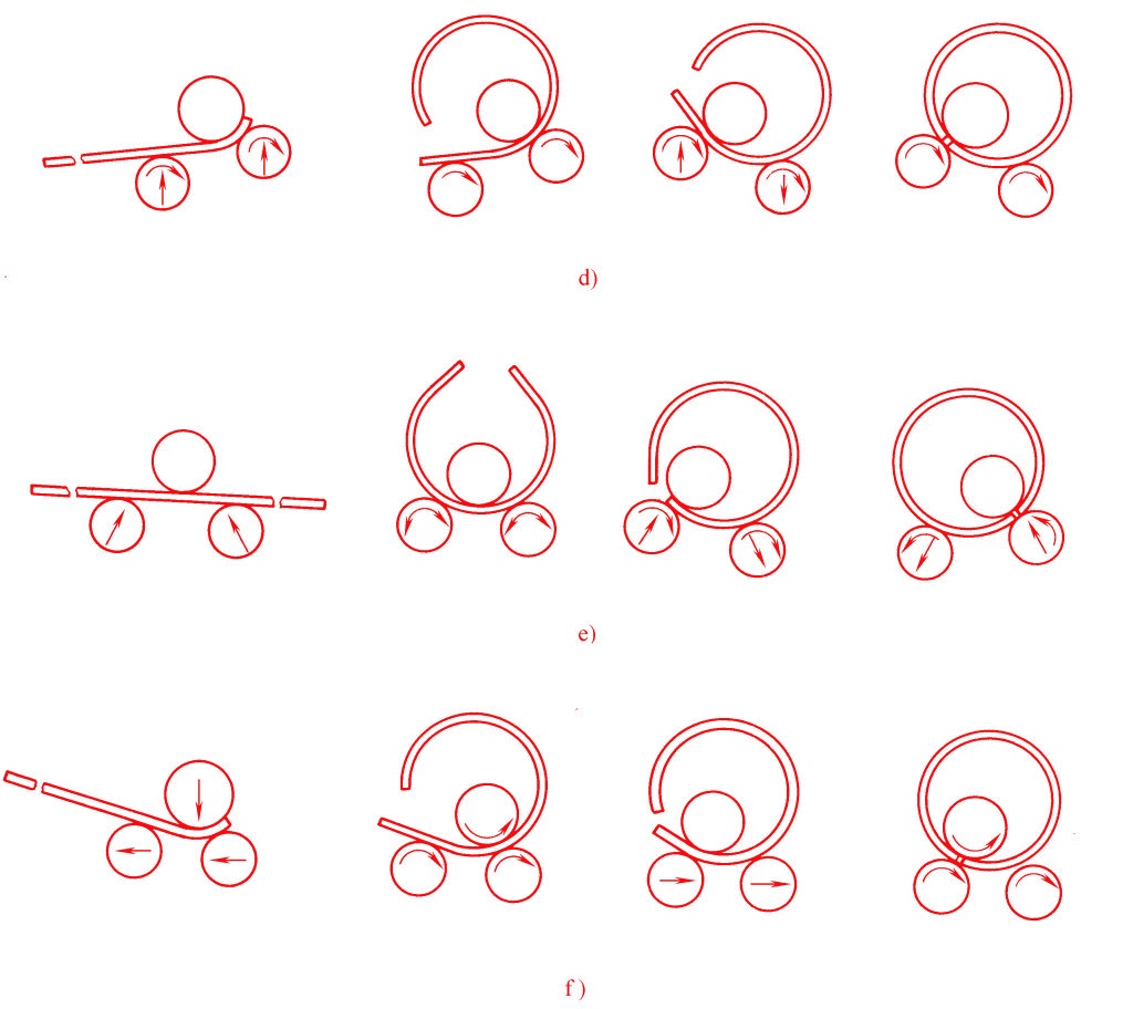
Each type of plate rolling machine differs in:
- The relative movement of the top and bottom rolls
- Whether pre-bending capability is included
- The degree of automation in the feeding process
- Suitability for specific plate thicknesses and precision requirements
Selecting the right machine type and mastering the corresponding rolling method is essential to ensure rolling accuracy, improve production efficiency, and extend equipment lifespan.
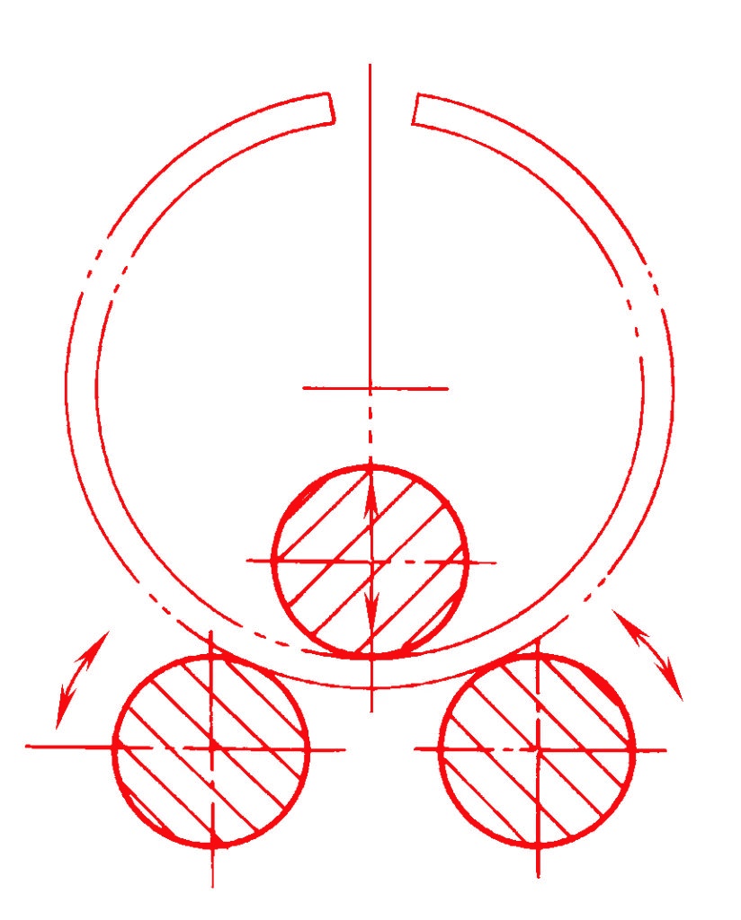
2.3Roundness Correction
After the initial rolling, the cylinder may exhibit roundness deviation or inconsistent curvature, especially at the seam area, as well as at the starting and ending points of the rolling process. To achieve the required roundness tolerance, a roundness correction procedure is carried out.
Correction steps:
- Adjust the roll positions to achieve the maximum corrective curvature.
- Perform 1–2 rolling passes to even out the cylinder’s curvature.
- Gradually reduce the applied pressure, and roll the part several times under decreasing load;
- Continue until the cylinder reaches the desired roundness under minimal pressure.
This step helps to relieve residual stress, correct localized deformations, and is essential for producing high-quality rolled components.
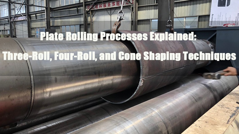
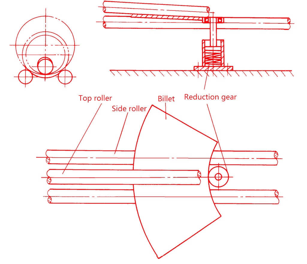
3.0Cone Rolling Methods and Techniques
When manufacturing conical workpieces, the rolling process differs significantly from that of cylindrical parts. To achieve a uniform taper, the metal plate is typically pre-cut into a sector-shaped blank, and the relative positioning of the rolls must be carefully adjusted.
In practice, this is achieved by offsetting the top roll and side roll at an angle (i.e., making them non-parallel) and ensuring that the rolling path always aligns with the generatrix of the cone. This technique allows for continuous cone rolling and enables precise control over the taper angle and curvature distribution.
3.1Common Methods for Cone Rolling:
Precision Forming Methods:
- Reduced Feed at Small End:
Uses friction or damping devices to slow down the feed rate at the smaller end, controlling the difference in linear velocity between both ends. - Dual-Speed Four-Roll Method:
A four-roll plate rolling machine is used to independently drive the large and small ends, ensuring synchronized angular velocity. - Rotary Feed Method:
Guide rollers are installed at both ends of the plate to control its rotation during feeding, ensuring the rolling trajectory aligns with the cone’s generatrix.
Approximate Forming Methods:
- Segmental Rolling Method:
The top roll is repositioned in stages to roll different sections of the plate sequentially, gradually forming a conical surface. - Rectangular Feed Method:
A rectangular blank is rolled in multiple directions to approximate the contour of the cone.
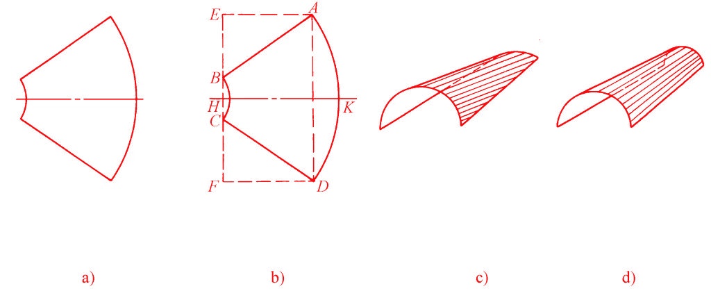
3.2Rectangular Feed Method (Figure 5)
In this method, the plate is cut into a rectangular shape and formed into a cone via directional rolling:
- First, the central section is rolled with the top roll parallel to line HK, creating a near-cylindrical segment (c).
- Next, the top roll is adjusted to be parallel to lines AB and CD to bend the two sides.
- Finally, this results in a conical surface approximation (d).
This method is suitable for symmetric cones or cone segments, and is relatively simple to operate, making it ideal for small to medium-sized workpieces.
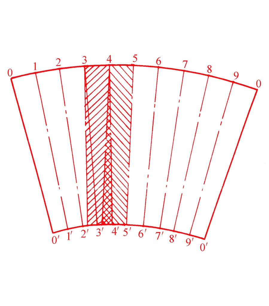
3.3Segmental Rolling Method (Figure 6)
This technique uses staged positioning of the top roll to progressively form the cone:
- Align the top roll with the 5–5′ line, and roll until the large end reaches point 4.
- Move to the 4–4′ line, rolling until the large end reaches point 3.
- Continue in this sequence until all sections are rolled.
This method mimics the effect of non-uniform linear speeds, and is particularly effective for large taper angles or elongated conical shapes.
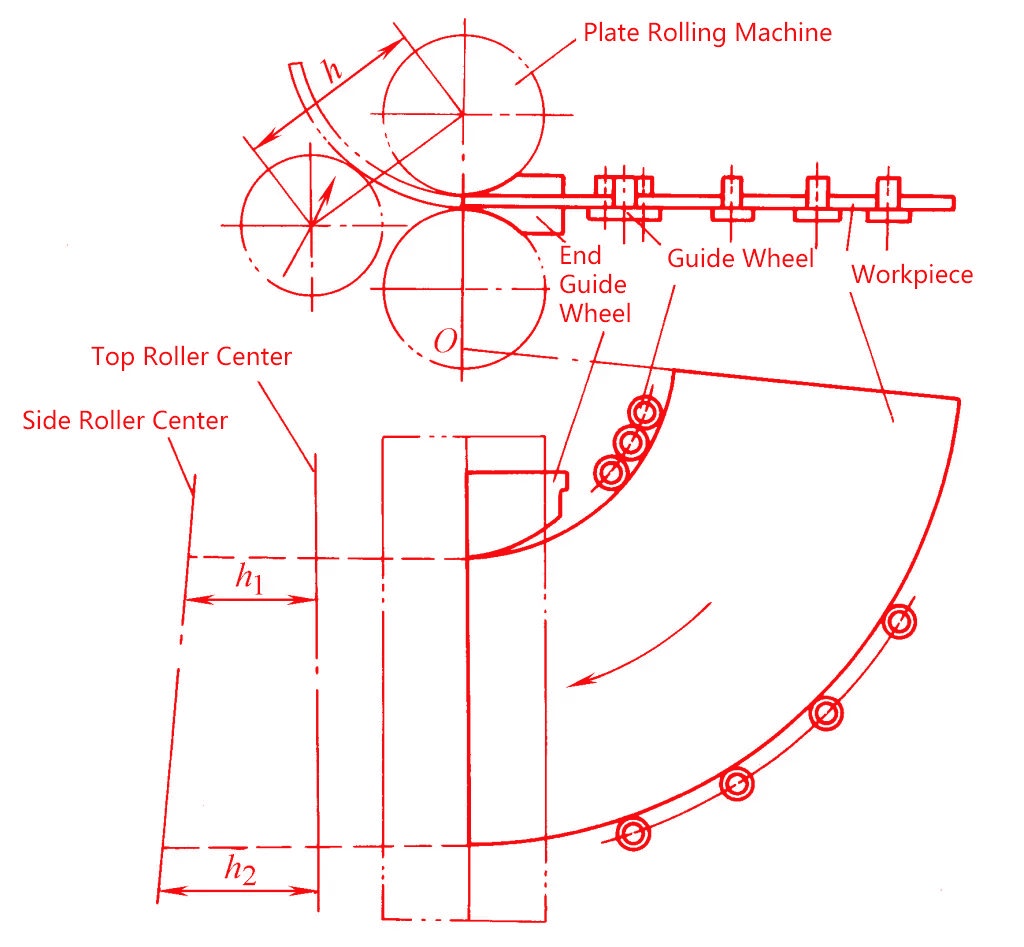
3.4Rotary Feed Method (Figure 7)
Guide wheels are installed on both the large and small ends of the blank. During rolling, the blank rotates forward under guidance, ensuring the movement trajectory closely follows the cone’s generatrix.
This method minimizes misalignment during forming and improves the consistency of the final conical shape.
3.5Reduced Feed at Small End (Figure 8)
By adding a frictional or resistive mechanism at the small end of the blank:
- The feed speed at the small end is intentionally slowed, balancing the linear velocity difference between ends.
- This method is effective for controlling taper curvature progression and is simple in structure, compatible with standard plate rollers.
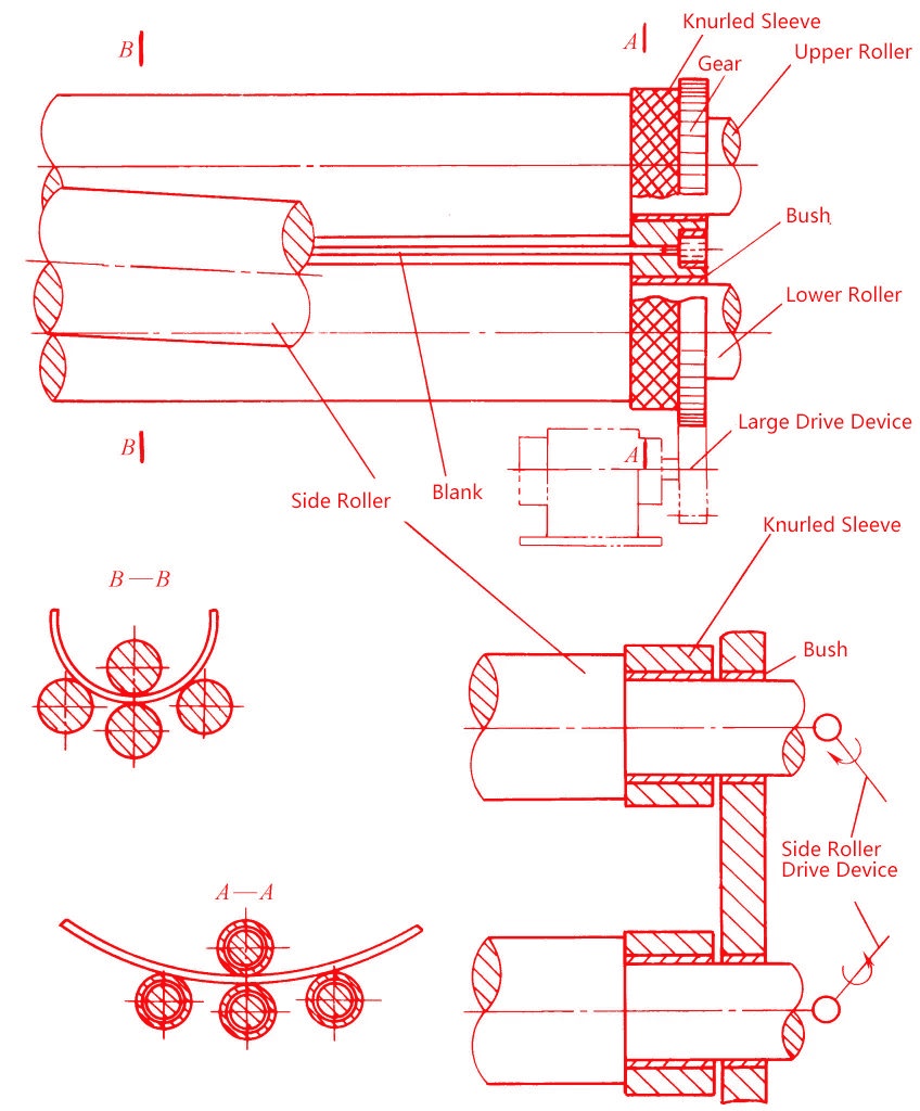
3.6Dual-Speed Four-Roll Machine (Figure 9)
In this approach, a four-roll machine with dual-speed drive independently controls the rolling speed at both ends:
- The top and bottom rolls drive the larger end,
- While the side rolls drive the smaller end.
By maintaining consistent angular velocity, this setup ensures synchronized feeding and achieves high-precision cone forming.
This equipment is well-suited for thick plates, large taper angles, or mass production of high-accuracy conical parts.
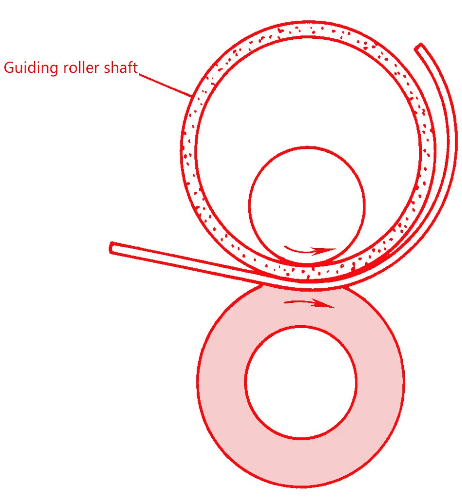
4.0Dual-Axis Bending (Two-Roll Plate Rolling)
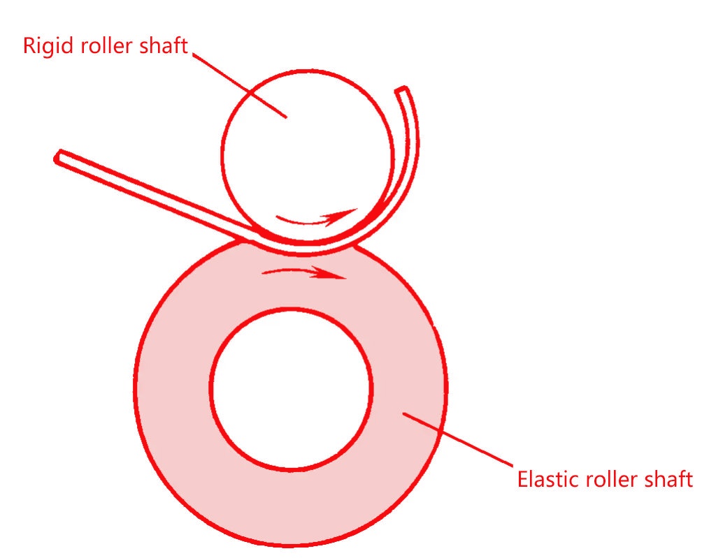
As the sheet is fed between the two rolls, it bends under the rebound force of the elastic roll, which also drives the sheet forward, completing the continuous rolling process.
4.1● Relationship Between Roll Indentation and Finished Diameter
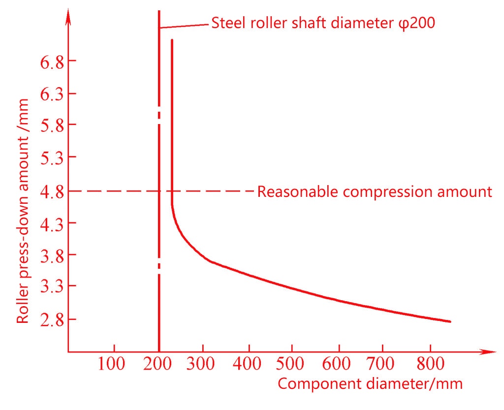
4.2● Adjusting the Final Diameter
4.3● Forming Strategies
Depending on the material properties and sheet thickness, different forming strategies can be applied:
- Single-Pass Forming:
Suitable for materials with good ductility(elongation δ > 30%) or thin sheets with a thickness between 5–4 mm. - Stepwise Bending:
For low-ductility or thicker materials, higher forming forces are required. Pre-bending at the sheet ends is necessary, and intermediate annealing may be applied if needed.
4.4● Advantages of Two-Roll Rolling Technology:
- High production efficiency:
Typical output ranges from 100–350 pcs/hour, with a maximum of up to 1000 pcs/hour. - Excellent dimensional accuracy and surface finish:
Ideal for parts with tight tolerance and high surface quality - Minimal straight edge at ends:
For thin sheets, the straight edge is shorter than the sheet thickness; for thick sheets, it does not exceed 4 times the thickness, eliminating the need for extra pre-bending. - Robust process adaptability:
Even when the blank contains holes, notches, or profiled features, the process remains stable, avoiding cracks or irregular bends.
4.5● Limitations of the Two-Roll Process:
- Inconvenient changeover:
Changing the diameter requires replacement of guide rolls, making the system unsuitable for multi-variety, small-batch production. - Limited size range:
Applicable to sheet thicknesses of up to 3 mm(mild steel) and bending diameters between φ76–φ460 mm.
5.0Typical Applications and Industry Coverage of Plate Rolling Technology
As a critical metal forming process, plate rolling offers high precision and strong adaptability, making it widely applicable across numerous industrial sectors. It enables the fabrication of cylindrical, conical, elliptical, non-circular, and custom-profiled components, supporting both standardized and custom-built structures. The typical applications and covered industries are outlined below:
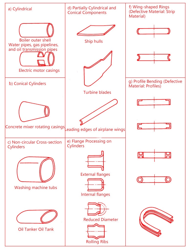
5.1■ Common Types of Formed Components
- Cylindrical Parts:
Including boiler shells, water pipes, gas pipelines, and oil transmission tubes, which form the core structures of pressure vessels and piping systems. - Conical Structures:
Used in manufacturing cone-shaped shells, concrete mixer drums, funnels, diffusers, and tapered ship hull sections. - Non-Circular Cross-Section Shells:
Such as elliptical cylinders and rectangular transition shells, widely used in wind turbine towers, washing machine drums, and other special-shaped components. - Flanging and Necking Operations:
Supports external/internal flagging and diameter reduction, commonly applied in oil tanks, liquid storage vessels, and chemical reactors. - Compound Structures with Arcs and Cones:
Enables fabrication of complex contours, such as motor housings, aircraft wing leading edges, and turbine blades. - Profile Bending:
Suitable for strip and section materials, used in precise bending of components like aerospace rings, supporting collars, and architectural arches.
5.2■ Key Industry Applications
- Pressure Vessel Manufacturing:
Form cylindrical shells, end caps, and special-shaped parts with high pressure-tightness and structural integrity, widely used in boilers, reactors, and storage tanks. - Oil & Gas and Chemical Industry:
Supports the production of large pipelines, oil storage tanks, and chemical containers, meeting high strength requirements for both onshore and offshore - Shipbuilding and Offshore Engineering:
Involves rolling of hull plates, double-curved panels, bulkheads, and deck components, enhancing structural stability and hydrodynamic performance. - Aerospace Sector:
Meets stringent requirements for high-precision, complex-surface forming, applicable to aerodynamic structures, thruster casings, and wing components. - Architecture and Infrastructure:
Fabricates curved beams, arched columns, and other structural elements used in bridges, stadiums, and landmark buildings, where both structural integrity and aesthetic appeal are essential. - Machinery and Heavy Equipment Manufacturing:
Used in forming protective shells, casings, and structural components for equipment like cranes, compressors, and turbines.
Plate rolling technology is applicable to a wide range of materials, including carbon steel, aluminum, stainless steel, titanium alloys, and profiled sections. It not only supports traditional manufacturing needs but also fulfills the high precision, strength, and customization demands of advanced equipment manufacturing, making it an indispensable core process in modern industrial production.