This guide provides an overview of the principles, equipment components, operational methods, typical applications, and technical advantages of Plasma Arc Welding (PAW) and Plasma Arc Cutting (PAC). It is designed to help manufacturers and technical professionals gain a deeper understanding of the process and improve production efficiency.
1.0Plasma Arc Welding (PAW)
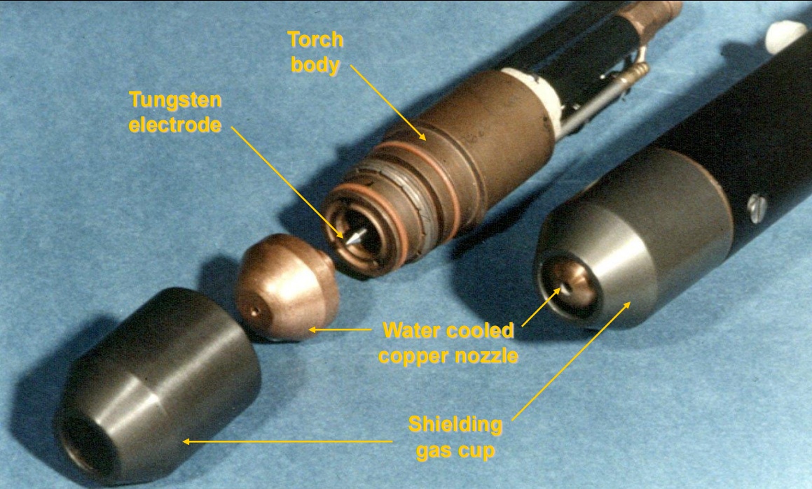
1.1Plasma Welding Torch:
The plasma torch is the core component of a PAW system. Its internal structure includes a tungsten electrode, copper nozzle, water cooling system, and gas channels. Due to the extremely high temperatures involved in welding, the torch must be equipped with an effective cooling mechanism—typically a water-circulation system—to prevent overheating and damage. Handheld torches are relatively large and mainly used for stationary setups, requiring precise alignment of the electrode and nozzle coaxiality.
1.2Gases for Plasma Welding:
Common plasma gases and their applications include:
- Pure argon: Suitable for carbon steel, titanium, and zirconium.
- Argon + 5–15% hydrogen: Used for stainless steels, nickel alloys, and copper alloys; increases arc temperature and weld penetration.
- Argon + ≥40% helium: Applied in high-heat-demand welding; raises arc temperature but reduces nozzle life.
Shielding gases—such as argon, helium, or their mixtures—are used to protect the weld pool from oxidation.
- Shielding gases: Same as used in TIG welding.
- Shielding gas flow rate: 10–30 l/min.
- Back purging: Same as TIG, also required for keyhole welding.
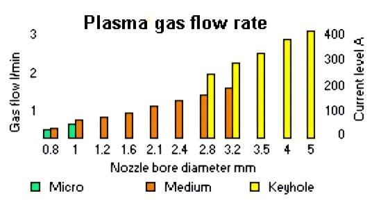
1.3Types of Plasma Arc Welding:
Based on current range and application, PAW is categorized into:
- Micro-plasma (0.1–15A): Suitable for precision welding of small components.
- Medium current (15–200A): Covers most general welding tasks.
- Keyhole plasma (>100A): Designed for deep-penetration welding of thick sections.
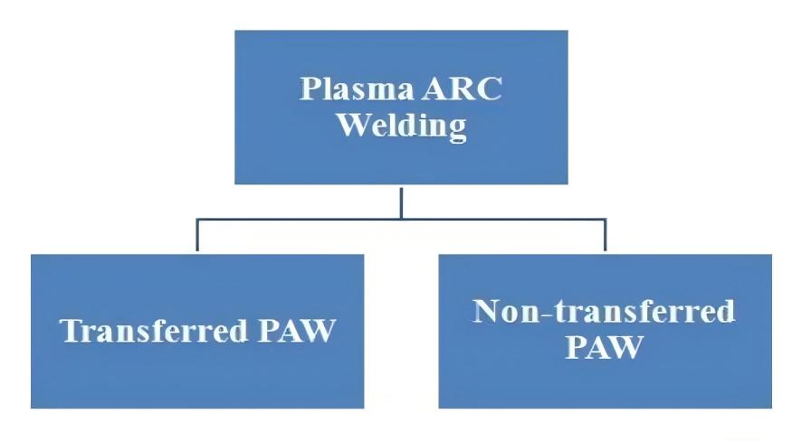
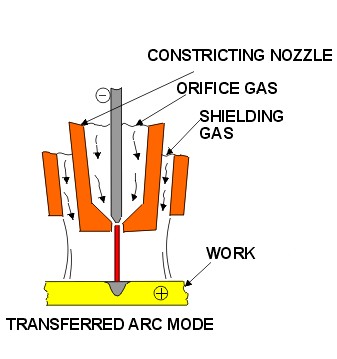
1.4Transferred Arc Mode:
In this mode, the arc is established between the electrode (–) and the workpiece (+), making the workpiece part of the electrical circuit.
Key features:
- High energy density, ideal for high-speed welding and thick materials.
- The arc directly contacts the workpiece, concentrating heat input.
- Commonly used for welding steel, aluminum, copper, and titanium.
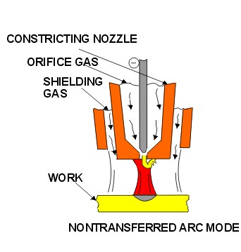
1.5Non-Transferred Arc Mode:
Here, the arc forms between the electrode (–) and the nozzle (+), without involving the workpiece in the circuit.
Key features:
- Heat is delivered via the plasma jet emitted from the nozzle.
- Suitable for welding thin materials or processing non-conductive workpieces.
- Common in cutting operations and surface applications like hardfacing.
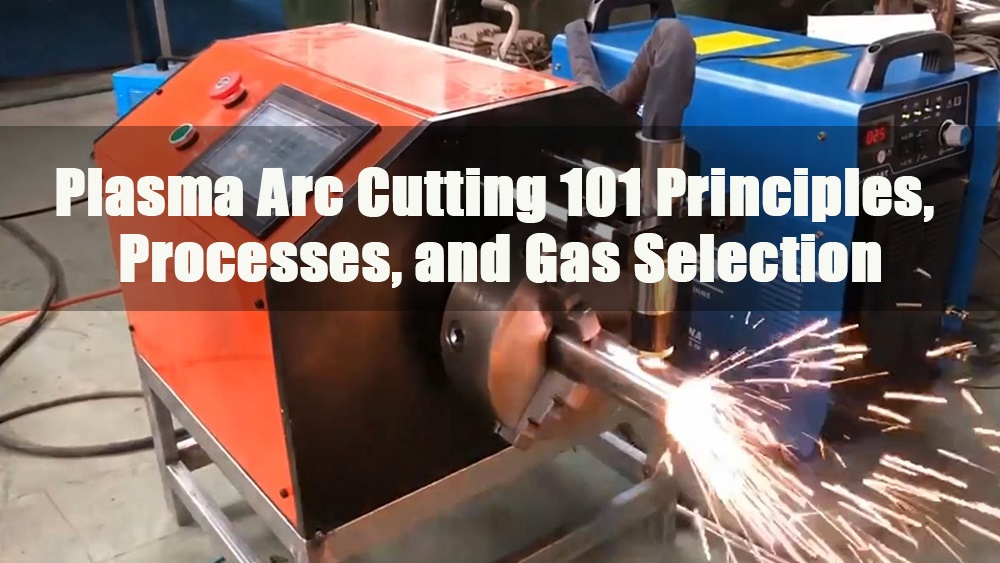
2.0Plasma Arc Cutting (PAC)
Plasma Arc Cutting Introduction:
Plasma arc cutting works by directing a high-temperature plasma jet onto the workpiece, melting the material and blowing it away to achieve a cut.
- Suitable for cutting stainless steel, aluminum, and non-ferrous metals.
- Plasma gas velocity is extremely high; arc temperatures can reach up to 20,000°C.
- Cutting generates intense noise; underwater cutting can reduce sound levels.
- Common gases include nitrogen, argon, helium, and their mixtures.
2.1Plasma Cutting:
Plasma cutting does not require preheating. The high-temperature arc melts the material instantly, while a high-speed gas jet removes the molten metal.
- Oxidizing air plasma: Involves oxygen in the process, increasing cutting speed.
- Gas selection: Air, nitrogen, argon-hydrogen, and nitrogen-hydrogen mixtures are chosen based on the material.
- Applications: Suitable for stainless steel, aluminum, and thin carbon steel sheets.
- Shielding gases: Used as needed depending on the application.
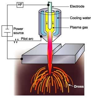
2.2Plasma Arc Cutting System:
A complete plasma cutting system typically includes:
- Power source: DC output, typically 50–350A with an open-circuit voltage around 80V.
- High-frequency arc starter.
- Water cooling unit.
- Plasma torch.
- Plasma gas supply and optional external shielding gas.
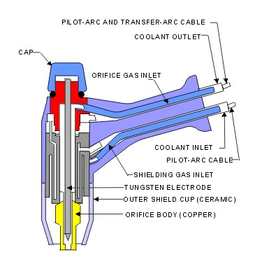
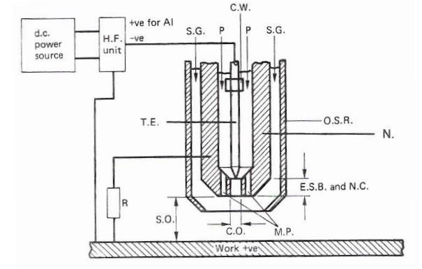
2.3Component Parts of a Plasma Arc Torch:
Key torch components include:
- C.W.: Cooling water for the nozzle and electrode
- P: Plasma gas; varies depending on material type
- S.G.: Auxiliary shielding gas
- T.E.: Tungsten electrode
- O.S.R.: Outer shielding ceramic; prevents double arcing
- R: Resistance; limits pilot arc current
- E.S.B.: Electrode setback distance
- N.C.: Nozzle construction
- C.O.: Orifice construction; improves gas velocity
- S.O.: Stand-off distance; approximately 6 mm
- M.P.: Multi-port design; shapes the plasma arc
- H.P.: High-frequency discharge; initiates arc ignition
- N: Copper nozzle
2.4Real-world Applications
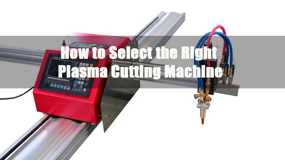
- A Plasma Pipe Cutting Machine handles φ20–φ219 mm round pipe, enabling single-cycle intersection-line and hole cutting with portable CNC systems.
- A full-size CNC Plasma & Flame Cutting Machine (gantry type) supports sheet sizes 0.8–160 mm, offering automated kerf compensation and dual-drive gantry for precision.
2.5Cutting Speeds for Plasma Arc Cutting:
Cutting speed directly affects quality and efficiency.
- Too slow: Results in a wider kerf and increased slag buildup.
- Too fast: May lead to incomplete cuts and excessive spatter.
Cutting speed should be matched with current, nozzle size, and material thickness.
CNC systems allow precise speed control for consistent results.
| Material | Thickness mm |
Current amps |
Cutting speed Mm/min |
Gas |
| Aluminium | 1.5 5.0 12.0 25.0 |
40 50 400 400 |
1200 1500 3750 1250 |
A/H₂ A/H₂ A/H₂ A/H₂ |
| Stainless steel 18/8 |
2 5 12 25 |
50 100 380 500 |
1600 2000 1500 625 |
A/H₂ A/H₂ A/H₂ A/H₂ |
2.6Generic Settings for Plasma Arc Cutting:
Recommended general settings include:
- Align the electrode and nozzle to maintain arc stability.
- Maintain a standoff distance of approximately 6 mm between the nozzle and the workpiece.
- Select gas type and pressure based on the material being cut.
- Control arc intensity and avoid double-arc conditions.
Mode Switch Functions:
Expanded Metal Mode: Automatically reinitiates the pilot arc as needed when cutting expanded metal.
Cutting Mode (Plate/Sheet Metal): Used for solid plates or sheets; extends consumable life.
Gouging Mode / Non-Transferred Arc: Intended for gouging tasks or applications requiring a non-transferred arc.
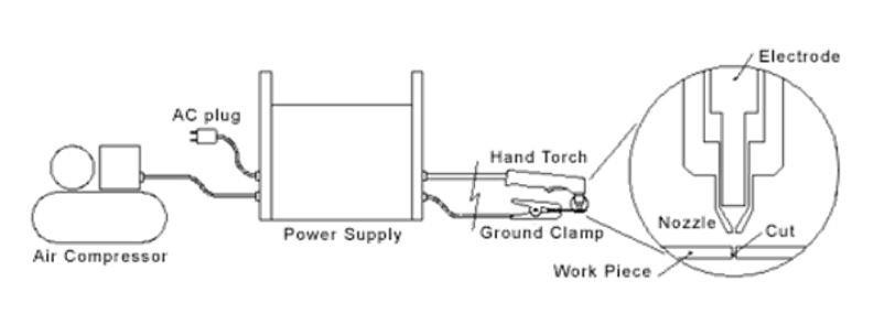
3.0Operation of Hand Torch for Plasma Arc Cutting
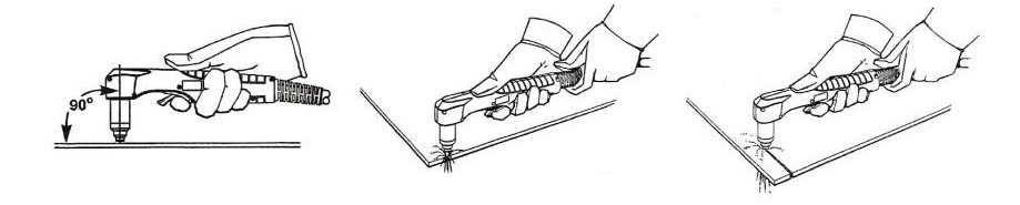
3.1Hand Torch Operation: Edge Start
Edge start is the most common method used in manual plasma cutting.
- Step 1: Torch Positioning: Hold the torch nozzle in direct contact with or close to the edge of the workpiece.
- Step 2: Arc Initiation: Initiate the arc and pause briefly to allow full penetration through the edge.
- Step 3: Cutting: Once the arc has pierced through, begin moving along the desired cut path. Maintain a consistent speed and angle. The torch should be held perpendicular or slightly tilted back (10–15°) to assist with slag ejection.
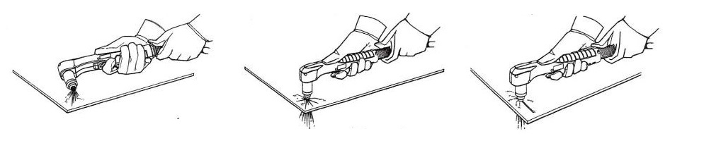
3.2Hand Torch Operation: Piercing Technique
Piercing is a critical operation when cutting medium to thick plates.
- Thin materials (<2 mm): Start the arc at a 15–30° angle, then rotate to a vertical position.
- Thick materials (≥2 mm): Maintain a standoff distance of at least 12 mm during arc initiation; lower to cutting height after penetration.
Caution: Metal spatter during piercing may damage the nozzle and electrode—use proper distance and angle control.
Piercing Procedure:
Step 1: Torch Positioning: Hold the torch approximately 1/8 inch (3 mm) above the workpiece surface.
Step 2: Torch Firing and Angle Adjustment: Fire the torch while holding it at a slight angle, then rotate to upright as the arc stabilizes.
Step 3: Piercing and Cutting: When sparks exit from the bottom, the arc has fully pierced the material. Continue with the cut immediately after.
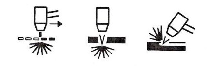
3.3Hand Torch Operation: Gouging Technique
Gouging is commonly used for weld removal or backside weld preparation.
- Use dedicated gouging nozzles and shield attachments.
- Maintain an arc initiation distance of approximately 12 mm.
- Tilt the torch 20–40° and perform steady side-to-side motion during travel to control groove width and depth.
- A protective heat shield is recommended to safeguard the torch and the surrounding area.
Plasma Gouging Procedure:
Step 1: Torch Positioning: Hold the torch roughly 1.5 mm from the workpiece surface.
Step 2: Pilot Arc and Arc Transfer: Position the torch at a 45° angle and trigger the arc. Once stable, the arc will transfer to the workpiece.
Step 3: Gouging Operation: Maintain the 45° angle throughout the process. Move the torch in the travel direction with a steady feed to form the gouge.
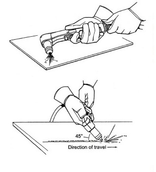
Note: A heat shield can be used to provide additional protection for the operator’s hand and torch components during gouging operations.
3.4Plasma Process Techniques Tips
To improve cutting quality and overall efficiency, the following best practices are recommended:
- Use of guides and rollers: Employ torch guides or roller attachments to maintain a vertical orientation and consistent travel speed.
- Maintain proper standoff distance: Keep the nozzle at the correct distance from the workpiece to avoid bevel defects and ensure cut consistency.
- Control kerf width and directionality: Understand the kerf (cut width) and its directional bias; set CNC compensation accordingly for accurate part dimensions.
- Cutting direction matters: The direction of travel (clockwise or counterclockwise) affects cut edge squareness. Choose the direction based on the desired contour and final edge quality.
Interested in integrated cutting solutions?
Explore our advanced Plasma Pipe Cutting Machine and CNC Plasma & Flame Cutting Machine to streamline pipe and plate fabrication workflows—contact us for detailed datasheets and pricing.