1.0Torch Components & Function
1.1The Plasma Torch Components Overview
The plasma torch is a precision tool designed for high-temperature cutting applications. It consists of several critical components that work together to generate and control the plasma arc:
- Drag Shield – Protects the nozzle and maintains optimal stand-off distance from the workpiece during drag cutting operations.
- Retaining Cup – Holds the nozzle and electrode securely in place, ensuring proper alignment and electrical contact.
- Nozzle – Focuses the plasma arc and directs the high-velocity jet toward the material being cut, playing a key role in cut quality.
- Electrode – Conducts electricity to create the plasma arc and withstands extreme temperatures during operation.
- Swirling Ring – Introduces a swirling motion to the plasma gas, stabilizing the arc and enhancing precision.
- Torch Body – Houses all internal components and provides ergonomic handling, cooling, and connection to the power and gas supply systems.
Together, these elements form a reliable and efficient plasma torch system capable of delivering clean, precise cuts across a variety of conductive materials.
2.0Arc Starting Methods in Plasma Cutting
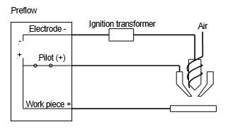
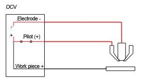
Plasma cutting requires ionization of air to initiate electrical conductivity and sustain the plasma arc. Since air is naturally a good insulator, specialized starting methods are necessary. One of the most common is the High-Frequency Start, which follows a three-step process:
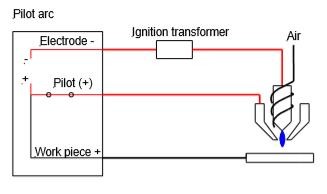
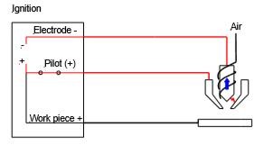
2.1Pilot Arc Initiation
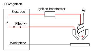
A high-voltage, high-frequency spark is generated within the torch head to briefly ionize the air. This ionization makes the air conductive, allowing a pilot arc to form between the electrode and the nozzle, both located inside the torch head.
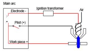
2.2Plasma Jet Formation
As the ionized air (now plasma) is forced through the nozzle, it is expelled toward the workpiece. This extends the arc from the torch to the workpiece, establishing a current path from the electrode to the metal surface.
2.3Transfer of Arc to the Workpiece
Once the system detects that current is flowing to the workpiece, it disengages the electrical connection between the electrode and the nozzle. The main cutting arc is now transferred outside the nozzle, from the electrode directly to the material, minimizing wear on the nozzle.
Note: While this method simplifies arc initiation and allows for non-contact starts, it comes with drawbacks. The nozzle is consumed during each arc start, so its lifespan is determined by the number of arc initiations, not the cutting duration.
Electromagnetic Interference (EMI) Warning
High-frequency arc starting can produce electromagnetic interference that may disrupt sensitive equipment such as PLCs, CNC controllers, or PCs. In environments where such equipment is present, it is advisable to consider alternative arc starting methods (e.g., lift arc or blowback start) to avoid operational issues.
3.0Lift Arc Method (Blowback Start)
The lift arc, or blowback start, is a non-high-frequency method used to initiate a plasma arc without generating electromagnetic interference, making it ideal for use near sensitive electronic equipment.
Working Principle:
This method involves a DC positive nozzle and a DC negative electrode housed inside the torch. The arc initiation follows a four-step mechanical and electrical sequence:
3.1Initial Contact
At rest, the electrode is in physical contact with the nozzle, and no arc is present. When the operator pulls the trigger, DC current begins to flow between the electrode and the nozzle.
3.2Blowback Separation
Compressed air (plasma gas) begins to flow into the torch. As pressure builds, it mechanically pushes the electrode away from the nozzle, creating a small gap. This sudden separation produces an electric spark, which ionizes the air, initiating the plasma formation.
3.3Pilot Arc Formation
As the electrode retracts, a stable pilot arc is established between the electrode and the nozzle inside the torch.
3.4Arc Transfer to Workpiece
When the torch is brought near the workpiece, the electrical potential difference between the nozzle and the workpiece causes the pilot arc to transfer externally, forming the cutting arc from the electrode to the material surface.
3.5Advantages of the Blowback Start Method
- No high-frequency interference — safe for use near CNC machines, PCs, and PLCs.
- Longer nozzle and electrode life due to reduced arc wear.
- Mechanically simple and reliable ignition system.
This starting method is widely used in modern handheld and mechanized plasma systems where reliability and EMI-free operation are essential.
4.0Pilot Arc Control Methods
In plasma cutting systems, the pilot arc plays a key role in initiating the main cutting arc. Depending on the power source design, pilot arc behavior can be either continuous or controlled dynamically.
4.1Continuous Pilot Arc
Some power sources keep the pilot arc active throughout the entire cutting process, even after the cutting arc has been transferred to the workpiece.
Advantage:
Ideal for cutting expanded metal or materials with gaps. As the arc jumps between segments, the continuous pilot arc ensures seamless cutting without arc loss.
Disadvantage:
Keeping the pilot arc on at all times leads to increased wear of consumables, especially the nozzle and electrode, reducing their service life.
4.2Controlled Pilot Arc (Tip Saver Mode)
More advanced systems allow automatic control of the pilot arc:
The pilot arc is active only during arc initiation.
Once the cutting arc is established, the pilot arc automatically shuts off.
This mode is often referred to as Tip Saver because it reduces consumable wear by deactivating the pilot arc when it’s not needed.
Operator Selection
Modern plasma systems may provide selectable modes:
Expanded Metal Mode: Keeps the pilot arc on continuously — best for perforated or mesh materials.
Tip Saver Mode: Shuts off the pilot arc after transfer — ideal for solid plate cutting to maximize consumable life.
By allowing operators to choose between these control modes, plasma cutting systems can adapt to different cutting tasks, balancing arc stability with consumable efficiency.
5.0Cutting Techniques with a Handheld Plasma Torch
When using a handheld plasma cutter, there are two primary methods for initiating a cut: edge starts and pierce starts. Each method serves a specific purpose depending on the material layout and cut design.
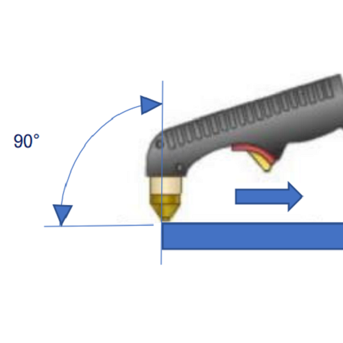
5.1Edge Start
The edge start is the preferred method whenever possible, as it reduces stress on consumables and ensures cleaner cuts.
- How to perform:
- Position the torch so that the nozzle is centered on the edge of the workpiece.
- Hold the torch at approximately 90° to the surface.
- Start the arc and begin moving steadily along the desired cut line.
- Tips for accuracy:
- Use a straightedge guide, such as a metal bar or angle iron, to help maintain a straight path.
- Instead of a drag shield, consider using a roller guideto ensure consistent standoff distance.
Edge starts are ideal for cleaner starts and extending consumable life.

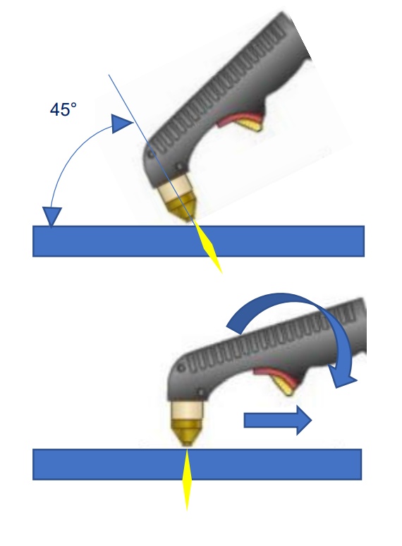
5.2Pierce Start
When an edge start is not possible, such as when cutting holes or starting within a sheet, use the pierce start method. This technique requires more caution and precision.
- How to perform:
- Begin by angling the torch slightly(approximately 45°) toward the workpiece to deflect molten metal away from the tip.
- Initiate the arc and allow the plasma to pierce through the material.
- Once pierced, rotate the torch to a vertical position (90°)and proceed with the cut.
- Piercing considerations:
- Thicker materials require more time to pierce; be patient to avoid damage to the torch.
- The pierce point will create a larger hole(blowout) than the standard kerf.
- Always pierce in the scrap area of the material, not directly on the intended cut line.
⚠️ Piercing generates more spatter and wears consumables faster. Edge starting is recommended whenever feasible.
6.0Plasma Arc Gouging Technique
Plasma arc gouging is a versatile technique used for removing metal rather than slicing through it. It is commonly applied in weld removal, edge preparation, and correction of weld discontinuities, and can be performed in all positions.
6.1Gouging Setup
When switching from cutting to gouging, it is typically necessary to replace some consumables in the torch. A gouging tip should be used — it features a larger orifice (3–4 times wider) than a standard cutting tip, designed to push the arc outward and remove more material.
You can use:
A shield cup body combined with either a gouging shield cap or a shield deflector, or
A single-piece shield cup specifically designed for gouging.
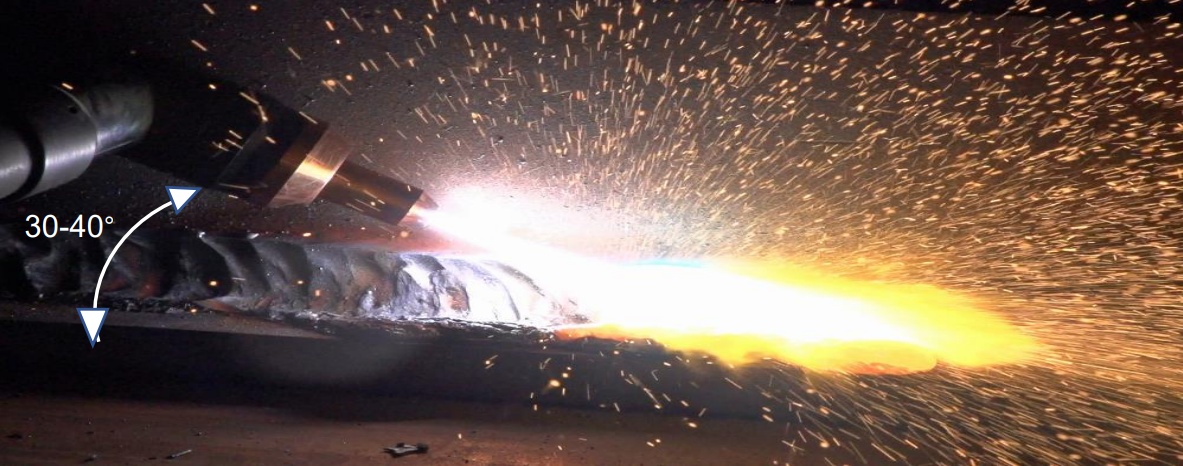
6.2Proper Gouging Technique
- Torch Angle: Hold the torch at an angle of 30°–40°to the base metal.
- Gouging Depth: Controlled by the torch angle and travel speed.
- Material Removal: Avoid excessive removal in a single pass. Use multiple controlled passes to achieve the desired depth and width.
- Parameter Control:
- Current output
- Travel speed
- Standoff distance
- Lead angle
- Tip size
All of these factors will influence the profile and depth of the gouge.
6.3Applications
- Removing old, imperfect, or defective welds
- Preparing U-grooves for welding
- Correcting surface discontinuities
- Creating weld access or relief areas
6.4Limitations of Plasma Cutting
While plasma gouging is effective and precise, oxy-acetylene cutting may still be preferred in certain scenarios, especially when:
- Cutting steel sections thicker than 25 mm (1 inch)
- Compressed air or electricity is unavailable
- Faster throughput is required on thick materials
Oxy-fuel torches operate independently of electrical power and can outperform plasma in heavy-duty steel applications under specific conditions.
7.0Plasma Gas Requirements and Air Supply Guidelines for Cutting Systems
7.1Plasma Gas in Arc Cutting
Plasma arc cutting requires carefully selected gases to ensure arc stability, cut quality, and equipment longevity. The ideal plasma gas must meet the following criteria:
- High Ionization Potential– Enables the gas to become electrically conductive under high voltage.
- High Thermal Conductivity– Efficiently transfers heat energy to the workpiece for faster, cleaner cuts.
- High Atomic Weight– Provides sufficient momentum to blow molten metal out of the kerf, ensuring effective material separation.
7.2Common Plasma Gas: Compressed Air
Compressed air is widely used due to its cost-effectiveness and availability. Composed of approximately 80% nitrogen, it meets the basic requirements for ionization and density.
Key Considerations:
- Moisture and Oil Removal: Compressed air must be clean and dry. Use line filters, dryers, or separators to remove water and oil vapors, which can damage the torch or cause erratic cutting.
- Control Air Preference: The best source of compressed air is typically the system’s control air, which is already filtered.
7.3Air Supply Requirements (Typical Guidelines)
| Plasma Unit Type | Steel Cutting Capacity | Air Flow Rate | Air Pressure |
| Small Unit | Up to 10 mm (3/8″) | 113–142 l/min (4–5 SCFM) | 6–8 bar (90–120 PSI) |
| Medium Unit | 16–19 mm (5/8″–3/4″) | ~170 l/min (6 SCFM) | 6–8 bar (90–120 PSI) |
| Heavy-Duty Unit | 19–24 mm (3/4″–1″) | 198–227 l/min (7–8 SCFM) | 6–8 bar (90–120 PSI) |
⚙️ Tip: If you frequently cut thick materials or use the system heavily, choose a compressor with 1.5–2 times the plasma system’s minimum requirement for consistent performance.
7.4Gas Line and Hose Sizing
To maintain adequate pressure and volume:
- Use minimum 10 mm (3/8″)inside diameter (ID) hoses or piping.
- For lines longer than 12 m (40 ft), increase to a minimum 12 mm (1/2″) ID.
Inadequately sized gas lines can result in pressure drops, poor arc quality, and reduced cutting performance.
7.5Filtration and Torch Protection
While many plasma systems include built-in regulators and air filters, additional external filtration is strongly recommended.
- Why? Moisture and contaminants like oil or particulates can lead to internal arcing in the torch, potentially damaging consumables or the torch body itself.
- Good Practice: Install water separators, particulate filters, and coalescing filters in the air supply line for optimal torch protection.
By using clean, properly pressurized gas with appropriate delivery infrastructure, you can ensure longer torch life, better cut quality, and safer operation of your plasma cutting system.