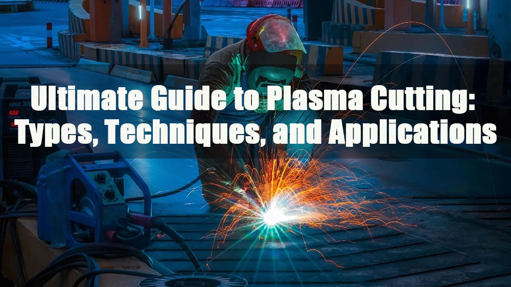
1.0What is Plasma Cutting Technology?
1.1Technology Origins and Development:
During World War II, U.S. factories achieved significant industrial innovations, greatly increasing the production efficiency of aircraft and military equipment.
Welding Technology: To improve the cutting and welding efficiency of aircraft parts, engineers adopted a new welding technique—Tungsten Inert Gas (TIG) or Gas Tungsten Arc Welding (GTAW). This method utilized an electric arc to activate inert gases, forming a conductive protective layer that prevented oxidation during welding, enhancing the quality of welds and structural strength.
1.2The Birth of Plasma Cutting:
Early 1960s: Engineers further innovated on TIG welding technology:
Increased gas flow: and guided the arc through a constricted nozzle.
Formation of Plasma: This high-temperature, high-speed ionized gas could melt metal and, through high-speed airflow, blow away the molten metal, enabling fast cutting.
This new method was called “Plasma Arc Cutting,” which greatly improved cutting speed, precision, and material adaptability, allowing easy cutting of various conductive metals.
2.0What is Plasma?
Plasma State: When gases are heated to extremely high temperatures, molecules begin to break apart, and electrons are ejected from atoms, forming a fourth state of matter—plasma.
Plasma Composition: Plasma consists of a positively charged atomic nucleus (protons and neutrons) and negatively charged electrons.
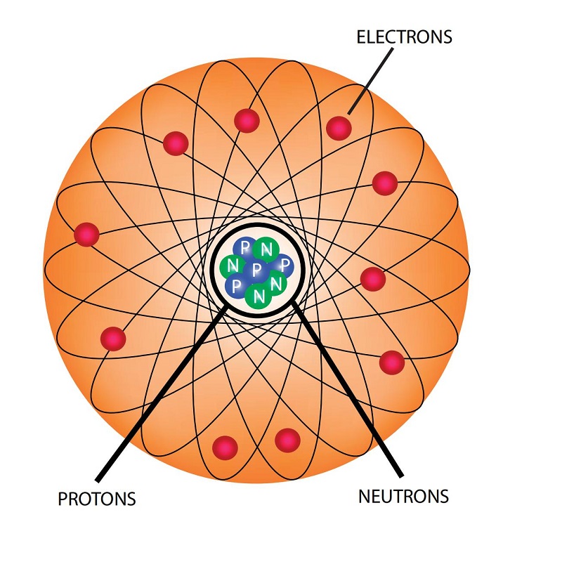
In plasma, electrons are separated from the atomic nucleus, forming freely moving electrons (negative charge) and ions (positive charge).
Energy Release: High-speed collisions between electrons and ions release large amounts of energy, which is why plasma has such powerful cutting capabilities.
🔋 Natural Examples of Plasma: Lightning
💡 Applications of “Cold Plasma”: Neon lights, fluorescent lights, plasma TVs (though they cannot cut metals, they have widespread practical applications).
2.1Plasma State of Matter
Four States of Matter:
In our daily life, we commonly encounter three states of matter: solid, liquid, and gas. Plasma cutting involves the fourth state—plasma.
Using water as an example to explain molecular behavior in different states:
- Solid (Water → Ice): Molecules are tightly packed, with minimal movement, and have a fixed shape.
- Liquid (Water): Molecules are connected but can move slowly, with a variable shape but fixed volume.
- Gas (Water Vapor): Molecules move freely at high speeds, with no fixed volume or shape.
- Plasma State:
When gas is further heated, its molecules gain more energy, causing electrons to escape from the atoms. This forms a group of particles with positive and negative charges, and this highly ionized substance is plasma. Plasma has both gas-like flowability and the ability to conduct electricity, making it ideal for high-temperature processing and cutting.
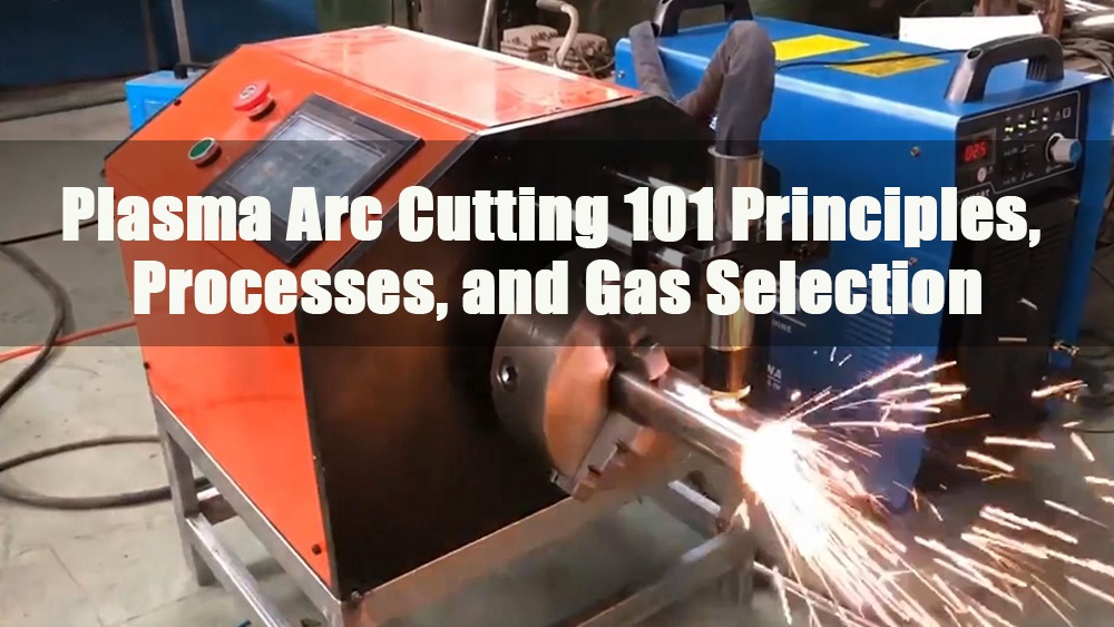
2.2Plasma Cutting Process Principle
- Formation Method: An electric arc is created between the electrode and the workpiece. After passing through a fine copper nozzle, the arc is constricted, forming a high-temperature, high-pressure plasma flow.
- Temperature and Speed: The temperature of plasma can reach up to 15,000°C, and the jet speed is close to the speed of sound.
- Cutting Process:
- High-temperature electric arc melts the metal.
- High-speed airflow blows the molten metal away from the cutting gap.
- This allows for precise and fast cutting.
- Process Features: Deep melting, clean edges, and high cutting speed.
2.3Plasma Cutting vs. Oxygen-Fuel Cutting
| Comparison Item | Plasma Cutting | Oxygen-Fuel Cutting |
| Principle | High-temperature plasma arc melts metal + airflow blows away molten metal | Oxygen oxidizes the metal + exothermic melting |
| Cutting Objects | All conductive metals (including aluminum, stainless steel, etc.) | Mainly limited to carbon steel |
| Metal Surface Requirements | Can cut metals with protective oxide layers | Not suitable for stainless steel, aluminum, etc. |
| Heat Affected Zone | Relatively small, clean cut edges | Large heat-affected zone, significant oxidation of the cut edges |
3.0Plasma Cutting Gas Selection and Material Compatibility
Modern plasma cutting systems use various gas combinations depending on the material type and cutting requirements. Choosing the right gas not only affects cutting quality and speed but also impacts electrode life and the feasibility of post-weld treatment.
3.1Compressed Air
- Wide Application: Suitable for carbon steel, stainless steel, aluminum, and most metals.
- Common Usage: Often used in handheld plasma cutters, easy to source, and low cost.
- Chemical Reaction: About 20% oxygen in air reacts with carbon steel to enhance cutting speed and reduce slag.
- Drawbacks:
- Nitrogen content can form a nitrided layer on the steel surface, making it very hard and unsuitable for welding.
- Stainless steel cutting may leave a brown oxide layer, requiring pre-treatment before welding.
3.2Oxygen
- System Compatibility: Only used in systems designed to support oxygen.
- Performance: Performs best on carbon steel, providing the highest cutting speed, best cut quality, and weldability.
- Machining: Cuts can be directly drilled, tapped, or machined.
- Limitations: Not suitable for aluminum and stainless steel.
3.3Nitrogen
- Slower Cutting Speed: Cannot react exothermically with metals, resulting in slower cutting speeds.
- Nitrided Layer: Forms a very hard nitrided layer on carbon steel, leaving heavy slag residues.
- Stainless Steel or Underwater Cutting: Helps reduce oxidation reactions and protects the cut edges.
- Extended Consumable Life: When combined with high-purity nitrogen and suitable tungsten electrodes, it can significantly extend consumable life.
- Common in Older Models: Often used in older plasma cutting machines.
3.45% Hydrogen / 95% Nitrogen (H5/N95)
- Primary Use: For high-quality cutting of stainless steel under 6mm.
- Equipment Requirements: Requires specific consumables and precise flow/pressure control.
- Advantages: Provides excellent edge quality but is not suitable for thicker materials.
3.535% Hydrogen / 65% Argon (H35/Ar65)
- Special Equipment: Requires high-pressure cylinders for gas mixing.
- Application: Commonly used for cutting aluminum or stainless steel above 9.5mm.
- Other Uses: Suitable for plasma gouging, replacing carbon arc gouging.
- Limitations: May produce heavy re-melt slag on thin stainless steel.
Safety Warning:
Do not use oxygen or hydrogen mixtures in unauthorized systems, as this could lead to fire or explosion risks.
Always follow the equipment manufacturer’s gas compatibility and operating guidelines.
4.0Recommended Compressed Air System Configuration for Plasma Cutting
A high-quality compressed air supply system is essential to ensure the stability and cutting quality of plasma cutting. Below are key dimensions to consider when designing and selecting your system:
4.1Basic Selection Questions:
| Project Issue | Recommendation |
| Maximum working pressure for plasma cutter? | Should match equipment specifications, typically in Bar or PSI. |
| Maximum airflow required for plasma cutter (CFM)? | Choose a compressor based on the required airflow. |
| Portable or stationary setup? | Select a model based on the work environment—portable for field use or fixed for factory settings. |
| Motor or diesel drive? | Electric motor preferred for factories, diesel for outdoor operations. |
| Receiver tank capacity? | Should match airflow/peak load to ensure stable air supply. |
| Use of three-phase power? | Three-phase compressors are more efficient and provide more stable output. |
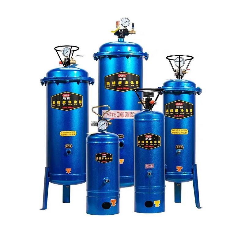
4.2Accessories and Air Source Purification Recommendations:
The quality of compressed air directly affects cutting stability and consumable life. The following components are recommended for the system:
| Accessory Type | Function |
| Air Hose | Choose the appropriate diameter and length to minimize pressure loss. |
| Filters | Filter moisture, oil mist, and impurities to extend electrode/nozzle life. |
| Dryers | Use refrigerated dryers to control dew point and prevent arc instability. |
| Regulators | Precisely control working air pressure to maintain stable cutting. |
| Quick Couplings | High-flow couplings for large-capacity cutting equipment, ensure proper matching sizes. |
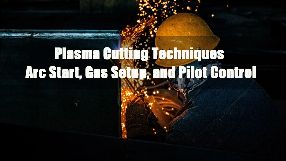
5.0Plasma Pilot Arc Ignition Methods
5.1High-Frequency Arc Ignition (Traditional Method)
- Principle: High-frequency, high-voltage sparks create a spark gap, allowing air to become conductive and generating the pilot arc.
- Drawbacks:
- Can interfere with nearby electronic devices (e.g., CNC control systems, computers, etc.).
- Risk of electric shock.
- Spark gap is prone to wear and difficult to repair.
- Emits radio frequency (RF) signals, which can be a safety concern in industrial settings.
5.2HF-Free Arc Ignition (Modern Mainstream Method)
To accommodate CNC systems and sensitive electronic environments, modern plasma systems commonly use HF-free (High-Frequency-Free) ignition technology:
Capacitor Discharge (SCR Ignition)
Uses a silicon-controlled rectifier (SCR) to release high-energy short pulses from the capacitor into the main circuit, creating an initial spark to trigger the arc.
Blow-Apart Arc Ignition
The electrode and nozzle inside the torch initially make contact. When the trigger switch is activated, gas flow separates the two, creating a spark and establishing the pilot arc.
Spring-Loaded Arc Ignition
When the torch is pressed against the workpiece, the electrode and nozzle are short-circuited. Releasing the pressure causes the two to separate, forming the arc.
Suitable for contact or close-cutting applications.
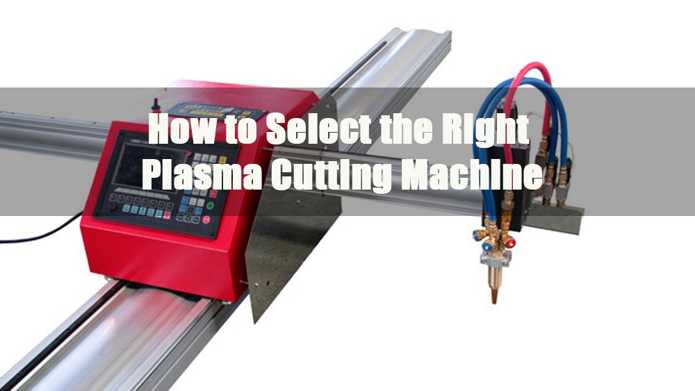
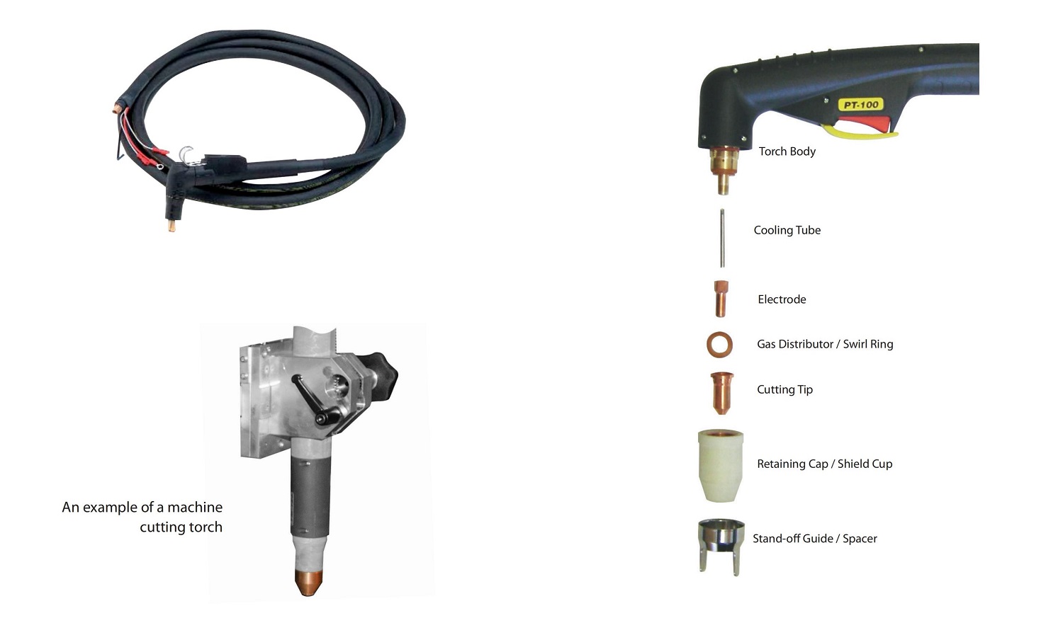
6.0Components of a Plasma Cutting System
Plasma cutting is an efficient metal processing technique suitable for both thin and thick materials.
Handheld Torch: Capable of cutting steel plates up to approximately 50mm thick.
Automated Water-Cooled Torch (with CNC System): Capable of cutting steel plates up to 150mm thick.
Traditionally, plasma cutting is limited to conductive materials, but modern technology can now cut non-conductive materials like glass and plastic under specific conditions (e.g., closed ignition systems).
6.1Plasma Cutting Power Source
The power source required for the plasma arc is a direct current (DC) output with a voltage-drooping characteristic and high open-circuit voltage.
Technical Parameters:
- Working Voltage: Typically between 90-130 VDC.
- Open-Circuit Voltage (Starting Voltage): Can be as high as 330 VDC.
Common Power Source Types:
- Transformer Rectifier Type: Traditional, offers good stability.
- Inverter Type Power Source: Compact, high efficiency, suitable for precision control or portable applications.
6.2Arc Ignition and Polarity Configuration
- Pilot Arc: When cutting begins, a pilot arc is initially generated inside the torch between the electrode and nozzle.
- Transferred Arc Mode: The arc is transferred to the workpiece to begin the actual cutting.
- Electrode Polarity: Negative (-)
- Workpiece Polarity: Positive (+)
This configuration concentrates approximately 2/3 of the arc energy on the workpiece, improving cutting efficiency and penetration.
6.3Gas Composition and Electrode Matching
Common Plasma Gases and Their Effects
| Gas Type | Characteristics and Applications | Electrode Material |
| Air / Oxygen | Highly oxidizing, commonly used for cutting carbon steel and other conventional materials | Copper + Lanthanum/Hafnium Insert (Hf) |
| Argon / Argon-Hydrogen | Inert gas, suitable for cutting stainless steel, aluminum alloys, etc. | Tungsten (W) |
| Nitrogen | Stable, suitable for thin sheet or non-ferrous alloys | Tungsten (W) |
6.4Importance of Gas Flow Rate
The correct gas flow rate must be set based on the current and nozzle size.
If the gas flow is too low and the current is too high, a double arcing phenomenon may occur:
The arc transfers from the electrode to the nozzle, and then from the nozzle to the workpiece, causing rapid consumable wear, nozzle melting, and electrode damage.
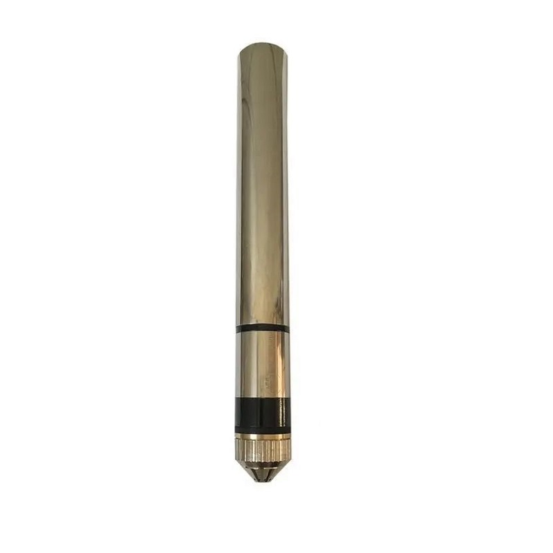
6.5Plasma Torch Overview
The torch is the core component of the plasma cutting system, responsible for conducting the arc and directing the gas flow.
Types
- Air-Cooled: Lightweight and suitable for low to medium power applications.
- Water-Cooled: Ideal for high-load, long-duration cutting, offering good thermal stability.
Modern Torches Compared to Traditional Models:
- Smaller and lighter.
- Stronger cutting capacity.
- Support multiple arc ignition methods (electrical or mechanical).
Common Issues and Usage Recommendations
| Problem | Cause Analysis | Suggested Operation |
| RF Interference with Electronic Equipment | High-frequency arc ignition causes RF interference | Use HF-free ignition method |
| Rapid Electrode Wear | Incorrect gas selection, unstable arc | Replace with suitable gas and electrode material |
| Severe Nozzle Erosion | Misaligned gas flow rate, too high current settings | Adjust air pressure and nozzle selection |
| Unstable Arc Ignition / Unable to Transfer | Wear or failure of torch internal components | Inspect nozzle, electrode, and ignition circuit |
6.6Standard Handheld Plasma Torch Structure and Safety Design
Torch Connection Components
Standard handheld torches typically include the following connections:
- Power/Gas Interface (e.g., using air as cutting gas)
- Pilot Arc Cable
- Trigger Switch Cable
Safety Protection Circuit
To prevent electric shock during consumable replacement, all plasma torches must include a safety circuit design:
The simplest form is an annular open-circuit loop, which immediately cuts off the circuit when the nozzle retaining cap is removed.
Advanced systems may automatically close the gas valve to prevent accidental operations.
Without a safety circuit, the open-circuit voltage at the torch head can reach up to 350V DC, which is highly dangerous.
Torch Head Structure
The torch head is composed of the following components:
- Electrode
- Swirl Ring: Controls the airflow distribution
- Cutting Tip
- Retaining Cap
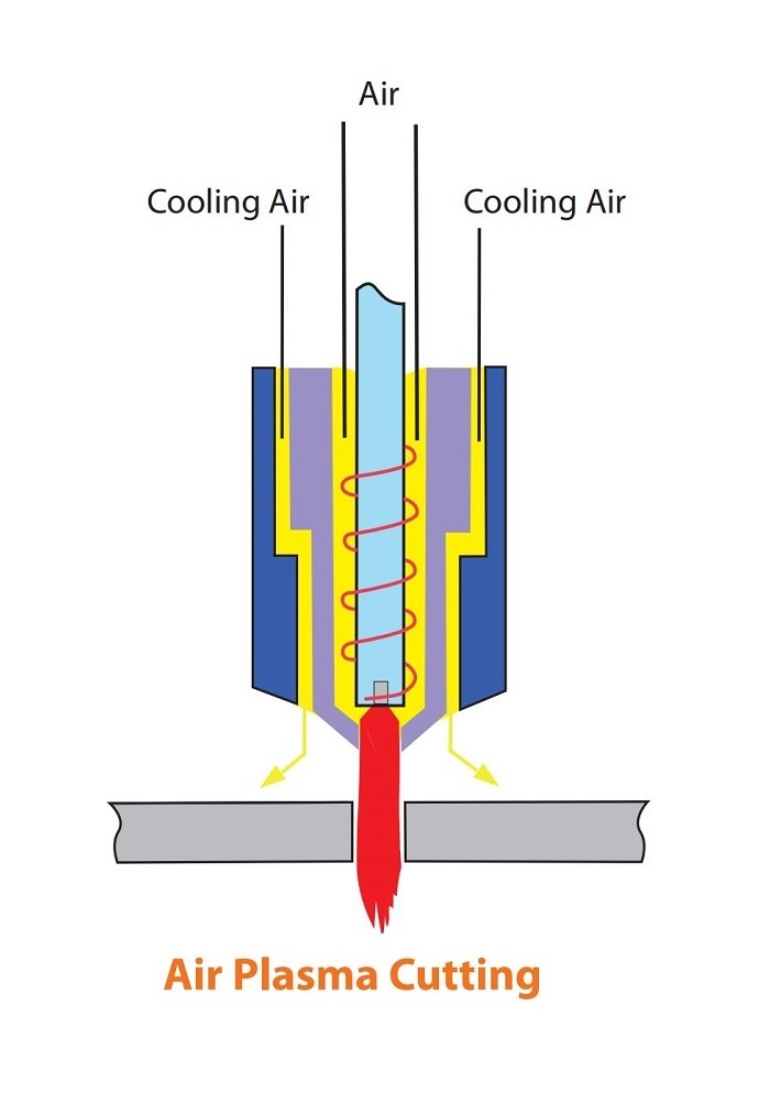
7.0What is Air Plasma Cutting?
7.1Process Features
Air plasma cutting was first used in the 1960s to cut carbon steel and remains one of the most common cutting methods today.
- The oxygen content in the air reacts with the molten metal, generating additional heat (exothermic reaction), which increases cutting speed by approximately 25% compared to nitrogen cutting.
- Drawback: When cutting stainless steel and aluminum, a heavy oxide layer is produced on the surface, requiring post-processing. It is not suitable for applications with strict surface quality requirements.
7.2Consumable Issues
- Oxygen in the air significantly accelerates electrode erosion:
- Using standard tungsten electrodes results in rapid wear within seconds.
- Typically, electrodes made of zirconium, hafnium, or hafnium alloys are used, but their lifespan is still shorter compared to inert gas plasmas.
- Air cooling is also used to maintain system temperature stability.
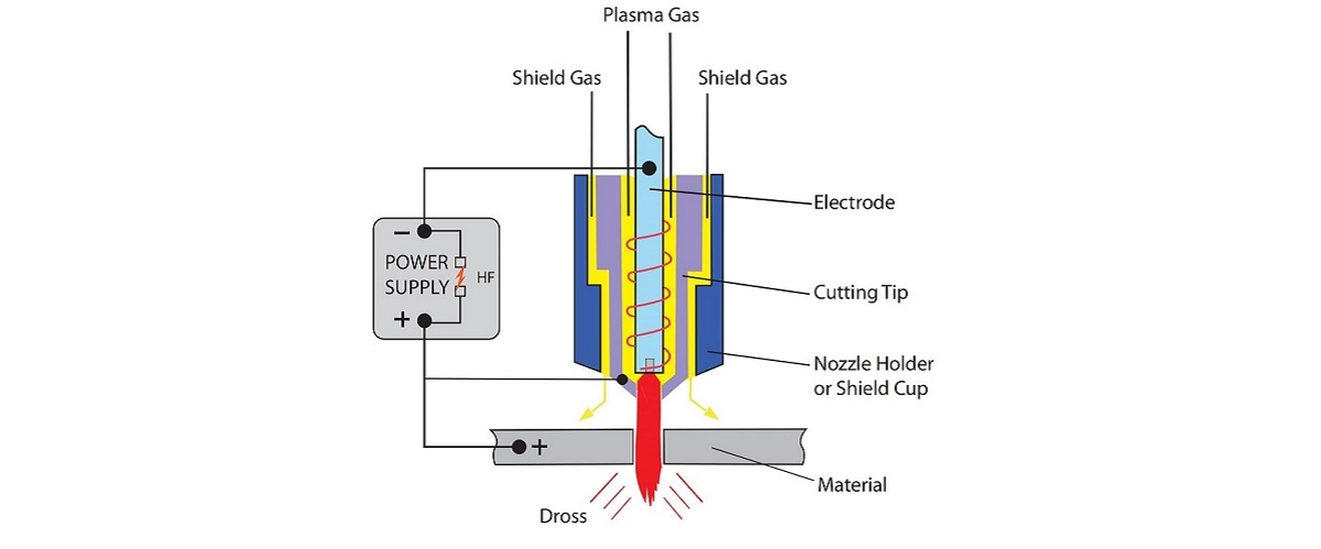
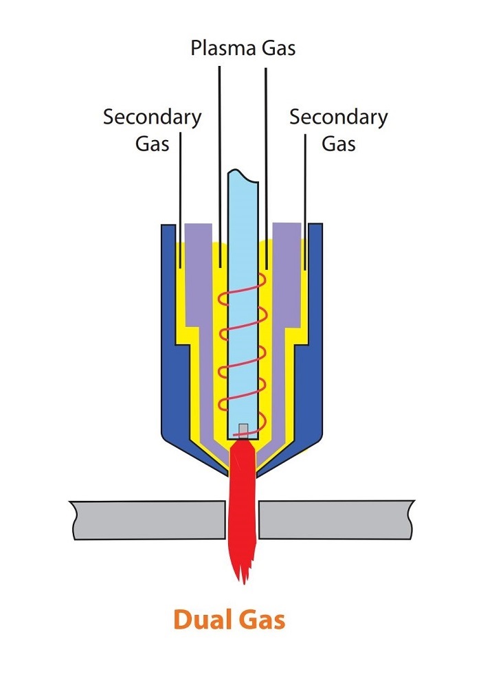
7.3What is Dual Gas Plasma Cutting?
Principle Explanation
Developed by Thermal Dynamics in the early 1960s, dual gas plasma adds a secondary gas (shield gas) surrounding the main nozzle in addition to the primary plasma gas.
Secondary gas purpose:
To narrow the arc and enhance cutting energy density.
To blow away slag, improving cutting cleanliness.
Gas Combination Recommendations
| Material Type | Primary Gas | Secondary Gas (Shield Gas) |
| Carbon Steel | Argon, Argon-Hydrogen Mixture, Nitrogen | Air, Oxygen, Nitrogen |
| Stainless Steel | Nitrogen, Argon-Hydrogen Mixture, CO₂ | Nitrogen |
| Aluminum | Argon-Hydrogen Mixture, Nitrogen/CO₂ | Nitrogen |
Advantages of Dual Gas Cutting
- Retractable Nozzle Design: The nozzle is embedded in a ceramic cup, preventing nozzle short-circuiting and significantly reducing the double arc phenomenon.
- Shield Gas Covers the Cutting Area: This improves cutting quality and speed, while also cooling the nozzle and shield.
Ideal for high-precision, high-quality industrial cutting applications.
7.4High-Precision Plasma Cutting Systems
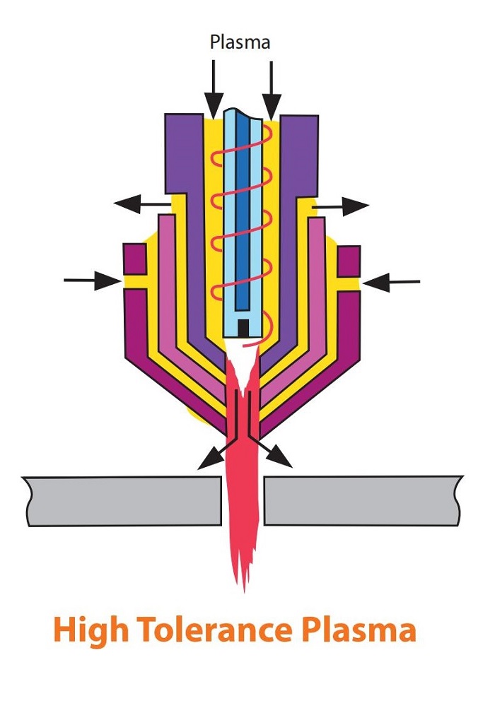
Advantages (Compared to Conventional Plasma)
- Cutting quality: Between conventional plasma and laser cutting.
- Kerf width: Narrower, more suitable for precision machining.
- Heat-affected zone: Smaller, reducing thermal distortion and material tensile stress.
Suitable for integration with CNC and automation systems, improving batch stability.
Disadvantages (Compared to Conventional Plasma and Laser)
- Maximum cutting thickness: Limited, not suitable for very thick plates.
- Cutting speed:
- Slower than conventional plasma cutting.
- Approximately 60–80% the speed of laser cutting.
- Higher equipment cost: Requires a high-precision control system for optimal performance.
7.5Water Injection and Water Shroud Plasma Cutting
Water Injection Plasma Cutting
Water injection plasma cutting involves injecting water radially into the plasma arc. This creates stronger arc constriction than a copper nozzle alone, raising arc temperatures up to 30,000°C—more than twice that of conventional plasma arcs.
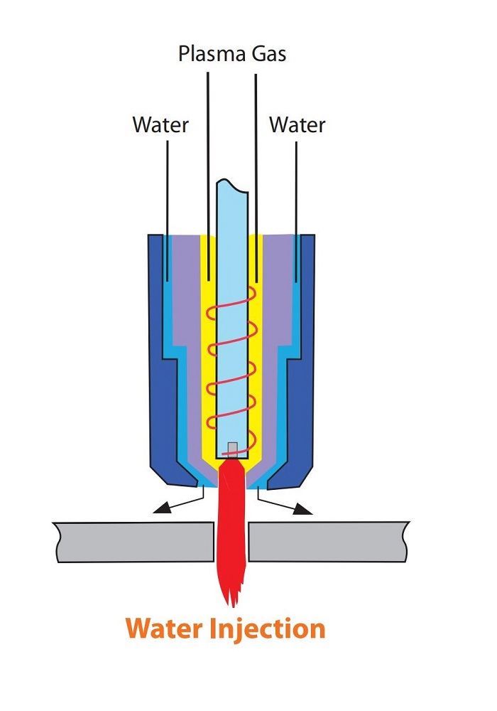
Key characteristics:
- Uses only nitrogen gas for all metals, making the process more economical and easier to operate.
- Nitrogen is highly efficient in transferring heat from the arc to the workpiece. When it dissociates and then recombines at the material surface, it releases additional energy, enhancing cutting performance.
- Less than 10% of the injected water vaporizes. The rest forms a conical spray that:
- Cools the top surface of the workpiece
- Prevents oxide formation
- Cools the torch tip at the area of maximum heat
Advantages over conventional plasma:
- Better cut quality and edge squareness
- Faster cutting speed
- Lower risk of double arcing
- Reduced tip erosion
7.6Water Shroud Plasma Cutting
Water shroud plasma cutting is similar to dual-flow systems, except that water replaces the secondary shielding gas. While it does not improve arc constriction, the cooling effect enhances certain performance aspects.
Characteristics:
- Improves cut appearance and torch tip life
- No significant improvement in cutting speed, squareness, or dross over dual gas systems
- Can be used with a water shroud or with the workpiece submerged 50–75 mm underwater
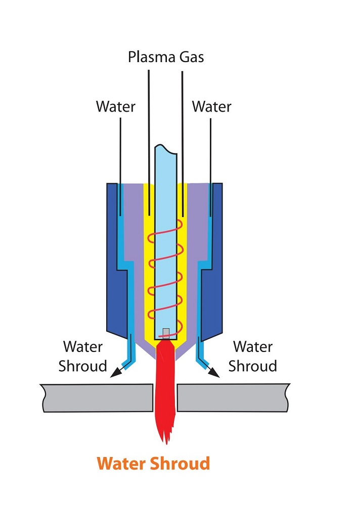
Benefits compared to conventional plasma:
- Reduced fume generation
- Lower noise levels:
- 115 dB for conventional plasma
- 96 dB for water shroud cutting
- 52–85 dB for underwater cutting
- Extended tip life
7.7Overall Summary: Comparison of Plasma Cutting Technologies
| Cutting Method | Cutting Quality | Speed Performance | Heat-Affected Zone | Cost | Special Advantages |
| Conventional Air Plasma | Medium | Fast | Medium | Low | Low cost, versatile |
| Dual Gas Plasma | Medium-High | Fast | Medium | Medium | Clean cuts, improved consumable lifespan |
| Water-Injection Plasma | High | Faster | Small | Medium | Ultra-high temperature, good cooling, clean cuts |
| Water Curtain / Underwater Plasma | Medium | Average | Extremely Small | Low | Low noise, low dust, environmentally friendly |
| High-Precision Plasma | High (close to laser) | Medium-slow | Small | High | High precision, suitable for automation |