- 1.0Material Selection for Stamped Parts
- 2.0Tolerancing Considerations in Metal Stamping
- 3.0Material Chemistry: Avoid Over-Specification
- 4.0Blanking, Trimming, and Perforating Techniques
- 5.0Dimensional Tolerancing for Holes and Features
- 6.0Precision Hole Location Tolerances
- 7.0Tooling Design Guidelines for Metal Stamping
- 8.0Bending and Forming in Press Operations
- 9.0Managing Distortion and Bend Defects
- 10.0Dimensioning and Tolerancing Formed Features
- 11.0Deep Draw Stamping: Design and Process Guidelines
- 12.0Flatness in Metal Stampings
- 13.0Managing Surface Cosmetics in Stamped Parts
- 14.0Handling and Surface Protection
- 15.0Final Thoughts
- 16.0Frequently Asked Questions (FAQ) about Metal Stamping Design
Metal stamping is a cost-effective method for manufacturing durable, high-strength, wear-resistant components with stable and consistent performance.
In this guide, we share comprehensive insights and best practices to help you design stamped parts that maximize manufacturability, repeatability, and material efficiency.
1.0Material Selection for Stamped Parts
Choosing the right sheet or strip metal is critical. Materials vary significantly in price, availability, and performance characteristics. Always consider both mechanical properties and sourcing factors:
- Stock vs. Custom Availability: Standard gauge sizes are commonly stocked and should be prioritized for cost-sensitive or fast-delivery applications.
- Minimum Quantities: Steel mills typically require truckload quantities for custom thicknesses or alloys. If your needs are smaller, sourcing through warehouses may help, but availability will vary.
- Re-rolling Options: Specialty re-rollers can fulfill small quantity requests, but costs increase substantially.
Common Stamping Materials Comparison
| Material Type | Strength | Formability | Relative Cost | Common Applications |
|---|---|---|---|---|
| Mild Steel | Medium | High | Low | Brackets, housings, general parts |
| Stainless Steel | High | Medium | High | Medical tools, appliances |
| Aluminum | Low | Very High | Medium | Enclosures, heat sinks |
| Brass | Medium | High | Medium-High | Electrical contacts, decorative |
2.0Tolerancing Considerations in Metal Stamping
Standard steel grades come in fixed gauge thicknesses with defined tolerances. While tolerances can be tightened, doing so typically drives up cost. When specifying material tolerances:
- Stick to industry-standard gauge thicknesseswhere possible.
- Understand that tight tolerances may limit sourcing options, especially for non-standard material specs.
- Loose tolerances may allow the use of warehouse stock, reducing cost and lead time.
3.0Material Chemistry: Avoid Over-Specification
One of the leading causes of inflated stamping costs is over-specifying the alloy. While many ferrous and non-ferrous alloys exist, only a few are commonly stocked. Specialty alloys must often be custom-melted in large volumes.
- Take advantage of modern continuous casting, which has greatly improved alloy consistency and ductility.
- Consider using warehouse materials whenever your tolerances and application allow it.
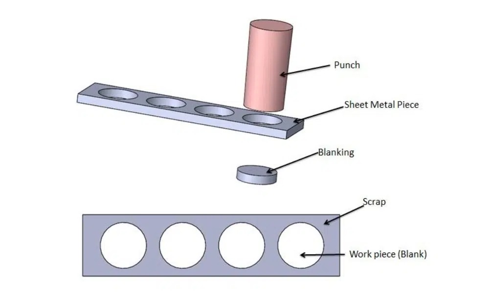
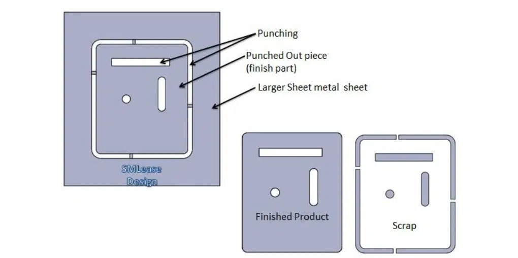
4.0Blanking, Trimming, and Perforating Techniques
Understanding Hole Formation in Stamping
Stamping operations like blanking and perforating involve pushing a tool steel punch through metal into a die. This produces a predictable edge:
- A rolled or radiused top edge is formed as compression begins.
- A burnished, straight wall is created where the material is sheared.
- As stress exceeds material strength, it breaks away, forming a burrow at the bottom.
Managing Burrs in Stamped Parts
Burrs are a natural result of stamping, similar to parting lines in injection molding. Expect burr heights up to 10% of material thickness. These can be:
- Left as-is for non-cosmetic applications.
- Dulled or removed via mass finishing or secondary processes if needed.
5.0Dimensional Tolerancing for Holes and Features
Punch and die clearances (typically 8–10% of material thickness per side) cause:
- Inside features(e.g., holes) taper wider at the top.
- Outside features(e.g., tabs) taper narrower at the bottom.
Designers should:
- Dimension holes at the smallest/sheared diameter.
- Dimension outside features at the largest/sheared portion.
- Use shaving operations for straight edges, if necessary, at added cost.
Typical Tolerances by Material
| Material Type | Common Gauge Tolerance | Piercing Tolerance Capability |
|---|---|---|
| Mild Steel | ±0.005″ | ±0.002″ |
| Stainless Steel | ±0.003″ | ±0.0025″ |
| Aluminum | ±0.004″ | ±0.002″ |
| High Strength Alloys | ±0.006″ | ±0.003″ |
6.0Precision Hole Location Tolerances
- Same-plane piercing is extremely accurate: ±.002″ between holes is common.
- If holes are closer than 1.5× material thickness, or on different planes, tolerances must be loosened to account for springback and bend variation.
- Tightly spaced holes may require separate operations to maintain accuracy.
| Material Type | Common Gauge Tolerance | Piercing Tolerance Capability |
| Mild Steel | ±0.005″ | ±0.002″ |
| Stainless Steel | ±0.003″ | ±0.0025″ |
| Aluminum | ±0.004″ | ±0.002″ |
| High Strength Alloys | ±0.006″ | ±0.003″ |
7.0Tooling Design Guidelines for Metal Stamping
Tooling must withstand tremendous forces:
- A 0.5″ punch in 0.062″ mild steel requires 2.5 tons of pressure, typically delivered by a high-speed stamping press machine.
- Production at 80 parts per minute is enabled by a servo feeder system that feeds strip metal into a progressive die at high speed.
To avoid punch breakage:
- Design holes or slots with a minimum cross-section = material thickness.
- Avoid sharp internal corners or excessively thin sections.
8.0Bending and Forming in Press Operations
Metal forming in stamping presses is a linear, vertical operation. The formability of the material depends on its alloy and temper:
- Lower temperature = more ductility, easier to form.
- Harder tempers = more springback, requiring over-bending
Forming Rules of Thumb:
- 90° bends are standard; more complex forms may require additional die stations or be transferred to a CNC bending machine for post-forming operations.
- The formed leg should be ≥2.5× material thickness beyond the bend radius to ensure structural integrity and repeatability.
9.0Managing Distortion and Bend Defects
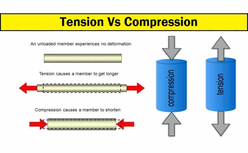
When material bends:
- The inner surface compresses; the outer surface stretches.
- This can cause wall thinning, bulging, or pinched corners.
To manage this:
- Add relief holes at the base of intersecting bends (e.g., in box corners).
- Contour blanks to avoid bend bulges in critical areas.
- Add notes, such as “Bulging not allowed in this area,” if needed, on drawings.
10.0Dimensioning and Tolerancing Formed Features
Bends introduce multiple variables:
- Material thickness tolerance
- Angular bend tolerance (±1° typical)
- Station-to-station tooling accuracy
Design guidelines:
- Dimension from the inside of bends, not from the outside edge.
- When features are placed far from the bend, angular variation can cause large dimensional shifts. This should be factored into tolerancing.
- Complex forms may require qualifying or sizing operations to maintain accuracy.
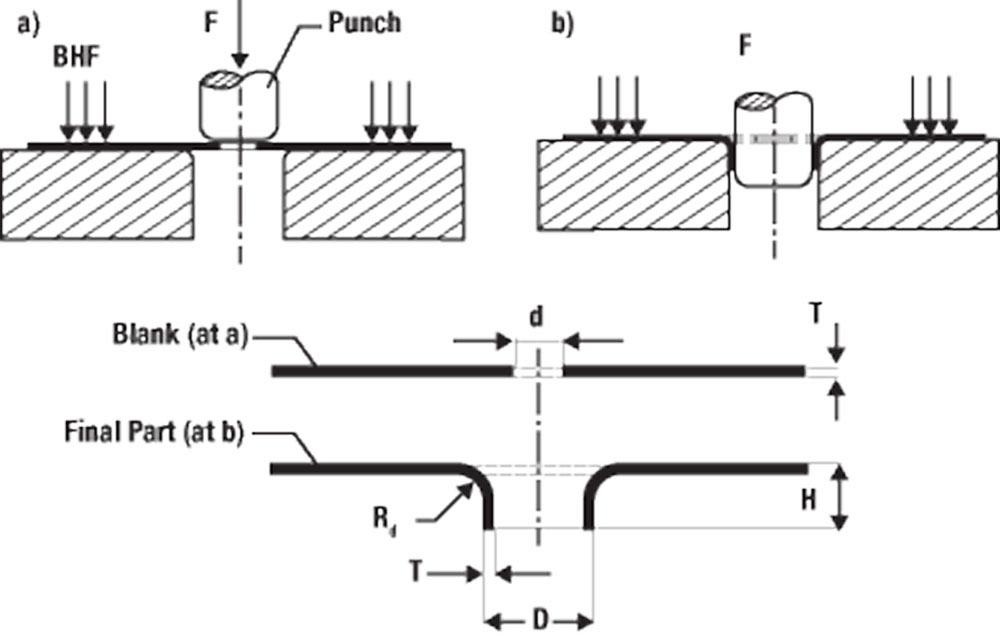
11.0Deep Draw Stamping: Design and Process Guidelines
What is Deep Draw?
Deep drawing pulls a flat blank over a radiused die and into a cavity, forming a closed-bottom shell or cylindrical cup. Unlike stretch forming, the material is pulled, not stretched.
Deep Draw Mechanics
The process has two stages:
- Cupping: Punch contacts the blank and stretches the material, creating a shock line(a visible thinning around the bottom radius).
- Drawing: The material walls thicken(up to +10% of original thickness) as it flows inward and downward.
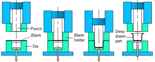
Design Implications for Deep Draw
- The punch must be tapered, allowing part removal.
- Shells will have a natural taper from the bottom (narrow) to the top (wide).
- Material grain direction can cause out-of-round shells. A flange can help maintain roundness.
- Pinch trimmings leave a partial inside radius and a sharp outer edge. Machining is required if a flush cut is critical.
Specifying Drawn Shells
Because thickness varies through the draw:
Use one of the following:
- Material starting thickness
- Minimum wall thickness
- Maximum wall thickness
Dimension ID (inside diameter) when referencing punch dimensions.
Dimension OD (outside diameter) when referencing the final product, noting taper allowance.
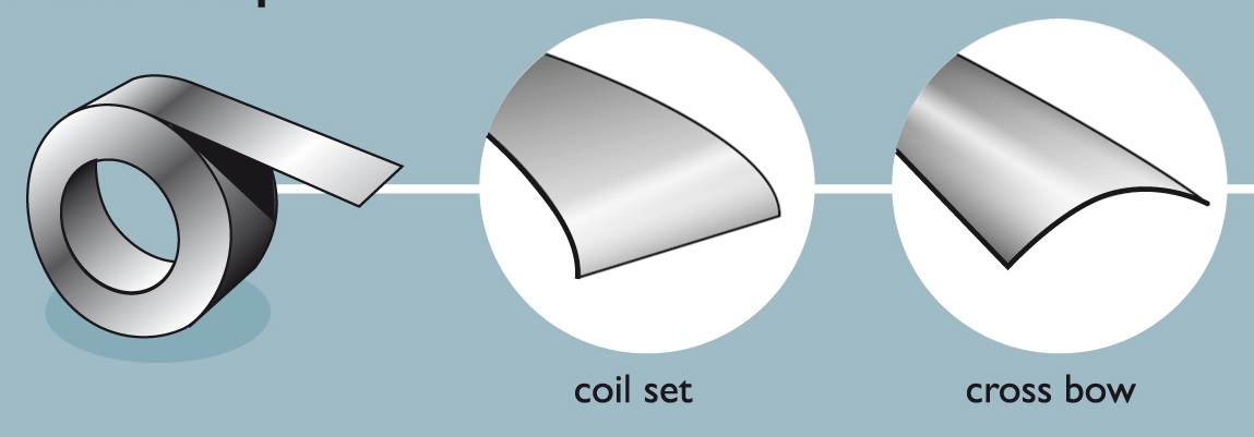
12.0Flatness in Metal Stampings
Material-Related Distortion
Coil-fed strip metal introduces two main issues:
- Coil set(curved lengthwise): can often be straightened using a precision leveling machine or roller flattening system to correct longitudinal coil curvature.
- Crossbow(curved across width): much harder to remove and often affects final flatness.
Process-Induced Distortion
Blanking and forming stresses bend or roll material edges, especially in:
- Thicker materials
- Harder alloys (e.g., stainless steel, high-strength steel)
To minimize distortion:
- Avoid placing perforations too close to each other or near edges—leave ≥1.5× thickness.
- Keep holes ≥2× thickness away from bends or forms.
- If not possible, enlarge hole tolerance to account for distortion.
13.0Managing Surface Cosmetics in Stamped Parts
Tool Marks
Due to high forces, tool marks are unavoidable in many cases:
- Wipe formingleaves scratches on outer bends.
- Drawing causes shock lines.
- Coining and embossing leave visible pressure marks.
Creative die design and fine tooling surfaces can minimize these, especially where cosmetic appearance matters.
14.0Handling and Surface Protection
Most stampings are:
- Bulk-handled through production lines.
- Mass finished(tumbling, deburring, etc.).
- Packed in bulk, often without individual protection.
For sensitive parts:
- Define cosmetic requirements on the drawing.
- Consider individual packaging or final finishing operations if surface integrity is critical.
15.0Final Thoughts
By understanding and applying these metal stamping design principles, you can dramatically improve part quality, reduce production costs, and ensure consistent manufacturability. Whether it’s choosing the right material, tolerancing a deep draw, or designing form-friendly features, collaboration with experienced tooling engineers and manufacturers will yield the best results.
16.0Frequently Asked Questions (FAQ) about Metal Stamping Design
1. What materials are best suited for metal stamping?
Materials commonly used in metal stamping include carbon steels, stainless steels, aluminum, copper, and brass. The best choice depends on your application’s needs for strength, formability, conductivity, corrosion resistance, and cost efficiency.
2. How do I minimize burrs in metal stamped parts?
Burrs are a normal by-product of blanking and piercing. To minimize burr height:
- Use optimal punch/die clearance (~8–10% of material thickness per side)
- Ensure tool sharpness and maintenance
- Consider secondary deburring or tumbling operations for cosmetic applications
3. What’s the typical tolerance I can expect in stamped metal parts?
Standard dimensional tolerances for holes or edges can often be held to ±0.002” in high-precision applications. However, tolerances may loosen depending on:
- Material thickness and temper
- Tool wear and stroke speed
- Feature location (flat vs. formed planes)
4. Can metal stamping achieve complex 3D shapes?
Yes. Using progressive dies and compound tooling, intricate shapes, including bends, offsets, louvers, and shallow draw, can be achieved. For deeper shapes, deep draw stamping is employed, though it introduces wall thickening and tapering.
5. How does material springback affect bending accuracy?
Springback is more prominent in harder materials and tighter bends. To compensate:
- Over-bend angles slightly
- Account for the material grain direction and temper
- Use forming tools designed to counter the springback effect
6. What’s the minimum spacing required between holes in stamped parts?
To avoid distortion, holes should be spaced at least 1.5× material thickness apart. For holes near a bend, keep them 2× material thickness away from the bend radius.
7. Why is my stamped part not perfectly flat?
Flatness issues may result from:
- Coil set and crossbow in raw strip
- Excessive material thinning near pierced features
- Forming operations near unsupported edges
Tooling adjustments or secondary flattening operations can help mitigate this.
8. Can metal stamped parts be cosmetic-grade?
Yes, but cosmetic requirements must be clearly defined on the drawing. Tooling design, handling methods, and post-processing (such as tumbling or protective packaging) can all be tailored to meet visual quality standards.
9. What is the difference between deep drawing and stretch forming?
- Deep drawing pulls material into a cavity, causing wall thickening and a closed bottom.
- Stretch forming stretches the sheet over a die, thinning the wall and typically open-bottomed.
Deep drawing is ideal for high-strength, closed container-like shapes.
10. How can I reduce costs in metal stamping design?
- Use standard gauges and common alloys.
- Avoid overly tight tolerances unless required.
- Design features with manufacturability in mind (e.g., spacing, radii, leg lengths)
- Consult with a stamping house early in the design phase.e
References
https://www.researchgate.net/figure/Schematic-presentation-of-the-conventional-deep-drawing-process_fig1_283671332
https://www.thefabricator.com/thefabricator/article/bending/r-d-update-edge-fracture-in-hole-extrusion-and-flanging-part-i
https://aminds.com/understanding-sheet-metal-stamping-guideline-for-buyers/