This blog post introduces the basic terminology used in metal stamping and explains the core functions of stamping operations. We’ll also explore common die types, compare different stripper designs, and take a closer look at essential die processes used in manufacturing.
1.0Metal Stamping Dies: Simple, Compound, and Progressive Types
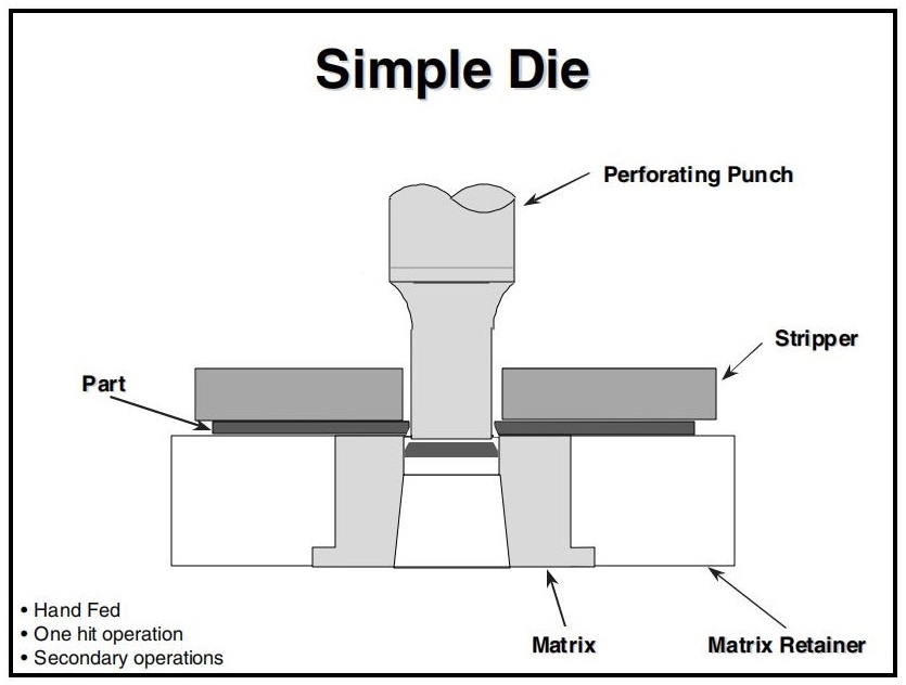
Perforation is typically the most severe operation performed in a die, as the punch press applies forces ranging from a few tons to over 1000 tons. Proper press alignment is essential. Although the die set contributes somewhat to alignment during operation, it cannot compensate for poor press alignment.
1.1Simple Die
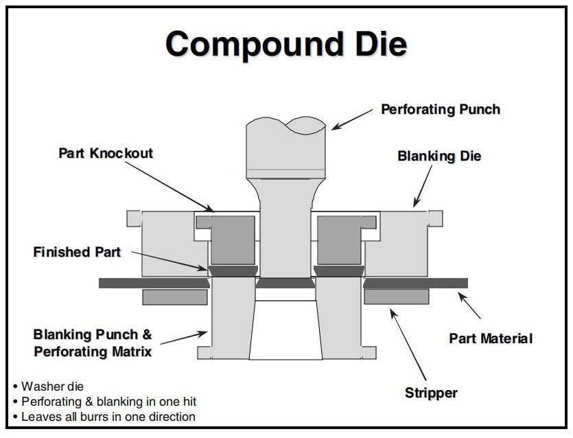
1.2Compound Die
A compound die blanks and perforates a part simultaneously in the same station. Typically, holes are punched downward while the part is blanked upward, allowing slugs to fall through the die. Since the part remains in the die, a method for part removal is necessary.
Compound dies are usually single-hit dies, though they can run continuously with a feeder if part removal is properly managed. Using an Open Back Inclinable (OBI) press in the inclined position with air blow-off assists in part removal.
Advantages of compound dies:
- Require minimal press space
- All burrs face one direction
- Excellent accuracy between holes and trim edges
- More economical to build than progressive dies
Disadvantages:
- Limited internal space makes the die components thin and weak
- Concentrated load and shock increase the risk of tooling failure (punch and matrix damage)
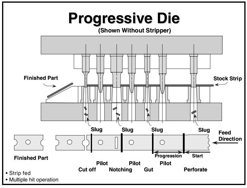
1.3Progressive Die
Progressive dies are an efficient method for converting raw coil stock into finished parts with minimal handling. As material feeds through the die, it is incrementally formed into a final product. Progressive dies usually run from right to left, advancing the strip one
progression per press cycle. Early stations typically punch pilot holes to ensure proper alignment in later stages.
There are many variations of progressive die designs; the one shown here illustrates common operations and terminology.
2.0 Metal Stamping Strippers: Fixed, Urethane, and Spring Types
Stripping the part from the punch tip after perforation is essential. Common stripper types include:
- Fixed
- Urethane
- Spring
The stripping force depends on the material type, thickness, and punch-to-matrix clearance. It ranges from nearly zero to as much as 25% of the perforating force. Most applications require no more than 10%.
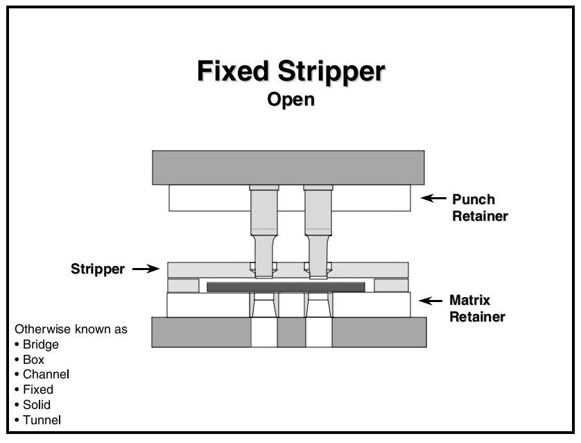
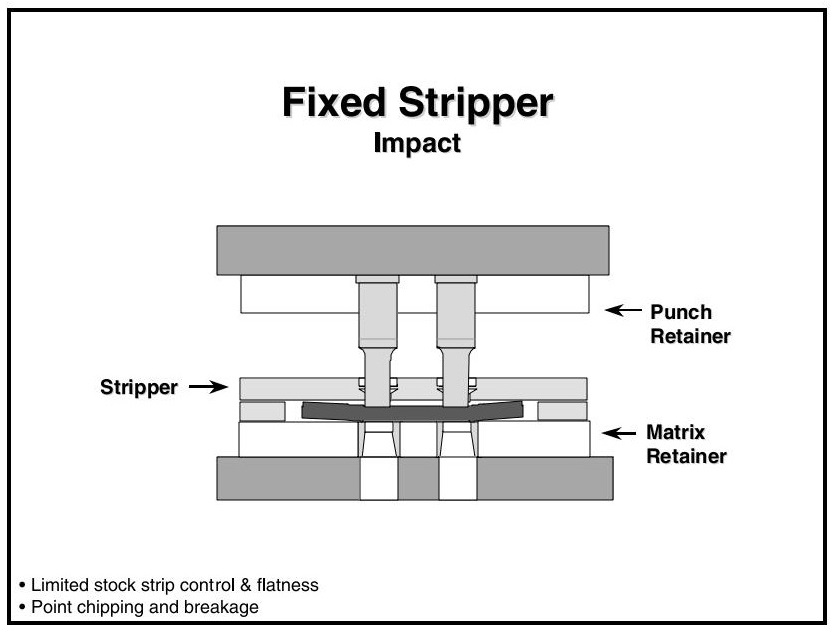
2.1Fixed Stripper
Also known as:
- Box
- Channel
- Solid
- Bridge
- Positive
- Tunnel
A fixed stripper is a steel plate with a clearance slot, mounted in a fixed position on the die retainer. It includes holes to allow punches to pass through without interference. As the die opens, the stripper holds the material down and removes it from the punches.
Drawbacks of fixed strippers:
- Do not hold the stock strip flat
- Cannot absorb snap-thru shock
- Result in poor part flatness and premature punch failure
- Common clearance is 1.5× material thickness (typically 1/16″–1/8″)
- Material deformation under the punch point can lead to:
- Punch chipping
- Lateral movement of both the part and the punch
- Poor part quality
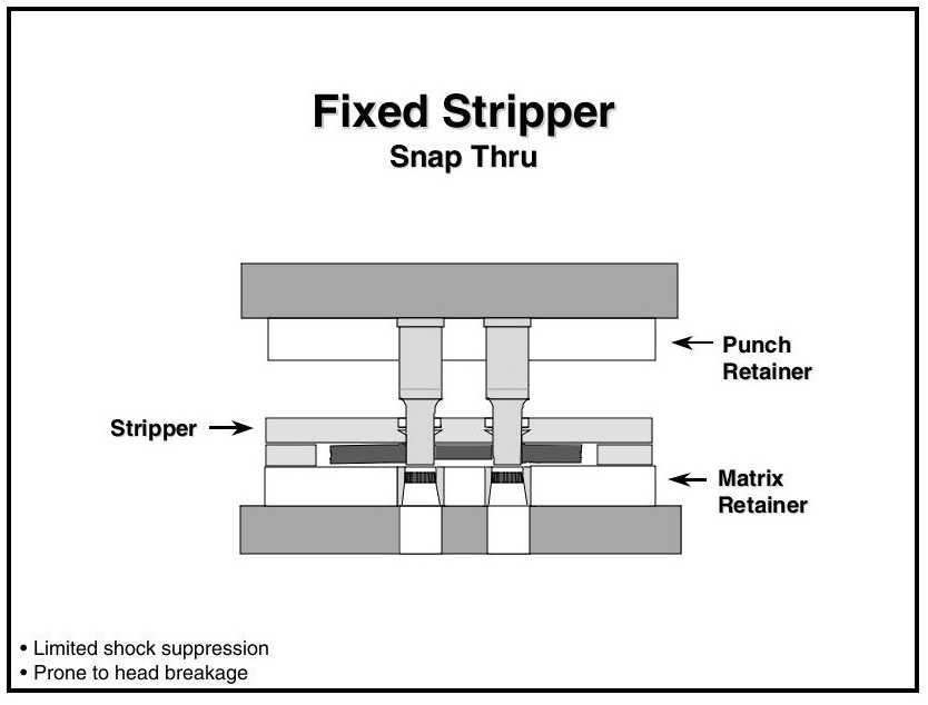
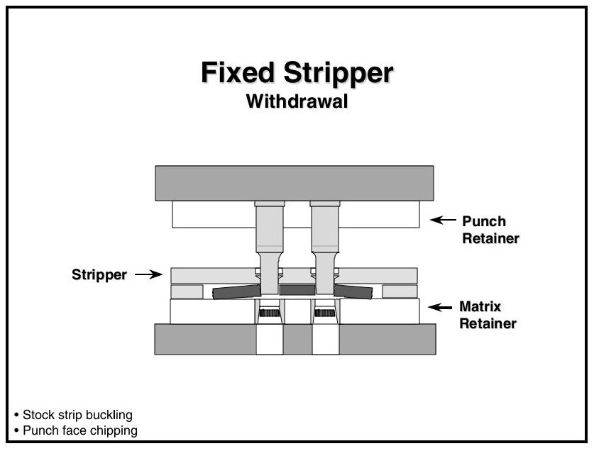
Snap-thru causes sudden unloading, creating shock that may break punch heads. Material buckling during the cycle binds the part to the punch ends, increasing stripping force and risking punch face damage.
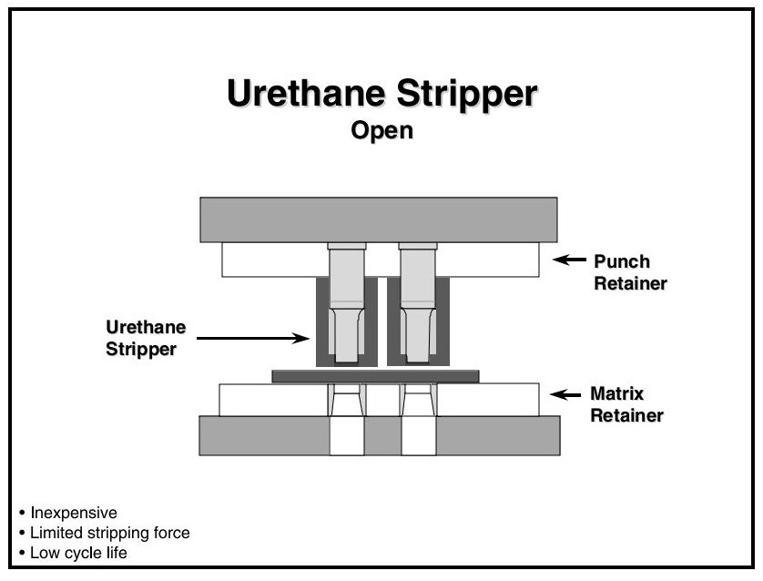
2.2Urethane Stripper
Urethane strippers are cost-effective and simple. They press-fit onto punches to prevent them from falling into the die.
Cautions:
- Urethane fatigues over time and can loosen
- May fall into the die and cause damage
- Molded heads improve retention and durability
Performance Considerations:
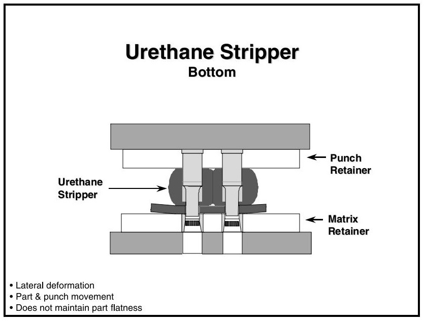
- Urethane deforms rather than compresses. If there isn’t enough space for volume displacement, tooling components may be moved or damaged.
- Cannot hold the strip flat
- Can cause air entrapment around punch points, leading to slug pulling
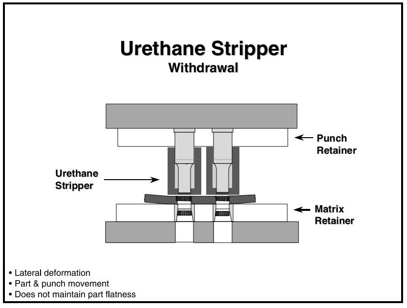
- Lateral movement during deformation may cause alignment issues. During retraction, the urethane returns to shape and strips the part, but may distort the part.
- Some urethane strippers feature steel washers to reduce distortion. However, this can be dangerous with shaped punches or high pre-load, as contact with the washer may cause punch failure.
Recommended design: A dual-grade urethane—high hardness for the face, medium hardness for the body—offers the best balance of flatness and durability.
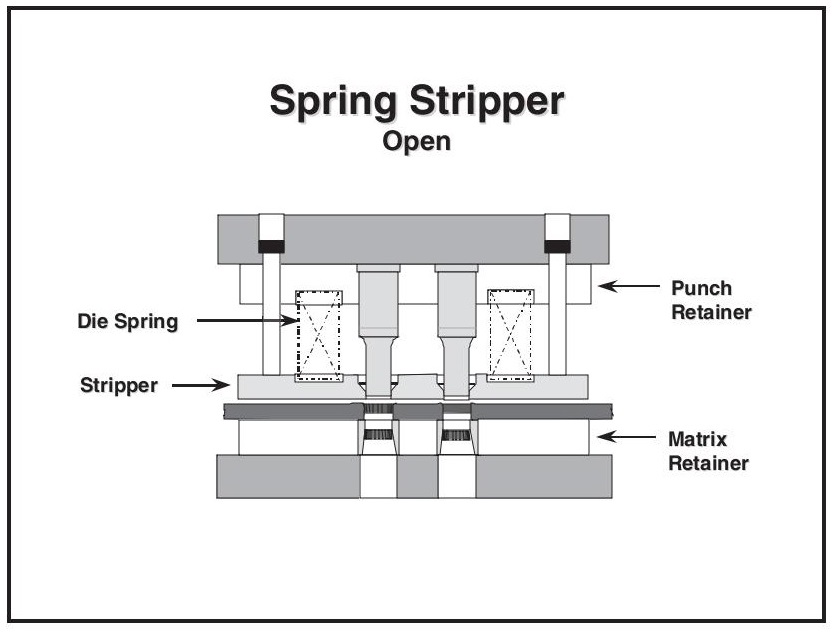
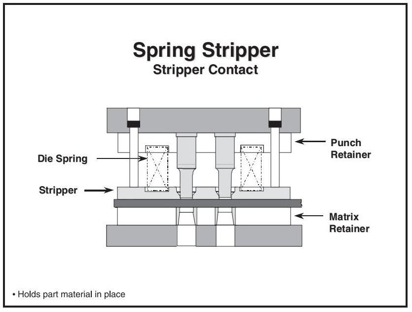
2.3Spring Stripper
Spring strippers offer superior performance. They:
- Hold the stock strip or part flat during perforation
- Prevent lifting or hanging on punches
- Allow visual monitoring of die performance after each stroke
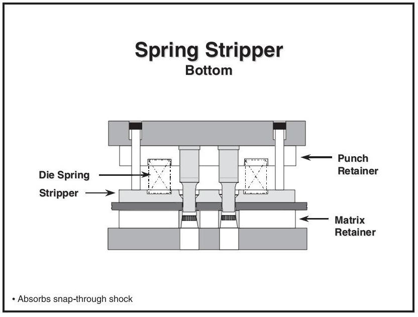
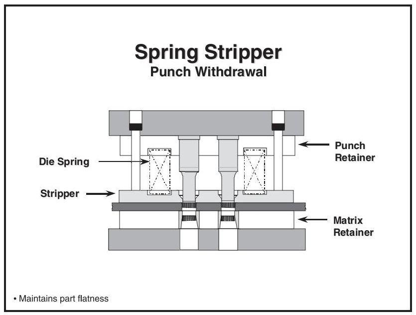
- Absorb snap-thru shock and eliminate withdrawal shock, extending tool and press life
They hang below the punch tips and are among the first components to contact the part, keeping it fixed throughout the cycle.
Continuous pressure during the working stroke improves:
- Tool reliability
- Part quality
- Press longevity
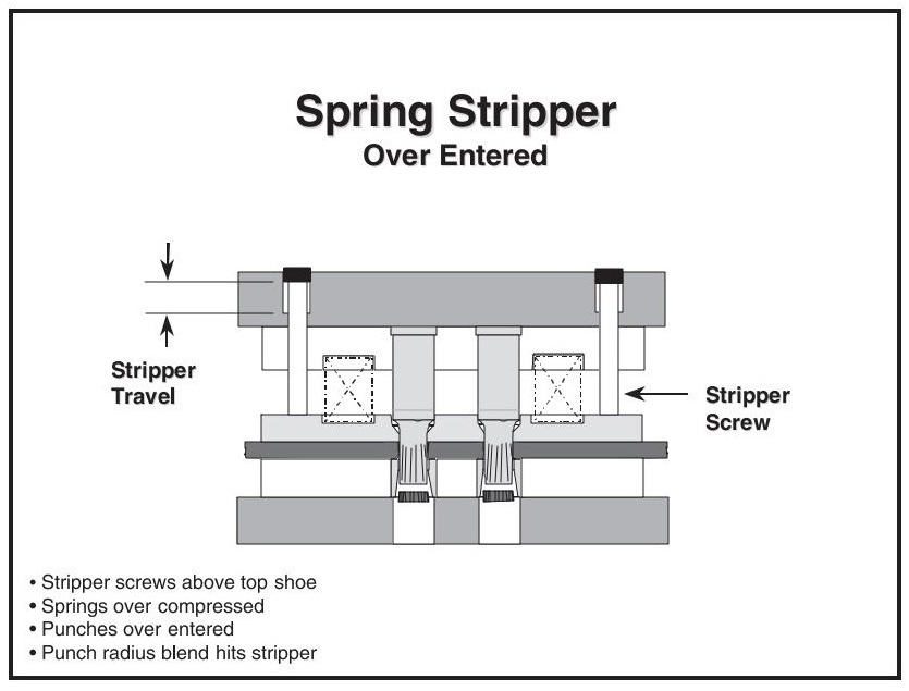
Important: Over-entry (closing the die below the recommended shut height) can cause:
- Stripper screws to break or bend
- Die spring over-compression
- Stripper interference with punch radii
- Galling and punch wear
3.0Metal Stamping Punching Techniques: Perforating, Piloting, Lancing & More
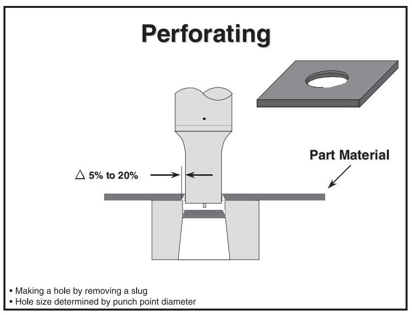
3.1Perforating
Perforating creates a hole by punching out a slug. The punch shears the slug and pushes it through a die opening (matrix), which is slightly larger than the punch point. Consistent clearance around the punch ensures accurate results.
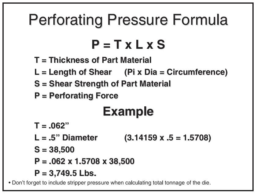
Tonnage Requirements:
Multiply material thickness × cut length (or hole perimeter) × material shear strength
For round holes:
Perimeter = π × Diameter
Typical material shear strengths:
- Aluminum: ~50% of tensile strength
- Cold-rolled steel: ~80% of tensile strength
- Stainless steel: ~90% of tensile strength
Stripper Pressure
Stripper pressure should be included when calculating die tonnage.
- Minimum = 8% of perforating force
- Some tooling manufacturers require up to 25%
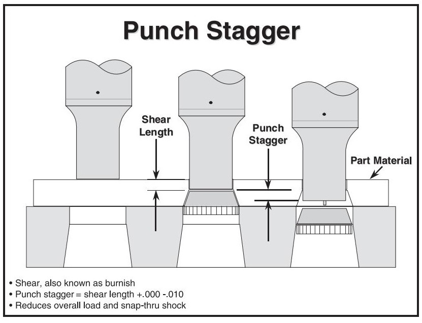
3.2Punch Staggering
Stagger punch lengths to reduce impact and snap-through shock. Split punches into 2–3 groups:
- Each group reduces shock by half or a third
- Typical staggering amount = stock thickness
Better Approach: Use Burnished Length
- Staggering equal to or slightly less than the burnish length greatly reduces both impact and snap-through shock
- The next punch group contacts the material before the first group snaps through
- Snap-through energy of the first group assists the second
This is especially critical for high-speed stamping:
- Reduces punch entry
- Minimizes wear and slug pulling
- Increases feed time
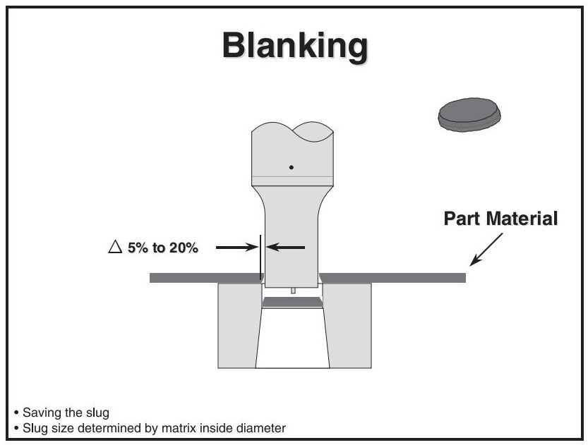
3.3Blanking
- Blanking cuts the full outer profile of a part in one operation.
- Similar to perforating, but the slug becomes the finished product
- Burr direction is opposite of internal holes/notches (unless blanking upwards in a compound blank die)
- Tonnage calculation is the same as perforating
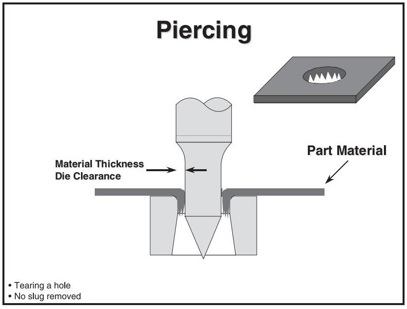
3.4Piercing
- Piercing creates holes without removing slugs
- The punch tears the material open, forming a ragged edge
- Similar in appearance to holes in a food grater
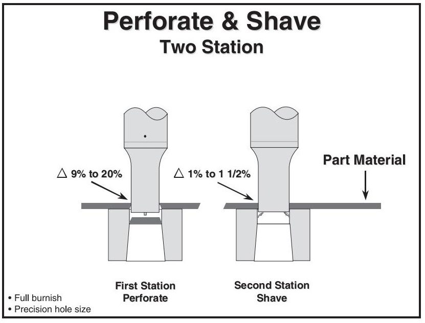
3.5Perforate and Shave
Shaving creates a high burnish (shear) area within a hole. It uses two stations:
- First station: Standard perforating with optimized clearance for tool life and reduced work hardening
- Second station: Cuts a hole to the final size using tight clearance
- Clearance per side: 1–1.5% of material thickness (2–3% total)
- Too much clearance = hole shearing and re-breaking
Tool Sizing:
- Shave punch = final hole size
- Shave matrix = 2–3% larger than the punch
- Perforating punch = smaller than shave punch, clearance maximized without excessive burr
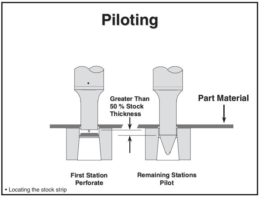
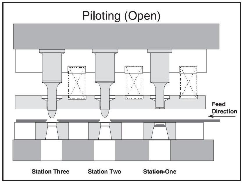
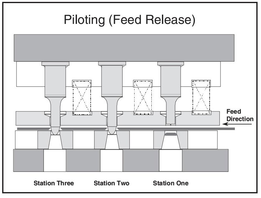
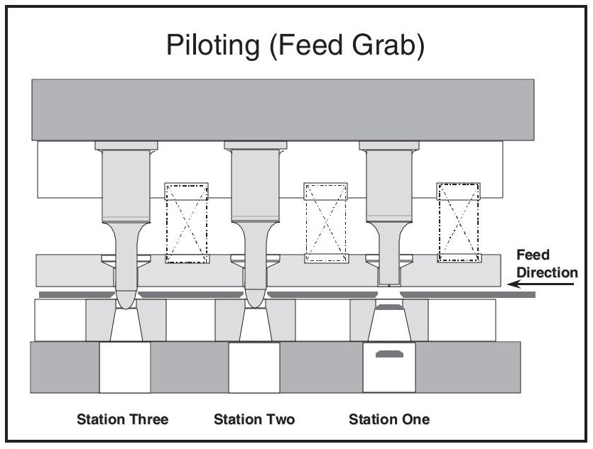
3.6Piloting
Pilots are critical for accurately locating the stock strip or part material within the stamping tool. They ensure proper alignment before each operation begins.
Function and Timing:
- Pilots engage pre-existing holes in the strip or part before the stripper makes contact
- Once the pilot nose begins entry, the feeder releases the material, allowing the pilot to pull the stock into the proper position
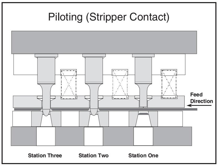
- The stripper then clamps the material, locking it in place
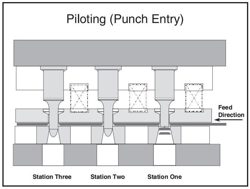
- Perforating punches should be the last components to contact the material, after the pilot and stripper
Pilot Design:
Pilots typically have rounded or tapered noses to guide entry without distorting the material
The pilot point diameter is usually 0.001” smaller than the punch diameter used to create the locating hole to prevent sticking during entry
Working Length:
In most simple die applications, pilot working lengths are 0.080” to 0.125” longer than the perforating punches
Die Entry and Clearance:
Designers differ on clearance strategy:
- Tight clearance (≤ 0.0005″) below the part provides lateral support and precise location—ideal for forming or thick materials
- Drawback: In case of misfeeds, tight clearance can cause excessive stripping force, galling, or even pull the pilot out, especially in ball-lock pilots
- Material thickness per side: Allows room for the material to extrude down without grabbing the pilot
- Drawback: Springback can increase stripping force after extrusion
Recommended if misfeeds are frequent: Use standard perforating clearance to balance support and release
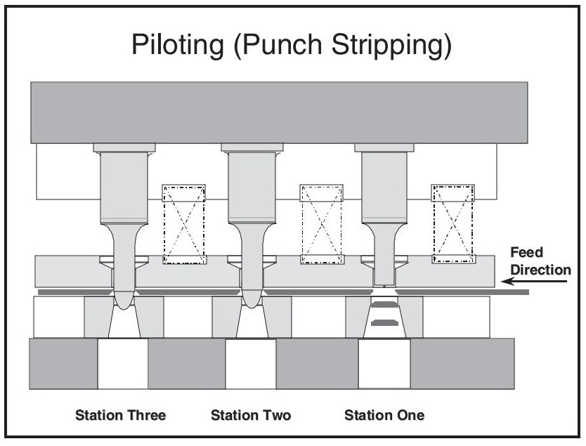
Stripping Considerations:
- Since pilots extend beyond the fully extended stripper, they can interfere with part stripping
- To reduce this risk, pilots should not protrude more than 1/3 to 1/2 of the material thickness beyond the stripper
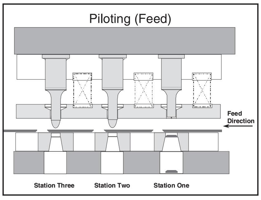
Feeding Sequence:
- Pilot enters the locating hole
- Feeder releases the material
- Pilot aligns the part
- The stripper clamps the part in place
- Punches engage the material
- After the pilot fully withdraws, the feeder advances the material to the next station.
- The cycle repeats
Pro Tip: Always time the feeder to engage the strip before the stripper lifts off the material. This ensures smooth progression and reduces the risk of misfeeds or part shifting.
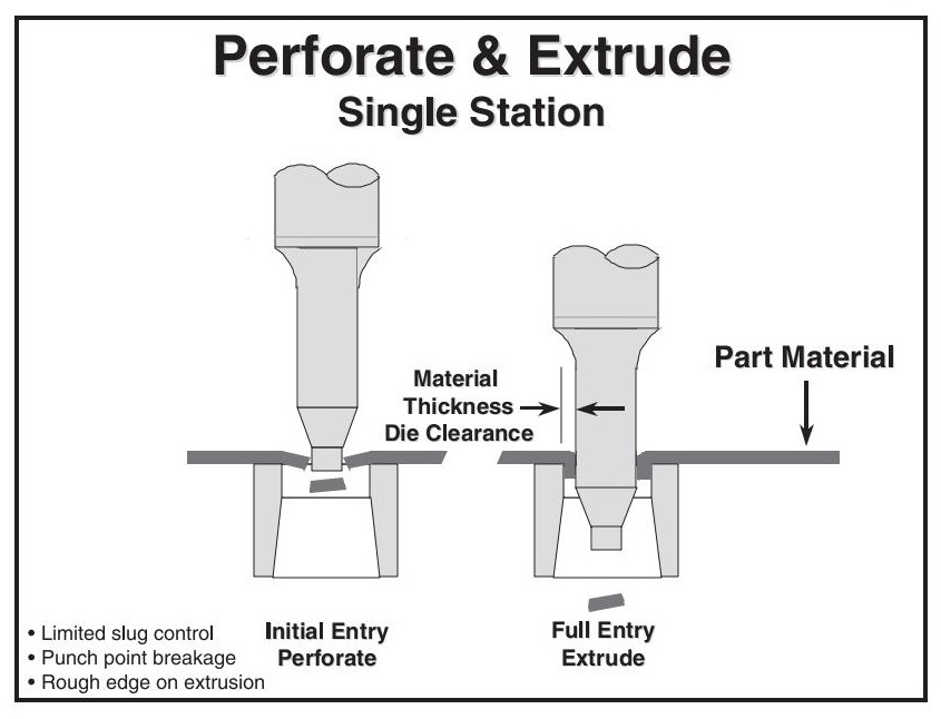
3.7Perforate and Extrude
Single-Station (Not Recommended):
- Rough extrusion edge
- Punch nose breakage
- Slug tumbling or jamming
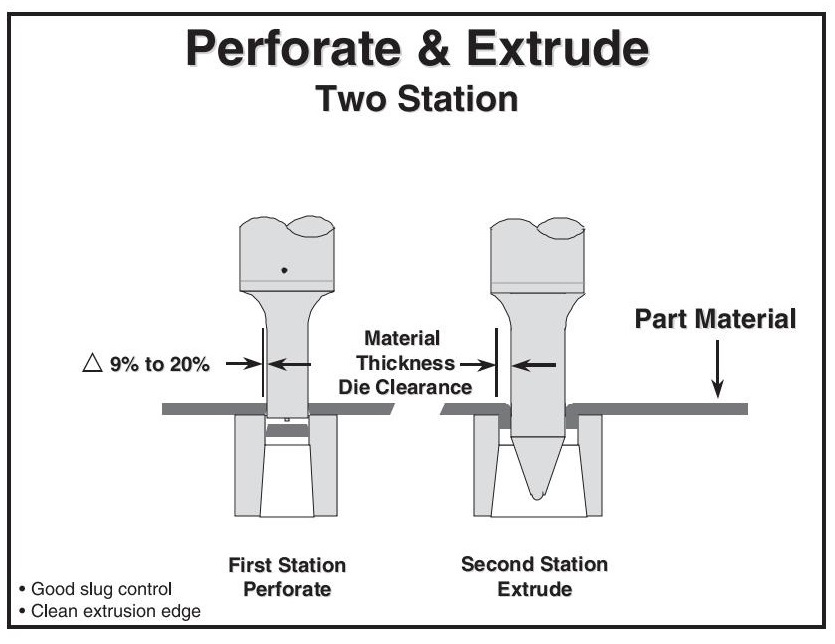
Two-Station (Recommended):
- 1st station: Perforates
- 2nd station: Extrudes
Advantages:
- Clean extrusion edge
- Good slug control
- Better tool reliability
Note: Standard pilots can serve as extrusion punches. Stone and polish them for the best performance.
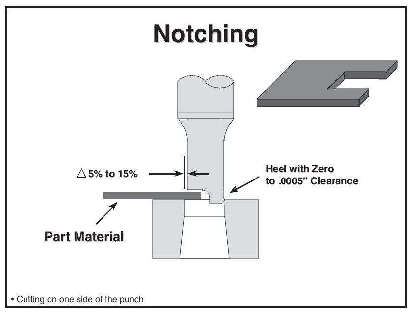
3.8Notching
Notching removes part of a hole at the edge of a part.
- Cutting occurs only on one side of the punch
- Causes lateral deflection → requires a heel opposite the cutting edge
- Heel should engage the matrix first
- Small radius on the heel avoids matrix damage
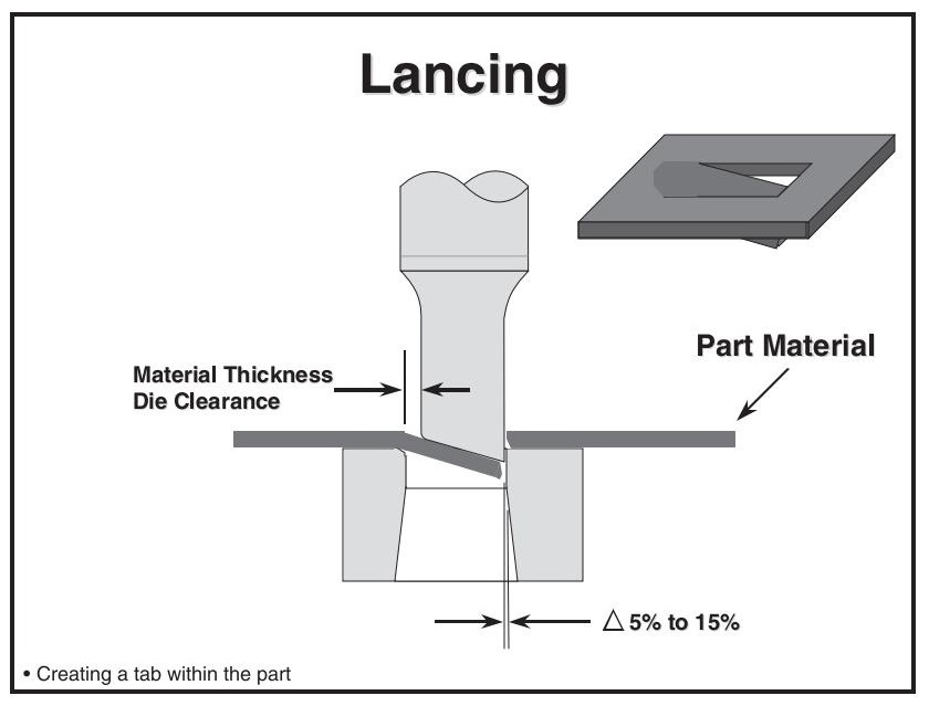
3.9Lancing
Lancing forms a tab within the part, without removing a slug.
- Usually includes a single shear angle
- Normal clearance is used for cut edges
- Connected edge is bent over the matrix
- Clearance under bend radius = material thickness
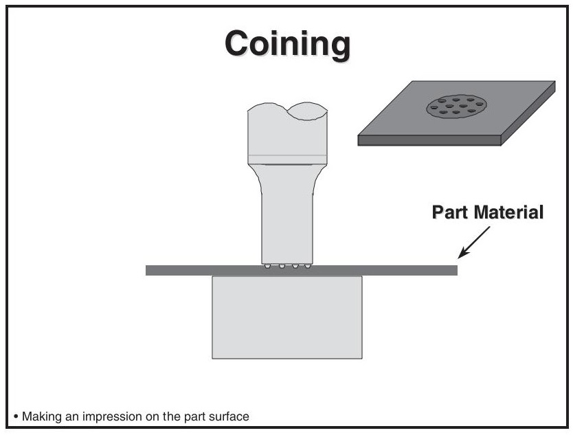
3.10Coining
Coining creates an impression on the part surface, on one or both sides.
Often used to:
- Thin local areas
- Displace material (No slug is removed)
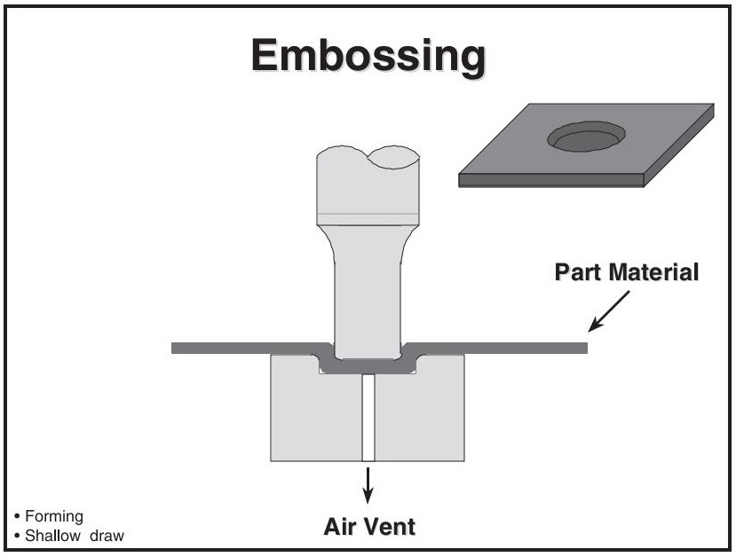
3.11Embossing
Embossing forms shapes in the material without thinning.
- Uses a punch to create a blind cavity
- Bottoms out to create a flat surface
- Air vent holes are essential to avoid part bulging or tool breakage
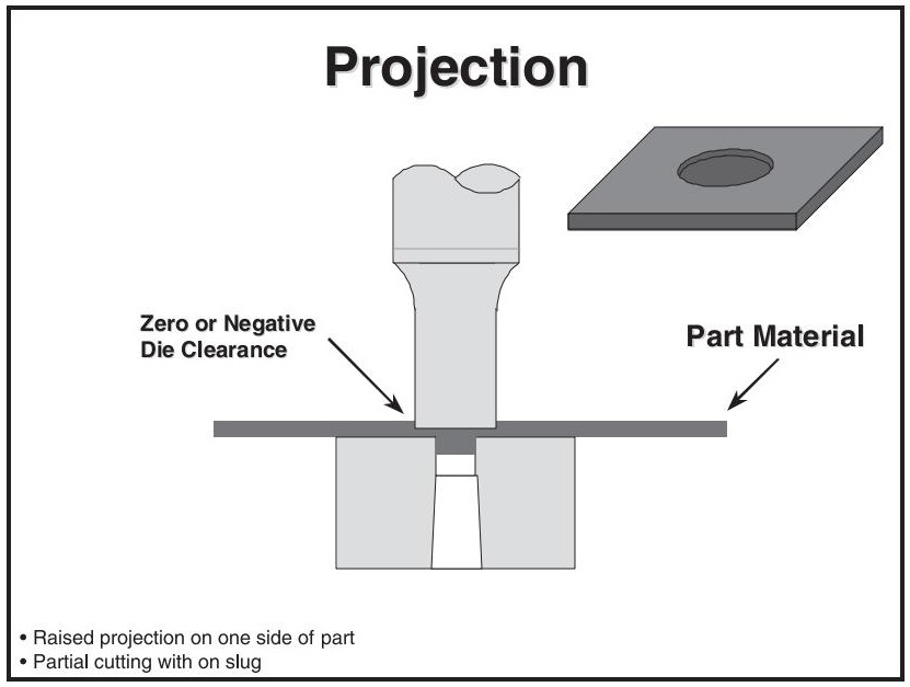
3.12Projection
Projection forms a raised feature on the matrix side of the material.
Achieved via zero or negative clearance
Used for:
- Welding contacts
- Locators for mating parts
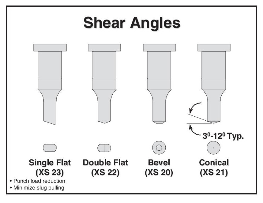
3.13Shear Angles
Shear angles reduce punch load and improve slug control.
| Type | Use Case & Notes |
| Single Flat | Reduces load but can cause lateral punch deflection, wear, and breakage; used on shaped punches |
| Double Flat (Rooftop) | Best for rectangular/oblong punches; avoid concave shapes |
| Bevel | Good load reduction and chip resistance; more prone to wear |
| Conical | Best for round punches; evenly distributes wear and minimizes slug pulling |
4.0Summary
Metal stamping is a foundational process in modern manufacturing, enabling the high-speed, high-precision production of metal parts. In this article, we’ve covered the core concepts and operations that drive this process:
- The roles of different die types—simple, compound, and progressive—and when to use each.
- The importance of the punch press and proper alignment in achieving consistent results.
- The function and design of various stripper types: fixed, urethane, and spring strippers.
- Key stamping operations include perforating, blanking, shaving, notching, lancing, coining, embossing, and more.
- Terminology and best practices, such as tonnage calculation, punch staggering, and pilot design.
Understanding these principles not only helps optimize production quality but also extends tooling life and reduces costs. Whether you’re just starting or looking to deepen your knowledge, mastering the basics of metal stamping lays a solid foundation for advanced die design and precision manufacturing.
5.0FAQ
What is the difference between simple, compound, and progressive dies?
- Simple die: Performs one operation per press stroke (e.g., punching or blanking).
- Compound die: Performs multiple operations at one station in a single stroke.
- Progressive die: Performs sequential operations across multiple stations as the strip moves forward.
Why is punch press alignment so important in stamping?
Poor alignment can lead to premature tool wear, part defects, or even press damage. The die set cannot fully correct misalignment issues from the press.
What are the pros and cons of compound dies?
- Pros: Compact, economical, accurate, and all burrs face one side.
- Cons: Limited internal space, risk of tool failure due to concentrated shock load.
What is the role of a stripper in a stamping die?
A stripper removes the part from the punch tip after perforation. It helps control stripping force, part flatness, and overall tool performance.
Which stripper type is best: fixed, urethane, or spring?
- Fixed: Low cost but less control; prone to shock and flatness issues.
- Urethane: Cost-effective but degrades over time; may cause misalignment.
- Spring: Best performance and reliability; absorbs shock and holds part flat.
How do I calculate perforating force (tonnage)?
Use the formula:
Material thickness × cut length (or hole perimeter) × shear strength
Example for round holes:
Perimeter = π × Diameter
What is punch staggering, and why is it important?
Staggering punch lengths reduce snap-through shock, protect tooling, and improve high-speed stamping performance.
What’s the difference between perforating, blanking, and piercing?
- Perforating: Removes slugs to form holes.
- Blanking: Cuts the outer profile; the slug is the final part.
- Piercing: Creates holes without removing material (tears or pushes open).
What is the purpose of piloting in stamping dies?
Pilots ensure accurate strip positioning before punching. They enter by locating holes to align material precisely for each press cycle.
What is coining vs. embossing?
- Coining: Displaces material to create fine surface details or reduce thickness.
- Embossing: Forms raised or recessed shapes without thinning the material.