- 1.0Conventional Spinning vs. Thickness-Reduction Spinning
- 2.0External Spinning vs. Internal Spinning
- 3.0Mandrel-Based vs. Mandrel-Free Spinning
- 4.0Cold Spinning vs. Hot Spinning
- 5.0Classification of Advanced Metal Spinning Processes and Analysis of Material Deformation Mechanisms
- 6.04. Advances and Applications of Advanced Metal Spinning Processes
- 7.0Conclusion
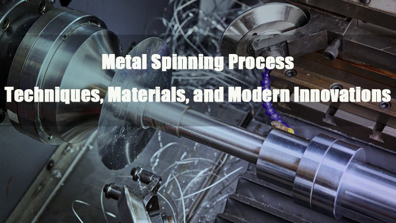
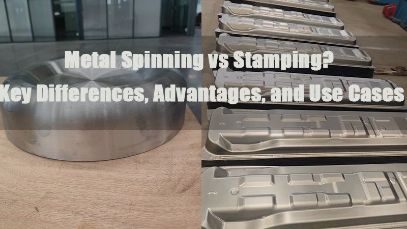
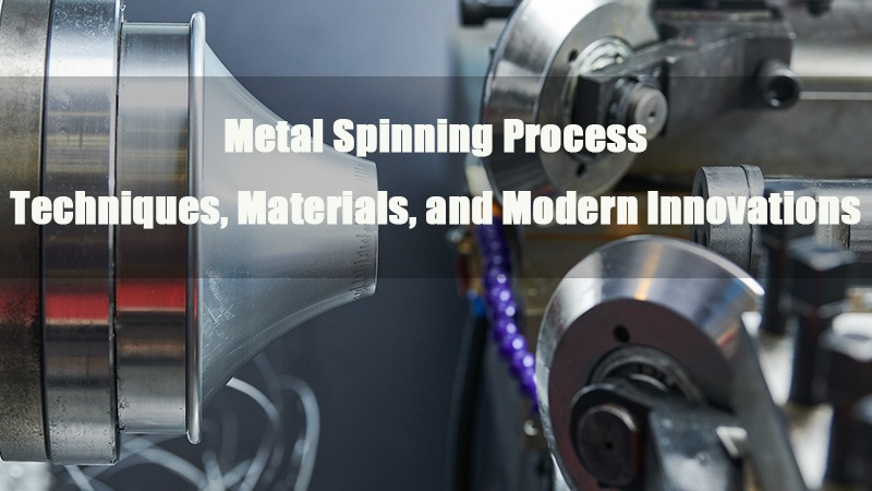
Metal spinning is a highly efficient near-net shaping process, widely used to produce axially symmetric, thin-walled, and hollow round components. The forming principle involves applying localized pressure with one or more rollers against a rotating metal blank or tube. As the blank spins with the spindle, the roller feeds into the surface, inducing continuous plastic deformation that shapes the material into the desired geometry.
Compared to other forming methods, metal spinning offers several advantages: lower forming loads, simpler tooling, high dimensional accuracy, excellent material utilization, and reduced production costs. It also significantly enhances the mechanical properties of the final part. The process excels at manufacturing lightweight components and is highly adaptable—making it ideal for high-performance applications across aerospace, automotive, medical, energy, and electronics industries.
pinning can accommodate parts with diameters ranging from large industrial components to those as small as 10 microns in experimental settings and thicknesses between 0.4 mm and 25 mm . However, traditional spinning is mainly suited for axisymmetric, round-section parts with uniform wall thicknesses, which limits its application scope. As demands for more complex geometries have grown, several new variants of spinning have emerged to overcome these constraints.
For instance, researchers have developed non-axisymmetric spinning techniques where the roller rotates with the spindle while the workpiece remains stationary. This method enables the forming of thin-walled parts with oblique or multi-axis geometries—eliminating the need for post-weld assembly. Other innovations include spring-controlled rollers added to conventional spinning lathes to produce non-circular hollow parts like tripod-shaped sections. In another advancement, “split-flow spinning” uses specially designed split rollers and support rollers to expand the radial design space during forming. More recently, gear-tooth spinning techniques have made it possible to create internal gear profiles directly via spinning.
Overall, metal spinning is evolving beyond traditional axisymmetric shapes into more complex and diverse structures. As a result, it is becoming an essential precision forming technology. With continued progress in materials science and process control, metal spinning is set to play an even greater role across a wider range of industrial applications.
Traditional Metal Spinning Classifications
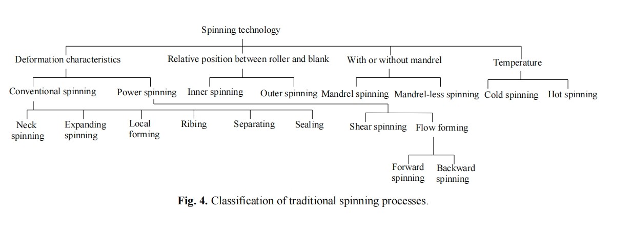
Traditional metal spinning processes are commonly categorized based on four key criteria:
- Deformation characteristics of the blank
- Relative position between the roller and the workpiece
- Use of a mandrel
- Temperature during the spinning process
Accordingly, traditional spinning techniques are typically divided into the following four categories:
1.0Conventional Spinning vs. Thickness-Reduction Spinning
| Process Type | Typical Parts | Forming Characteristics | Equipment Features | Application Examples |
| Non-Axisymmetric Spinning | Offset exhaust pipes | Integral multi-axis forming | Multi-axis synchronous control | Automotive tubing |
| Non-Circular Cross-Section Spinning | Tripod support tubes | Dynamic contour control | Multi-roller coordination | Medical device housings |
| Gear-Tooth Spinning | Multi-wedge pulleys | Localized material flow | Precision displacement control | Dampers, belt pulleys |
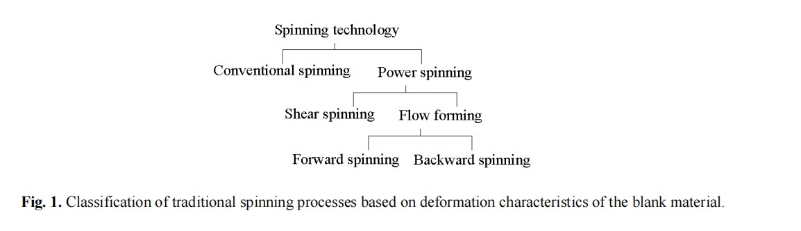
Based on material deformation characteristics, spinning processes are classified into two categories: conventional spinning and thickness-reduction spinning. The latter includes shear spinning and flow spinning.
- Conventional Spinning: The wall thickness of the blank remains essentially unchanged throughout the forming process. The final part retains the same thickness as the original blank.
- Thickness-Reduction Spinning: This process involves a reduction in wall thickness during forming. It is classified as a thickness-reduction method and can be further subdivided into:
- Shear Spinning: The wall thickness decreases while the contour of the original blank is maintained, commonly used for conical or cylindrical parts.
- Flow Spinning: Designed for tube-shaped components, where material thickness decreases as part length increases. Flow spinning can be performed in either a forward or backward direction.
Figure 1 illustrates the classification of spinning methods based on deformation characteristics.
2.0External Spinning vs. Internal Spinning
Based on the roller’s position relative to the workpiece, spinning processes are divided into:
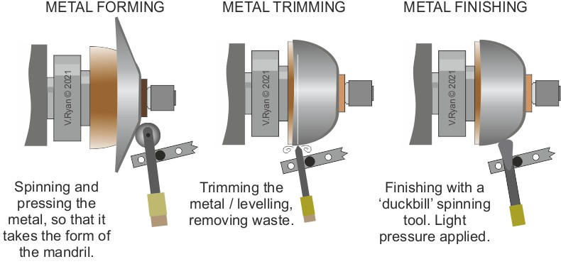
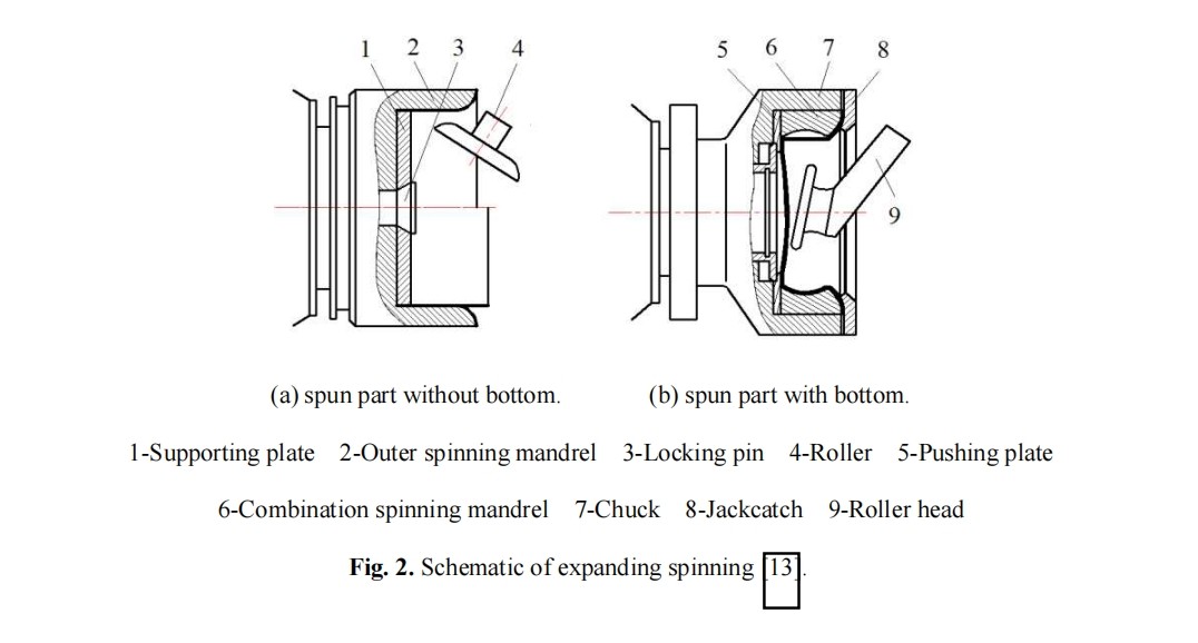
- External Spinning: The roller applies pressure from the outside of the workpiece while a mandrel supports it from within. This is the most common configuration.
- Internal Spinning: The roller acts from the inside out, pressing the material outward. This method is used for specialized structures or inverse forming requirements.
Figure 2 shows typical setups for both external and internal spinning.
3.0Mandrel-Based vs. Mandrel-Free Spinning
Depending on whether a mandrel is used, spinning operations can be categorized as
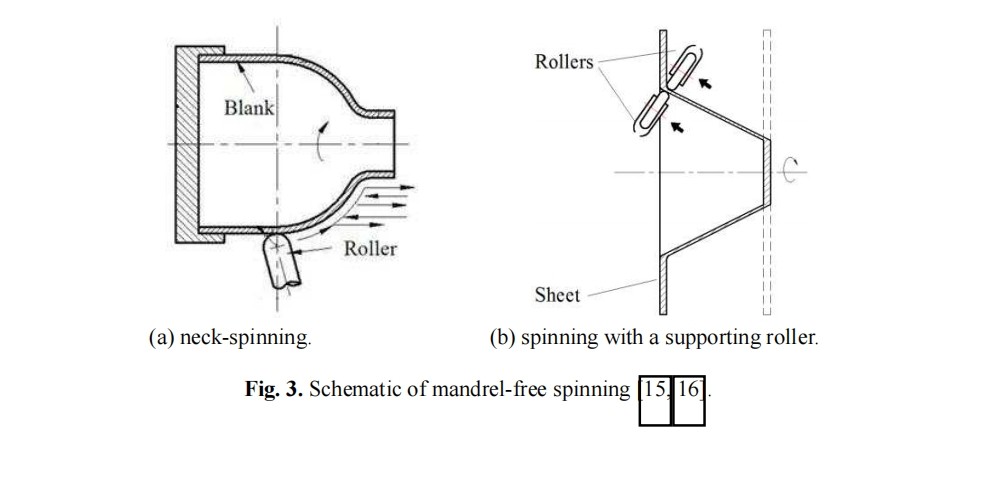
- Mandrel-Based Spinning: Each part is formed with a custom-designed mandrel. The blank is held in place by the tailstock, and the mandrel dictates the final shape of the product.
- Mandrel-Free Spinning: Applied in specific forming operations such as necking or sealing pressure vessels, or when working with large parts. In such cases, an internal support roller may replace the mandrel to reduce machine load.
Figure 3 displays the structural configuration and applications of mandrel-free spinning setups.
4.0Cold Spinning vs. Hot Spinning
Based on the processing temperature, spinning can be divided into:
- Cold Spinning: Performed at room temperature, suitable for materials with good plasticity and moderate wall thickness.
- Hot Spinning: Conducted above the material’s recrystallization temperature. This method reduces forming forces and is better suited for high-strength or brittle materials.
Figure 4 summarizes the logic behind these four traditional spinning classifications.
5.0Classification of Advanced Metal Spinning Processes and Analysis of Material Deformation Mechanisms
The new classification expands upon traditional dimensions by introducing additional criteria such as cross-sectional geometry and relative axis orientation to accommodate complex, non-axisymmetric components.
- Relative position between rotational axes
- Geometric shape of the part cross-section
- Characteristics of wall thickness variation
Based on these criteria, advanced spinning techniques can be divided into three main categories: non-axisymmetric spinning, non-circular cross-section spinning, and gear-tooth spinning.
5.1Non-Axisymmetric Spinning
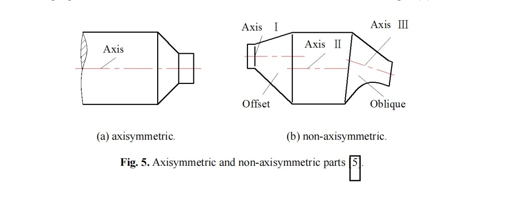
Spinning parts can be classified into axisymmetric and non-axisymmetric based on their rotational axis configuration:
- Axisymmetric Spinning: The workpiece rotates solely around a single axis, with a standard circular cross-section.
- Non-Axisymmetric Spinning: The workpiece is rotated around a single axis, but its geometry or the spinning path is intentionally offset or tilted, creating non-axisymmetric features.(see Figure 5).
Non-axisymmetric spinning typically includes two key approaches: offset spinning and tilted spinning.
During processing, tubular blanks are fixed by a fixture and undergo synchronized rotation and feed via a roller assembly. The spinning path can be modified by translating or rotating the fixture to achieve offset or tilt, thereby altering the blank’s positional state. Rollers feed radially, evenly distributed around the workpiece, and rotate synchronously with the spindle.
- Offset Spinning: Before each spinning path begins, the blank is shifted perpendicular to the workpiece axis by a preset offset, then fed along the roller axis until reaching the target offset (see Figure 7a).
- Tilted Spinning: The blank is tilted at a specific angle relative to the horizontal plane of the worktable before feeding, gradually adjusting the tilt angle to the target value ϕ0° during the feed (see Figure 7b).
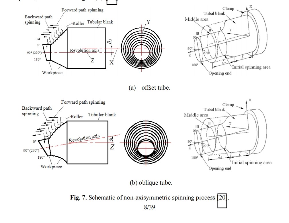
Stress and strain distributions in non-axisymmetric spinning show significant non-uniformity. Maximum stress and strain typically occur at the greatest offset or tilt positions (e.g., at 0°), while symmetric positions (e.g., 180°) exhibit lower values. Notably, axial strain variation is especially pronounced in tilted spinning.
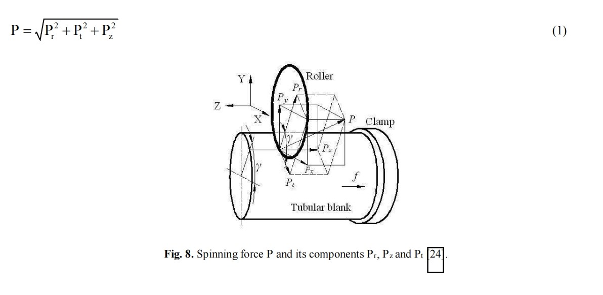
The distribution of spinning pressure can be analyzed using the Slab method. Results indicate thatIn typical spinning processes, radial and axial forces tend to dominate, while tangential forces are generally smaller, though their magnitude may vary based on toolpath and geometry, with the main forces concentrated in the latter two. Radial spinning pressure Pr and axial spinning pressure Pz can be derived via formulae shown in Figure 8.
5.2Non-Circular Cross-Section Spinning
Based on the cross-sectional geometry, advanced spinning can be further divided into:
- Circular Cross-Section Spinning: The distance from the outer edge of the cross-section to its geometric center remains constant.
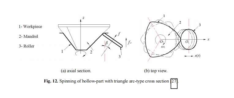
- Non-Circular Cross-Section Spinning: This distance varies with the angle. Common cross-sectional shapes include triangular arcs, quadrilateral arcs, pentagonal, and other polygonal forms (see Figures 11 and 12).
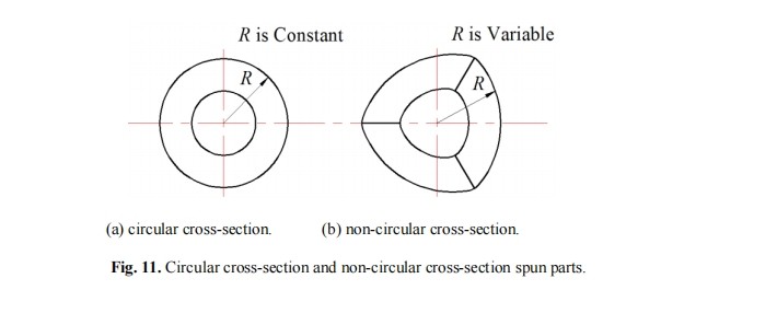
Experiments have demonstrated that spinning is effective for forming various complex hollow parts with non-circular cross-sections. Such processes typically employ contour-driven toolpaths to accommodate cross-sectional changes while ensuring uniform wall thickness.
In practical forming, the roller feed rate must dynamically adjust according to changes in the geometric center of the part. For non-circular cross-sections, when the roller moves from the midpoint of a side towards the adjacent vertices, the feed speed needs to increase with the growing distance. To achieve uniform wall thickness, the clearance between the mandrel and roller should be maintained equal to the initial blank thickness.
6.04. Advances and Applications of Advanced Metal Spinning Processes
In recent years, numerous advanced spinning technologies have been developed to meet the manufacturing demands of complex geometric parts. These innovations demonstrate significant advantages in enhancing production efficiency, reducing costs, and optimizing part performance. This section briefly introduces key processes and their industrial applications, while analyzing critical issues related to tooling design, process control, and part defects.
6.1Non-Axisymmetric Spinning
A non-axisymmetric spinning technique has been successfully employed to manufacture multi-rotational-axis tubular components, such as offset and tilted shaft structures. This process enables integral forming of hollow parts with multiple non-collinear centerlines, eliminating the need for traditional welding and assembly.
For example, automotive exhaust pipes typically consist of a straight midsection tube and two end tubes oriented in different directions. Conventional manufacturing involves stamping and welding three separate segments, which is labor-intensive and prone to thermal deformation and fatigue cracks at weld seams.
The novel spinning process uses 6061 aluminum alloy tubing (100 mm diameter, 1.8 mm wall thickness) to produce the entire structure in a single forming step. Compared to traditional methods, material utilization improved from approximately 70% to 90%, while the number of process steps was reduced from 10 to 2, greatly lowering costs and defect risks. Furthermore, the associated CNC spinning equipment features multi-axis synchronous control, specifically designed for high-precision forming of complex non-axisymmetric geometries.
6.2Non-Circular Cross-Section Spinning
To address the forming of non-circular hollow parts, various spinning techniques have been developed. For instance, by adjusting the radial offset of the rollers, elliptical cross-section components can be directly produced on a spinning lathe, suitable for ductile materials such as aluminum sheets. Typical parts have a major axis of 110 mm, minor axis of 90 mm, and wall thickness around 1 mm.
Another approach utilizes a spindle structure aligned with the rotation direction, enabling versatile cross-sectional geometries. This method controls roller toolpaths to strictly conform the material to the mandrel profile, yielding asymmetric cross-section parts (e.g., elliptical, quadrilateral) with excellent fit and minimal springback.
Moreover, adding a dual-roller mechanism with opposing spring control to traditional spinning equipment has enabled the successful fabrication of tripod-shaped cross-section parts. This innovation significantly optimizes wall thickness distribution, reducing maximum thickness variation by up to 24%.
To further enhance forming accuracy, researchers have developed electronically synchronized spinning systems that control the phase relationship between spindle rotation and roller feed, achieving highly consistent forming of complex cross sections—particularly beneficial for elliptical and irregular shapes in mass production.
6.3Gear-Tooth Spinning
Gear-tooth spinning has found applications in manufacturing complex parts such as V-belt pulleys, dynamic dampers, and automotive wheels. Conventional production often relies on forging or casting followed by machining, resulting in high material waste, low efficiency, and poor dimensional accuracy.
By utilizing near-net-shape spinning technology, steel sheet blanks of 2.5 mm thickness can be directly spun into toothed pulleys …without molds or with only a mandrel. This process maintains tight tolerances. The tooth profiles are formed by localized material flow rather than actual material thickening. The effective tooth height corresponds to 0.3 mm of radial displacement over the base thickness.
Compared to traditional methods, this not only improves material strength and service life but also significantly raises yield rates.
In practical operations, defects such as base diameter expansion, opening-end warping, or asymmetric bell-shaped cross sections may occur. These issues are closely linked to material flow behavior, roller path design, and process parameters, requiring optimization in equipment control and process planning.
7.0Conclusion
This paper proposes a novel classification method for metal spinning processes that encompasses a wide variety of geometric part shapes. It integrates the classification dimensions of traditional spinning techniques with the diverse advanced spinning technologies developed in recent years. Traditional spinning processes are typically categorized based on material deformation characteristics, relative positioning of rollers and blanks, the use of mandrels, and forming temperatures. The new classification framework presented here systematically extends these concepts by focusing on the relative configuration of rotation axes, part cross-sectional geometry, and wall thickness variation patterns.
A comprehensive review was conducted on the development status of advanced spinning processes, including non-axisymmetric spinning, non-circular cross-section spinning, and gear-tooth spinning. This overview covers tooling design, equipment development, and practical industrial applications. These technological advancements have significantly broadened the applicability of spinning, enabling the manufacturing of more complex shapes and parts with higher performance demands. Notably, these processes show great potential in industries such as automotive manufacturing, where dimensional accuracy and structural reliability are critical.
Currently, common materials processed by these advanced spinning methods include pure aluminum, aluminum alloys, and low-carbon steels—metals with good formability. Parts produced via these methods generally meet the structural integrity and performance requirements of their intended applications. However, technical challenges remain, particularly in precise wall thickness control for non-circular cross-section components in high-precision scenarios.
Future research should focus on the following areas:
- Microstructural evolution mechanisms: Deepen the understanding of microstructural changes during spinning to enhance material properties;
- Integrated process performance optimization: Develop integrated models to balance dimensional accuracy, material strength, and forming efficiency;
- High-performance material adaptability: Expand the applicability of spinning to difficult-to-form, high-strength alloys;
- Intelligent control system development: Incorporate advanced sensors and closed-loop control technologies to improve automation and intelligence in the spinning process.
In summary, the advancement of novel spinning technologies is driving metal forming beyond traditional simple rotational bodies toward higher complexity and enhanced performance, providing robust support for the future of efficient and precise manufacturing.