
- 1.0What Are the Normal Wear Forms of Metal Cutting Tools?
- 2.0What Is the Wear Process of Metal Cutting Tools?
- 3.0What Is the Tool Wear (Dulling) Criterion for Metal Cutting Tools?
- 4.0What Is the Tool Life of Metal Cutting Tools?
- 5.0What Factors Affect the Tool Life of Metal Cutting Tools?
- 6.0How to Reasonably Determine the Tool Life of Metal Cutting Tools?
- 7.0Frequently Asked Questions (FAQ)
Introduction
Metal cutting is the foundation of modern manufacturing, and metal cutting tools are the core elements of this foundation. From automotive components to aerospace structures, from precision molds to general mechanical parts, the production of almost all metal products relies on efficient and reliable cutting tools.
However, during continuous cutting operations, tool wear is inevitable. It directly determines tool life and, in turn, affects production efficiency, machining cost, and the stability of product quality.
1.0What Are the Normal Wear Forms of Metal Cutting Tools?
Tool failure classification:
Tool failure can be divided into two major categories: normal wear and tool breakage. Normal wear mainly includes the following forms.
1.1Rake Face Wear:
When cutting at high cutting speeds and large cutting thicknesses, especially during the machining of high-melting-point ductile metals such as steel, intense friction on the rake face leads to the formation of a crescent-shaped crater.
The center of the crater corresponds to the highest cutting temperature on the rake face. A small land remains between the crater and the main cutting edge. As cutting continues, the crater gradually increases in width and depth, the land becomes narrower, and eventually edge chipping occurs.
The distance from the crater center to the main cutting edge (\(K_M\)) is typically about 1–3 mm, and the wear amount is expressed by the maximum crater depth \(K_T\).
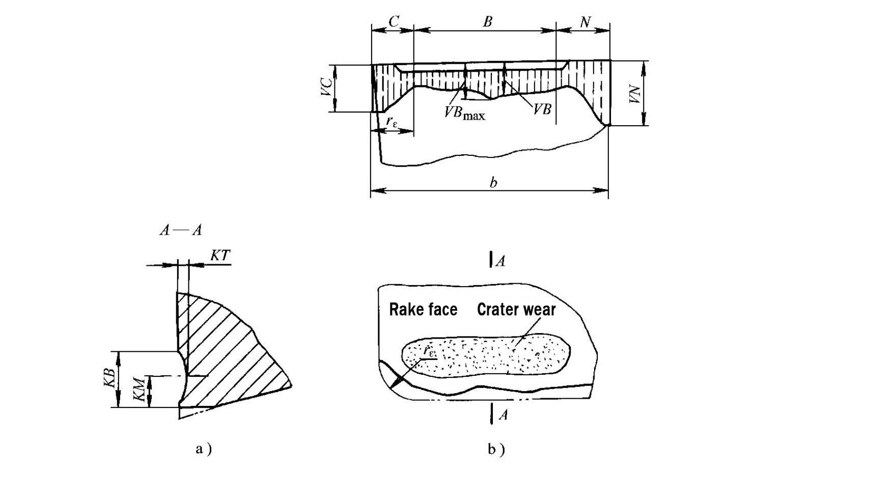
1.2Flank Face Wear:
Strong friction occurs between the flank face of the metal cutting tool and the machined surface, quickly forming a narrow wear land with zero clearance angle near the main cutting edge.
This type of wear occurs at low cutting speeds and small cutting thicknesses, regardless of whether brittle or ductile metals are being machined.
Typical flank wear band characteristics:
- Tool nose area (Zone C): Experiences the most severe wear due to low strength and poor heat dissipation; maximum value expressed as \(V_C\).
- Flank face near the workpiece surface (Zone N): Prone to deep grooves (boundary wear); depth represented by \(V_N\).
- Middle section of wear band (Zone B): Shows relatively uniform wear; maximum wear width denoted as \(V_{B\text{max}}\).
1.3Simultaneous Rake and Flank Wear:
When machining high-melting-point ductile metals under moderate cutting speeds and feed rates, crater wear on the rake face and wear on the flank face often occur simultaneously.
2.0What Is the Wear Process of Metal Cutting Tools?
Wear stage division:
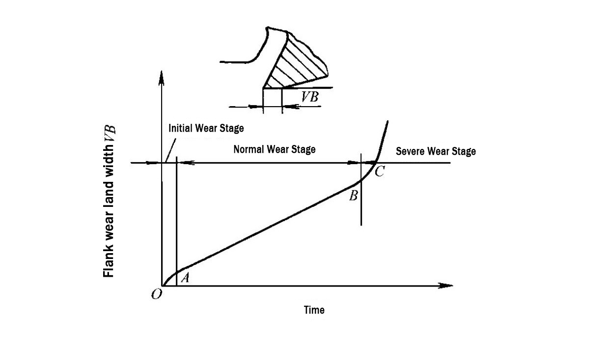
Under given cutting conditions, regardless of the wear form, tool wear increases with cutting time and generally progresses through three stages.
2.1Initial Wear Stage:
Newly ground metal cutting tools have rough surfaces and microscopic defects such as micro-cracks on the flank face. The cutting edge is sharp, and the contact area between the flank face and the machined surface is small.
As a result, compressive stress and cutting temperature are highly concentrated at the cutting edge, leading to a relatively high wear rate.
2.2Normal Wear Stage:
After the initial wear period, the rough surface of the flank face becomes smoother, the load-bearing area increases, compressive stress decreases, and the wear rate drops significantly and stabilizes. The metal cutting tool then enters the normal wear stage.
2.3Severe Wear Stage:
When the flank wear width \(V_B\) reaches a critical limit, friction increases sharply, cutting forces and cutting temperature rise rapidly, and the wear rate accelerates dramatically. The metal cutting tool quickly fails and loses its cutting capability.
3.0What Is the Tool Wear (Dulling) Criterion for Metal Cutting Tools?
Dulling judgment basis:
When a metal cutting tool wears to a certain extent, the following phenomena occur:
- Cutting force and cutting temperature increase significantly
- The machined surface becomes rough, and dimensional accuracy goes out of tolerance
- Chip color and shape become abnormal, with possible vibration or noise
These phenomena indicate that the tool has become dull.
Dulling criterion definition:
A maximum allowable wear value must be specified according to machining requirements—this value is known as the tool wear (dulling) criterion.
Criterion selection reason:
Since flank face wear is the most common and easiest to measure, the average wear value on the middle section of the flank face, \(V_B\), is typically used as the wear criterion for metal cutting tools.
3.1Recommended \(V_B\) Values Under Different Machining Conditions
| Machining Conditions | Recommended VB Value (mm) |
|---|---|
| Finish turning | 0.1–0.3 |
| Rough turning of alloy steel, or rough turning of low-rigidity workpieces | 0.4–0.5 |
| Rough turning of carbon steel | 0.6–0.8 |
| Rough turning of cast iron parts | 0.8–1.2 |
| Low-speed rough turning of large steel and cast iron workpieces | 1.0–1.5 |
4.0What Is the Tool Life of Metal Cutting Tools?
Tool life definition:
Tool life refers to the total effective cutting time from the start of cutting after tool grinding until the wear reaches the specified dulling criterion. Non-cutting times such as tool setting, measurement, rapid traverse, and return strokes are not included.
Tool life is denoted by \(T\) and measured in minutes.
Tool life classification:
- Regrindable metal cutting tools: Tool life refers to the actual cutting time between two consecutive regrinding operations; total tool life is the cutting time from first use until complete scrapping.
- Non-regrindable metal cutting tools: Total tool life is equal to the tool life.
5.0What Factors Affect the Tool Life of Metal Cutting Tools?
5.1Cutting Parameters:
Cutting parameters are among the most important influencing factors. The general relationship between tool life \(T\) and cutting parameters is:
$$
T = \frac{C_T}{v_c^x \cdot f^y \cdot a_p^z}
$$
Where:
- \(C_T\): Tool life constant related to tool material, workpiece material, and cutting conditions
- \(x, y, z\): Empirical exponents, typically with \(x > y > z\)
Example:
When turning carbon steel with \(\sigma_b = 0.637\ \text{GPa}\) using a carbide turning tool:
$$
T = \frac{C_T}{v_c^5 \cdot f^{2.25} \cdot a_p^{0.75}}
$$
Rule:
As\(v_c\), \(f\), and \(a_p\) increase, tool life \(T\) decreases. Cutting speed \(v_c\) has the greatest influence, followed by feed rate \(f\), and depth of cut \(a_p\) the least.
To improve productivity while ensuring tool life, select a larger \(a_p\) first, then a larger \(f\), and finally a reasonable\(v_c\).
5.2Tool Geometry Parameters:
- Rake angle (\(\gamma_o\)): Increasing it reduces cutting force and temperature, improving tool life. Excessive rake angle weakens tool strength and heat dissipation, increasing breakage risk.
- Principal cutting edge angle (\(\kappa_r\)): Reducing it enhances tool tip strength and heat dissipation. Excessively small \(\kappa_r\) increases radial force and may cause vibration in low-rigidity systems.
- Additional factors: Reducing minor cutting edge angle \(\kappa_r\) and increasing tool nose radius \(r_\varepsilon\) have similar positive effects on tool life.
5.3Tool Material:
Higher high-temperature strength and wear resistance extend tool life. In impact, heavy-duty, or difficult-to-machine conditions, impact toughness and bending strength become dominant factors.
5.4Workpiece Material:
- Higher strength and hardness increase cutting temperature and reduce tool life
- Greater plasticity and toughness combined with low thermal conductivity also raise cutting temperature and shorten tool life
6.0How to Reasonably Determine the Tool Life of Metal Cutting Tools?
Core principle:
A reasonable tool life selection improves productivity and reduces cost. Excessively long tool life requires small cutting parameters and lowers the metal removal rate. Excessively short tool life increases tool change and regrinding time, raising overall cost.
6.1Recommended Tool Life Values for Common Tools
| Tool Type | Recommended Tool Life (min) |
|---|---|
| High-speed steel turning tools | 60–90 |
| High-speed steel drills | 80–120 |
| Brazed carbide turning tools | 60 |
| Indexable carbide turning tools | 15–30 |
| Carbide face milling cutters | 120–180 |
| Gear cutting tools | 200–300 |
| High-speed steel turning tools for automatic machines | 180–200 |
6.2Additional Considerations:
- Tool complexity and precision: Complex, high-precision, multi-edge tools require longer life than simple, low-precision, single-edge tools.
- Indexable tools: Fast insert replacement allows shorter tool life to maintain sharp cutting edges.
- Finishing vs. roughing: Finishing tools require longer life due to lighter cutting loads and higher accuracy requirements.
- Finishing large workpieces: Longer tool life avoids mid-process tool changes.
- CNC machining: Tool life should exceed one work shift and be longer than the cutting time for a single part.
7.0Frequently Asked Questions (FAQ)
Q: Why is flank face wear the most commonly used tool dulling criterion?
A: Flank face wear is the most prevalent wear form in metal cutting, applicable to both brittle and ductile metals under low to medium cutting speeds. Its wear band has a regular shape, with uniform wear in the middle section (Zone B), and the average wear value \(V_B\) is easy to measure and control. Therefore,\(V_B\) is widely adopted as the standard dulling criterion.
Q: Which cutting parameter has the greatest influence on tool life?
A: Cutting speed (\(v_c\)) has the greatest influence, followed by feed rate (\(f\)), while depth of cut (\(a_p\) has the least effect). This is confirmed by the tool life equation, where larger exponents indicate greater impact.
Q: How does tool life selection differ between finishing and roughing operations?
A: Finishing operations involve lighter cutting loads and require longer tool life to ensure surface quality and dimensional accuracy. Roughing operations focus on rapid material removal and can use shorter tool life with larger cutting parameters.
Q: Why can indexable tools use shorter tool life than brazed tools?
A: Indexable tools allow fast insert replacement without regrinding, keeping cutting edges sharp. Shorter tool life enables higher cutting efficiency while balancing tooling cost.
Q: Are there special tool life requirements in CNC machining?
A: Yes. CNC machining is typically automated and continuous. Tool life should exceed one work shift and be longer than the cutting time required for a single part to ensure stable and uninterrupted production.