
In machining operations, cutting tools are directly involved in the material removal process, responsible for cutting away excess metal from the workpiece. The selection of tool type, structure, material, and geometric parameters depends heavily on the workpiece characteristics and machine tool configuration. These choices are critical to ensuring machining accuracy, efficiency, and overall process stability.
1.0What Types of Metal Cutting Tools Are There?
Based on differences in machining purpose and processing methods, metal cutting tools can be classified into the following seven major categories. Each category is specifically designed to suit particular machining scenarios:
- Turning and Cutting Tools: Includes turning tools (commonly used on conventional lathes and CNC lathes), planing tools (dedicated to shaper machines), slotting tools, boring tools, form turning tools, and various special-purpose cutting tools. These tools are mainly used for straight-line cutting, contour machining, and basic material removal operations.
- Hole-Making Tools: Covers tools used to create holes in solid materials as well as to refine existing holes, such as drills (commonly used on radial drilling machines) and reamers (typically applied on machining centers). These tools are essential for producing accurate and high-quality hole features.
- Broaching Tools: Designed for machining various shaped through-holes, flat surfaces, and formed profiles. Broaches are multi-tooth, high-productivity tools usually used in conjunction with horizontal broaching machines, making them ideal for mass production environments.
- Milling Cutters: Used for machining flat surfaces, side faces, stepped surfaces, formed surfaces, as well as for cutting-off and slotting operations. Common examples include face mills, form milling cutters, and keyway cutters, offering both high efficiency and machining flexibility.
- Thread Cutting Tools: Applied for machining internal and external threads, including thread turning tools, taps, and dies (commonly used on thread rolling machines). These tools play a decisive role in determining the accuracy and reliability of threaded connections.
- Gear Cutting Tools: Specifically developed for machining involute gears and other non-involute gear profiles, such as gear hobs, worm hobs, and spline hobs. These are specialized tools essential for precision gear manufacturing.
- Abrasive Tools: Includes grinding wheels (commonly used on surface grinders), abrasive belts, oil stones, and polishing wheels. These tools are used for surface finishing operations to improve surface roughness, dimensional accuracy, and overall part quality.
2.0How Are the Geometric Parameters of Metal Cutting Tools Defined and Applied?
Tool geometry is a decisive factor in cutting performance. Its definition and application must be based on a unified reference system. The following explanation is structured from three aspects: component elements, geometric angles, and working angles.
2.1What Are the Component Elements of the Cutting Part of a Tool?
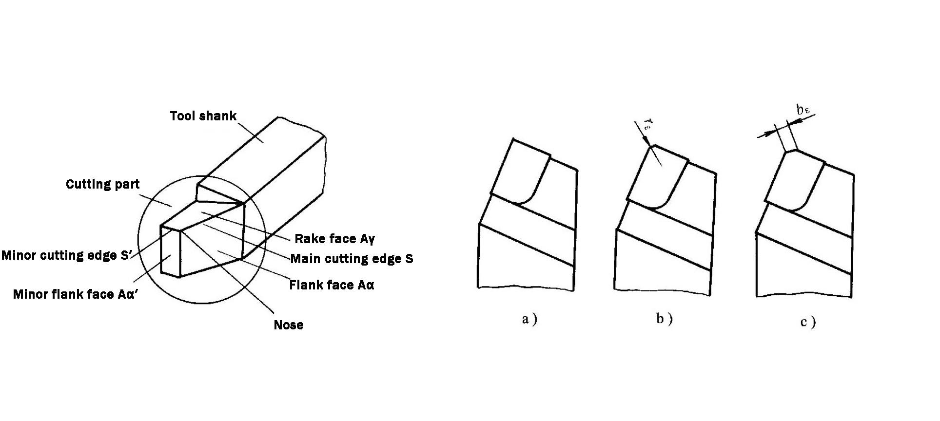
Although cutting tools vary widely in type and structure, the basic composition of their cutting parts is essentially consistent. Taking a standard external turning tool as an example, the core elements of its cutting part are as follows (see Fig. 1-19):
- Rake Face (Aᵧ): The surface over which chips flow during cutting. It directly affects chip evacuation efficiency and cutting performance.
- Flank Face (Aᵣ): The surface facing the transitional surface of the workpiece. Its geometry influences cutting friction and heat generation.
- Auxiliary Flank Face (Aᵣ′): The surface facing the already machined surface of the workpiece, mainly responsible for ensuring surface quality.
- Main Cutting Edge (S): The intersection line between the rake face and the flank face. It forms the transitional surface and undertakes the primary material removal task.
- Auxiliary Cutting Edge (S′): The intersection line between the rake face and the auxiliary flank face. It works together with the main cutting edge to remove material and finally shape the machined surface.
- Tool Nose: The small cutting edge at the junction of the main and auxiliary cutting edges. It can be a rounded nose or a chamfered nose (see Fig. 1-20) and has a direct impact on cutting stability and surface finish.
2.2How Are the Geometric Angles of the Cutting Part Classified and Measured?
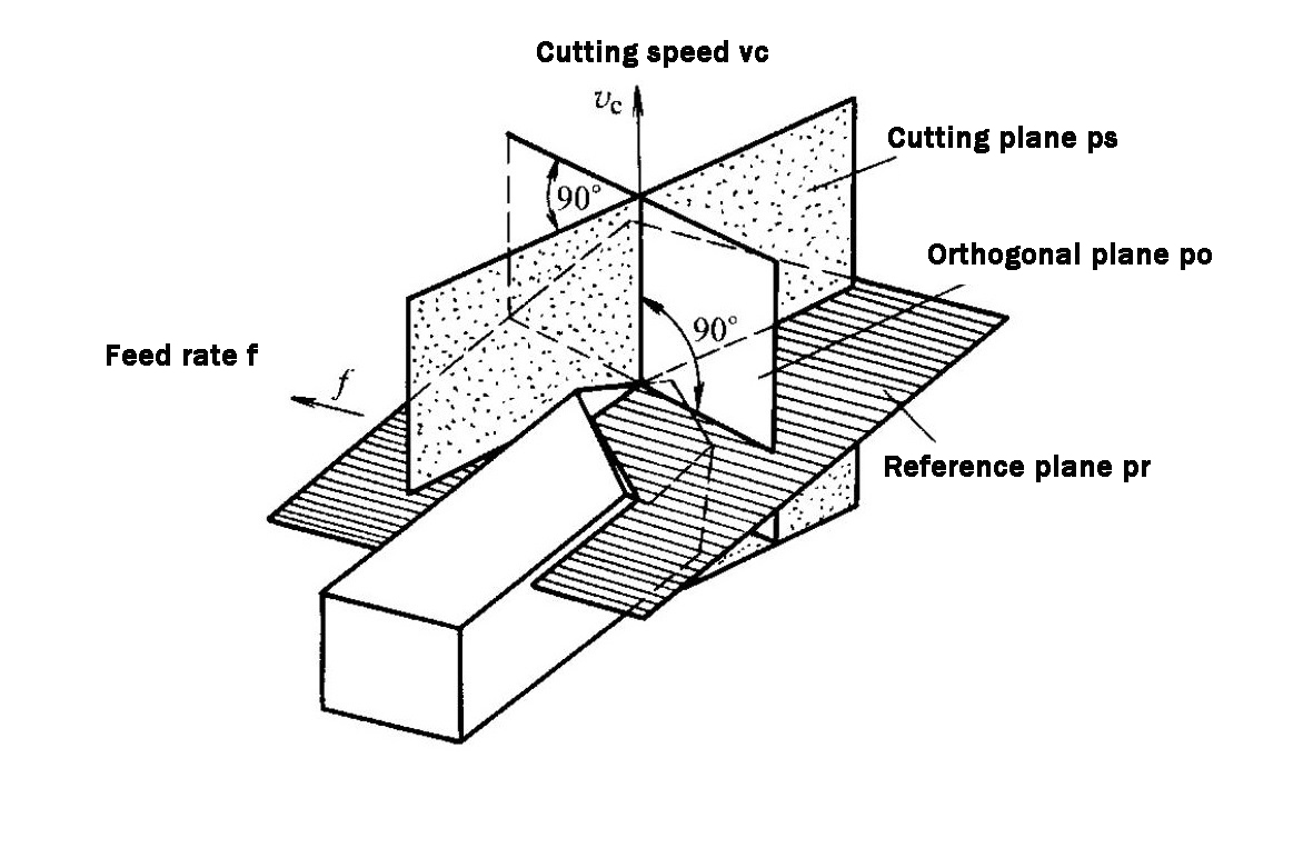
The definition of tool geometric parameters is based on reference coordinate systems and reference planes. The tool-in-rest reference system is the fundamental basis for tool design, manufacturing, sharpening, and measurement. Angles defined in this system are referred to as designated (nominal) angles. Below is an overview of the commonly used orthogonal reference plane system and its associated angles.
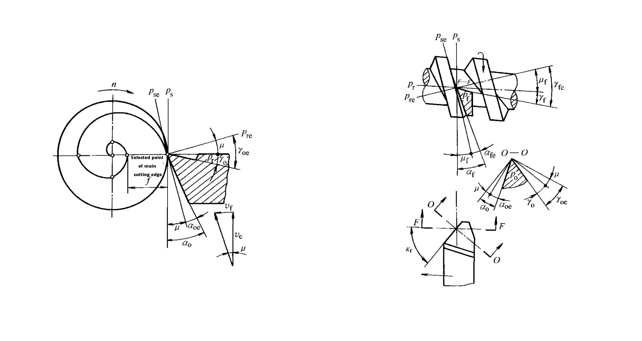
Composition of the Orthogonal Reference Plane System (see Fig. 1-21)
- Base Plane (Pᵣ): A plane passing through the selected point on the cutting edge and perpendicular to the main cutting motion direction. For turning and planing tools, it is parallel to the tool shank mounting plane; for rotating tools such as drills and milling cutters, it passes through the tool axis.
- Cutting Plane (Pₛ): A plane passing through the selected point on the cutting edge, tangent to the cutting edge and perpendicular to the base plane. For straight-edged tools, it contains the cutting edge and is perpendicular to the base plane.
- Orthogonal Plane (Pₒ): A plane passing through the selected point on the cutting edge and perpendicular to both the base plane and the cutting plane. It can also be regarded as the plane perpendicular to the projection of the cutting edge on the base plane.
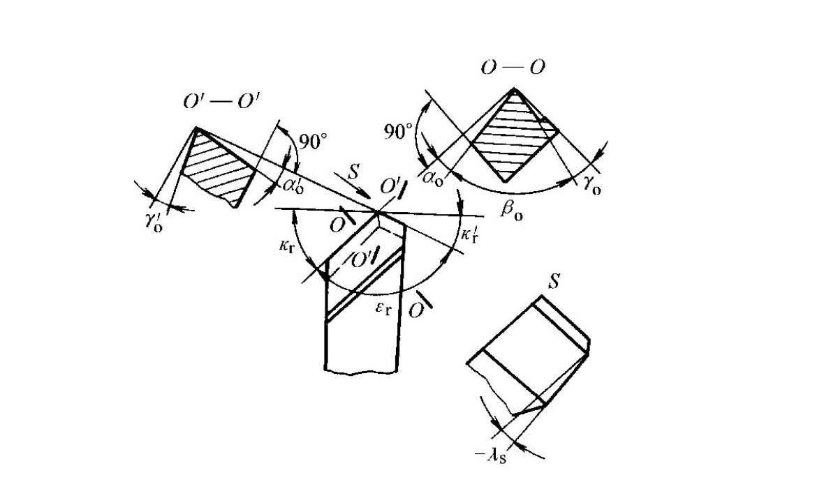
Classification and Definition of Designated Tool Angles (see Fig. 1-22)
Designated angles are measured in different reference planes and are defined as follows:
Angles measured in the orthogonal plane
- Rake Angle (γₒ): The angle between the rake face and the base plane. It is positive when the angle between the rake face and the cutting plane is less than 90°, and negative when greater than 90°. This angle has a significant influence on cutting performance.
- Clearance Angle (αₒ): The angle between the flank face and the cutting plane. It is positive when the angle between the flank face and the base plane is less than 90°, and negative when greater than 90°. Its main function is to reduce friction between the flank face and the transitional surface.
- Wedge Angle (βₒ): The angle between the rake face and the flank face. It is a derived angle, calculated as:βₒ = 90° − (γₒ + αₒ) (Equation 1-1).
Angles measured in the base plane
- Main Cutting Edge Angle (κᵣ): The angle between the main cutting plane and the assumed feed direction. It is always a positive value.
- Auxiliary Cutting Edge Angle (κᵣ′): The angle between the auxiliary cutting plane and the assumed opposite feed direction.
- Nose Angle (εᵣ): The angle between the main cutting plane and the auxiliary cutting plane. It is a derived angle, calculated as:εᵣ = 180° − (κᵣ + κᵣ′) (Equation 1-2).
Angle measured in the cutting plane
- Inclination Angle (λₛ): The angle between the main cutting edge and the base plane. It is positive when the tool nose is higher than the tool shank mounting plane, negative when lower, and 0° when parallel (cutting edge lies in the base plane).
Angle measured in the auxiliary orthogonal plane
- Auxiliary Clearance Angle (αₒ′): The angle between the auxiliary flank face and the auxiliary cutting plane. It is positive when the angle between the auxiliary flank face and the base plane is less than 90°, and negative when greater than 90°. This angle determines the position of the auxiliary flank face.
2.3What Factors Affect the Working Angles of a Cutting Tool?
Designated angles represent idealized conditions. In actual machining, feed motion and tool installation alter the real cutting geometry, resulting in working angles. The main influencing factors are as follows:
Influence of Feed Motion
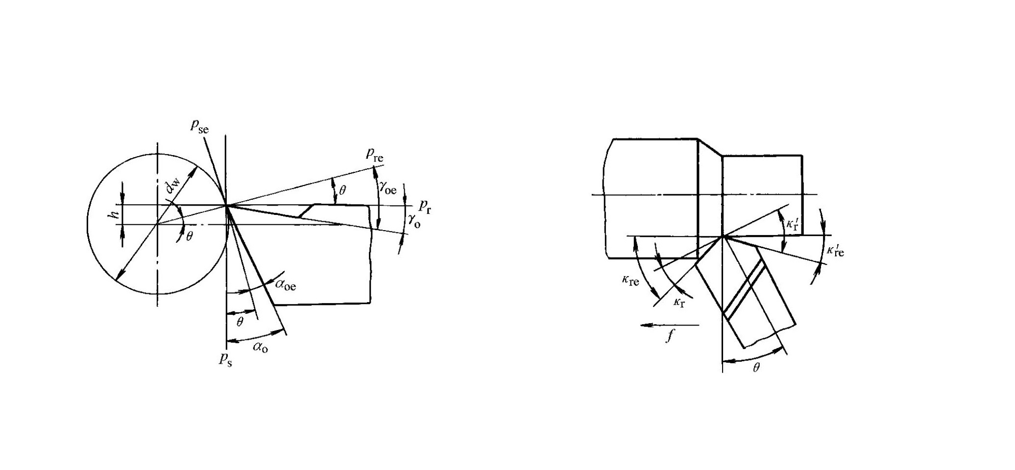
- Transverse Feed Motion (see Fig. 1-23): During parting-off or grooving on a lathe, the tool feeds transversely. The resultant motion direction forms an angle μ with the main motion direction. The working base plane (Pᵣₑ) and working cutting plane (Pₛₑ) rotate by μ relative to the base plane (Pᵣ) and cutting plane (Pₛ). The working rake and clearance angles are:γₒₑ = γₒ + μαₒₑ = αₒ − μ (Equation 1-3)where tan μ = f / (πd),f is the transverse feed per revolution (mm/r), and d is the instantaneous diameter at the selected cutting point (mm).As a result, the working rake angle increases while the working clearance angle decreases. Therefore, during transverse turning, αₒ should be appropriately increased to compensate for this effect.
- Longitudinal Feed Motion (see Fig. 1-24): In operations such as thread turning, the resultant motion direction forms an angle μᵦ with the main motion direction. The working rake and clearance angles change as:γᵦₑ = γᵦ + μᵦαᵦₑ = αᵦ − μᵦ (Equation 1-4)where tan μᵦ = f / (πdω),γᵦ and αᵦ are the rake and clearance angles measured in the F–F section, and dω is the workpiece diameter at the selected point (mm).A larger feed or smaller diameter increases the working rake angle and decreases the working clearance angle. Therefore, different clearance angles should be selected on both sides of the thread turning tool according to thread lead and helix direction.
Influence of Tool Installation Position
- Effect of Tool Height (see Fig. 1-25): Taking external turning as an example, neglecting feed motion and assuming λₛ = 0, when the cutting edge is positioned above the workpiece center, the working base and cutting planes rotate by an angle θ. The working angles become:γₒₑ = γₒ + θαₒₑ = αₒ − θ (Equation 1-5)where h is the height of the cutting edge above the workpiece center. When the cutting edge is below the center, the angle changes are opposite. In boring operations, the variation trend of working angles is opposite to that in external turning.
- Effect of Tool Shank Axis Not Perpendicular to Feed Direction (see Fig. 1-26): When the tool shank axis is inclined by an angle θ relative to the feed direction, the working cutting edge angles change as:κᵣₑ = κᵣ + θκᵣₑ′ = κᵣ′ − θ (Equation 1-6)
3.0How Should Metal Cutting Tool Materials Be Selected?
Cutting tool materials refer specifically to the materials used for the cutting portion of a tool. Their performance is the decisive factor in cutting effectiveness and must be selected scientifically based on machining requirements and workpiece characteristics.
3.1What Core Properties Should Cutting Tool Materials Have?
During cutting, the tool’s cutting edge is subjected to high temperatures, high pressures, friction, impact, and vibration. Therefore, cutting tool materials must meet the following key performance requirements:
- High hardness and wear resistance: Room-temperature hardness should be no less than 60 HRC. In general, higher hardness, higher carbide content, finer carbide particles, and more uniform distribution result in better wear resistance.
- Sufficient strength and toughness: Adequate bending strength and impact toughness are required to prevent tool breakage or edge chipping during machining.
- Good heat resistance and thermal conductivity: Heat resistance refers to the ability to retain hardness, wear resistance, strength, and toughness at elevated temperatures. Better thermal conductivity helps reduce cutting-zone temperature and slow down tool wear.
- Good manufacturability and economic efficiency: The material should offer good machinability, forgeability, heat-treatability, weldability, and grindability, while also providing a favorable cost–performance ratio.

3.2What Are the Common Types and Characteristics of Cutting Tool Materials?
Common cutting tool materials include carbon tool steel, alloy tool steel, high-speed steel (HSS), cemented carbide, and superhard materials. Among these, high-speed steel and cemented carbide are the most widely used.
High-Speed Steel (HSS)
High-speed steel is a high-alloy tool steel containing significant amounts of tungsten, chromium, molybdenum, vanadium, and other alloying elements. It features high strength, good impact toughness, and relatively high wear resistance and heat resistance, maintaining cutting capability at temperatures of 600–700 °C. HSS exhibits minimal heat-treatment deformation and is easy to forge and grind, making it a cutting tool material with excellent overall performance and broad application.It is particularly suitable for manufacturing complex cutting tools such as milling cutters, drills, hobs, and broaches. According to application requirements, high-speed steel can be divided into two main categories:
- General-purpose high-speed steel: Hardness typically ranges from 63 to 66 HRC. Cutting speeds when machining steel are generally limited to 50–60 m/min. It is not suitable for high-speed cutting or machining very hard materials. Common grades include W18Cr4V (good overall performance), W6Mo5Cr4V2 (higher strength, toughness, and hot workability than W18Cr4V, but slightly lower thermal stability), and W14Cr4VMn-RE (performance close to W18Cr4V).
- High-performance high-speed steel: Developed on the basis of general-purpose HSS by increasing carbon and vanadium content or by adding elements such as cobalt and aluminum. These steels can maintain a hardness of about 60 HRC at 630–650 °C, with tool life 1.5–3 times that of general-purpose HSS. They are suitable for machining difficult-to-cut materials such as austenitic stainless steels, high-temperature alloys, and titanium alloys. Common grades include high-carbon types (9W18Cr4V), high-vanadium types (W12Cr4V4Mo), and ultra-hard types (such as W6Mo5Cr4V2Al and W2Mo9Cr4VCo8). However, their overall performance is generally inferior to that of general-purpose HSS, and their application range is more restricted by cutting conditions.
Common grades and properties of high-speed steels are summarized in Table 1-3.
| Category | Grade | Hardness (HRC) | Bending Strength (GPa) | Impact Toughness (MJ·m⁻²) | Hot Hardness at 600 °C (HRC) | Grindability |
| General-purpose HSS | W18Cr4V | 62–66 | ≈3.34 | 0.294 | 48.5 | Good; can be ground with conventional alumina wheels |
| W6Mo5Cr4V2 | 62–66 | ≈4.6 | ≈0.5 | 47–48 | Slightly inferior to W18Cr4V; grindable with conventional alumina wheels | |
| W14Cr4VMn-RE | 64–66 | ≈4.0 | ≈0.25 | 48.5 | Good; comparable to W18Cr4V | |
| High-performance HSS | 9W18Cr4V (high-carbon) | 67–68 | ≈3.0 | ≈0.2 | 51 | Good; grindable with conventional alumina wheels |
| W12Cr4V4Mo (high-vanadium) | 63–66 | ≈3.2 | 0.25 | 51 | Poor | |
| W6Mo5Cr4V2Al (ultra-hard) | 68–69 | ≈3.43 | ≈0.3 | 55 | Slightly inferior to W18Cr4V | |
| W10Mo4Cr4V3Al | 68–69 | ≈3.0 | ≈0.25 | 54 | Relatively poor | |
| W6Mo5Cr4V5SiNbAl | 66–68 | ≈3.6 | ≈0.27 | 51 | Poor | |
| W12Cr4V3Mo3Co5Si | 69–70 | ≈2.5 | ≈0.11 | 54 | Poor | |
| W2Mo9Cr4VCo8 (M42) | 66–70 | ≈2.75 | ≈0.25 | 55 | Good; grindable with conventional alumina wheels |
Cemented Carbides
Cemented carbides are powder-metallurgy materials made from high-hardness, high-melting-point carbides (such as WC, TiC, TaC, and NbC) bonded with metallic binders including Co, Mo, or Ni. They exhibit a room-temperature hardness of 78–82 HRC and heat resistance of 800–1000 °C. Their allowable cutting speeds are typically 4–10 times higher than those of high-speed steel.Due to relatively lower impact toughness and bending strength, cemented carbides are usually brazed or mechanically clamped onto tool bodies. Common cemented carbides are classified into three main categories:
- Tungsten–cobalt carbides (YG): Composed of WC and Co, offering good toughness but slightly lower hardness and wear resistance. Suitable for machining brittle materials such as cast iron. Higher Co content improves toughness. Typical grades include YG8 (roughing), YG6 (semi-finishing), and YG3 (finishing), where the numerical value indicates cobalt content.
- Tungsten–titanium–cobalt carbides (YT): Composed of WC, TiC, and Co, featuring good heat resistance and wear resistance but relatively poor impact toughness. Suitable for machining ductile materials such as steels. Higher TiC content increases wear resistance but reduces toughness. Common grades include YT5 (roughing), YT15 (semi-finishing), and YT30 (finishing).
- Tungsten–titanium–tantalum (niobium) carbides (YW): Produced by adding TaC or NbC to YT-type carbides, combining the advantages of both YG and YT types. Suitable for machining steel, cast iron, non-ferrous metals, high-temperature alloys, and other difficult-to-machine materials. Common grades include YW1 and YW2.
YG, YT, and YW carbides correspond respectively to ISO classes K, P, and M. Their grades, properties, and applications are summarized in Table 1-4.
| Type | Grade | Hardness (HRA) | Hardness (HRC) | Bending Strength (GPa) | Wear Resistance | Impact Resistance | Heat Resistance | Applicable Materials | Machining Characteristics |
| Tungsten–cobalt | YG3 | 91 | 78 | 1.08 | – | – | – | Cast iron, non-ferrous metals | Continuous cutting, finishing and semi-finishing |
| YG6X | 91 | 78 | 1.37 | – | – | – | Cast iron, heat-resistant alloys | Finishing and semi-finishing | |
| YG6 | 89.5 | 75 | 1.42 | – | – | – | Cast iron, non-ferrous metals | Continuous roughing; intermittent semi-finishing | |
| YG8 | 89 | 74 | 1.47 | – | – | – | Cast iron, non-ferrous metals | Intermittent roughing | |
| Tungsten–titanium–cobalt | YT5 | 89.5 | 75 | 1.37 | – | – | – | Steel | Rough machining |
| YT14 | 90.5 | 77 | 1.25 | – | – | – | Steel | Intermittent semi-finishing | |
| YT15 | 91 | 78 | 1.13 | – | – | – | Steel | Continuous roughing; intermittent semi-finishing | |
| YT30 | 92.5 | 81 | 0.88 | – | – | – | Steel | Continuous finishing | |
| Carbides with rare-metal additions | YA6 | 92 | 80 | 1.37 | Good | – | – | Chilled cast iron, non-ferrous metals, alloy steels | Semi-finishing |
| YW1 | 92 | 80 | 1.28 | – | Good | Good | Difficult-to-machine steels | Finishing and semi-finishing | |
| YW2 | 91 | 78 | 1.47 | – | Good | – | Difficult-to-machine steels | Semi-finishing and roughing | |
| Nickel–molybdenum–titanium | YN10 | 92.5 | 81 | 1.08 | Good | – | Good | Steel | Continuous finishing |
3.3What Are the Application Scenarios for Other Special Cutting Tool Materials?
In addition to commonly used tool materials, the following special cutting tool materials are designed for specific high-end machining requirements:
- Coated Tool Materials: Thin layers of refractory metal compounds such as TiC, TiN, and Al₂O₃ are deposited onto high-speed steel or cemented carbide substrates using CVD (Chemical Vapor Deposition) or PVD (Physical Vapor Deposition) processes. These tools combine the strength and toughness of the substrate with the superior wear resistance of the coating. TiC coatings emphasize hardness and wear resistance, TiN coatings offer enhanced oxidation resistance and anti-adhesion properties, while Al₂O₃ coatings provide excellent thermal stability. The coating type can be selected according to specific machining needs.
- Ceramics: Primarily composed of Al₂O₃, ceramic cutting tools typically have a hardness of ≥78 HRC and can withstand temperatures of 1200–1450 °C. They support very high cutting speeds but have relatively low bending strength and poor impact resistance. Ceramic tools are suitable for finishing operations on steel, cast iron, high-hardness materials, and high-precision components.
- Diamond: Mainly in the form of synthetic diamond, these tools exhibit extremely high hardness (approximately 10,000 HV, compared with 1300–1800 HV for cemented carbide). Their wear resistance is 80–120 times that of cemented carbide. However, diamond tools have low toughness and strong chemical affinity with ferrous materials, making them unsuitable for machining ferrous metals. They are primarily used for high-speed precision finishing of non-ferrous metals and non-metallic materials.
- Cubic Boron Nitride (CBN): CBN is a synthetic superhard material with a hardness of approximately 7,300–9,000 HV and a heat resistance of 1,300–1,500 °C. It exhibits low chemical affinity with ferrous elements, but has relatively low strength and poor brazability. CBN tools are mainly used for machining hardened steels, chilled cast iron, high-temperature alloys, and other difficult-to-machine materials.
4.0FAQ: Frequently Asked Questions About Metal Cutting Tools
Q1: How do I choose the right cutting tool for my machining operation?
A: Selection depends on the workpiece material, machining process, and machine tool type. Turning tools are used for lathes, milling cutters for milling machines, drills for drilling machines, and broaches for horizontal broaching machines. Tool geometry and material must match the cutting conditions for optimal performance.
Q2: What is the difference between designated angles and working angles?
A: Designated angles are ideal angles defined for tool design and measurement under static conditions. Working angles are the actual angles during machining, influenced by feed motion, tool installation height, and tool inclination. Proper adjustment ensures stable cutting and surface quality.
Q3: How do rake angle and clearance angle affect cutting performance?
A: The rake angle (γₒ) controls chip flow and cutting resistance, while the clearance angle (αₒ) reduces friction between the flank face and workpiece surface. Selecting appropriate angles improves tool life, reduces heat, and ensures dimensional accuracy.
Q4: Which cemented carbide classes are suitable for different materials?
A: K-class (YG): brittle materials like cast iron. P-class (YT): ductile materials like steel. M-class (YW): steels, cast iron, and difficult-to-machine materials such as high-temperature alloys.
Q5: Why are diamond cutting tools unsuitable for ferrous metals?
A: Diamond reacts chemically with iron, causing accelerated tool wear. Diamond tools are ideal for non-ferrous metals, plastics, and composites requiring high-speed precision finishing.
Q6: When should coated, ceramic, or CBN tools be used?
A: Coated tools (TiN, TiC, Al₂O₃) for enhanced wear resistance and thermal stability. Ceramic tools for high-speed finishing of steels, cast iron, and hard materials. CBN tools for hardened steels and high-temperature alloys.
Q7: How does feed motion and tool height affect working angles?
A: Transverse or longitudinal feed changes the effective rake and clearance angles. Tool height above or below the workpiece center also modifies the working angles. Correct compensation ensures consistent surface finish and cutting efficiency.
Reference
https://en.wikipedia.org/wiki/Rake_angle
https://www.researchgate.net/figure/Schematic-of-the-cutting-part-of-the-tool-with-the-auxiliary-cutting-edge-on-the-flank_fig2_312420371