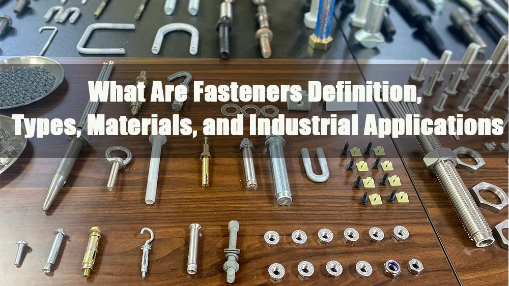
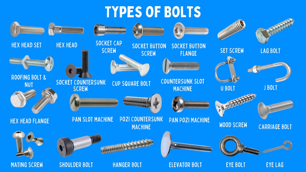
- 1.0Definition and Core Types of Fasteners
- 2.0Key Terminology Explained
- 3.0Thread Type Selection: Application Logic of Coarse and Fine Threads
- 4.0Thread Manufacturing Processes: Rolled vs. Cut Threads (Key Equipment: Thread Rolling Machine)
- 5.0Core Function and Application Restrictions of Fasteners
- 6.0Preload Control: Risks of Over-Tightening and Under-Tightening
- 7.0Fastener Preload and Torque Calculation (with Practical Verification)
- 8.0Fastener Selection and Identification Standards
- 9.0Fastener Hole Design: Tap Drill Holes and Clearance Holes
- 10.0Fastener Joint Design: Enhancing Stability and Strength
- 11.0Conclusion
In the global machinery and equipment industry, fasteners are fundamental components that connect individual parts. Their design, selection, and installation directly affect the reliability and service life of mechanical systems.Industry data shows that failures caused by improper design, incorrect selection, or installation errors are among the main reasons for mechanical malfunctions. From general machinery assembly to high-precision systems such as aerospace and automotive components, the proper use of fasteners is essential.
1.0Definition and Core Types of Fasteners
1.1Definition
A fastener is a standardized hardware component used to join two or more parts together. It allows for quick installation and removal through manual or powered tools (such as torque wrenches) or automated equipment (like fastener insertion machines). The key features of fasteners are removability and connection stability, distinguishing them from semi-permanent joining methods such as welding or riveting. Fasteners are widely used across industries including automotive, aerospace, and electronics.
1.2Core Types
Based on thread characteristics and application methods, fasteners are categorized into three main types, often paired with automated equipment (e.g., press-in machines) for mass production efficiency:
| Fastener Category | Common Types | Key Application Features | Automation Compatibility |
| External-thread (Male) | Hex head bolts, flat head screws, socket head cap screws, round head screws, set screws | Connect via external threads; bolts pair with nuts; screws thread directly into workpieces | Press-in machines install self-clinching variants (no tapping needed) |
| Internal-thread (Female) | Standard hex nuts (ISO 4032), nylon insert lock nuts (ISO 10511) | Form detachable joints with bolts/studs; prevent loosening (lock nuts) | Insertion machines install nuts synchronously with bolts for alignment |
| Special Types | Studs (ISO 888, double-ended threaded) | One end threads into workpieces; the other pairs with nuts; ideal for thick parts/frequent disassembly | Press-in machines ensure precise stud positioning in heavy machinery |
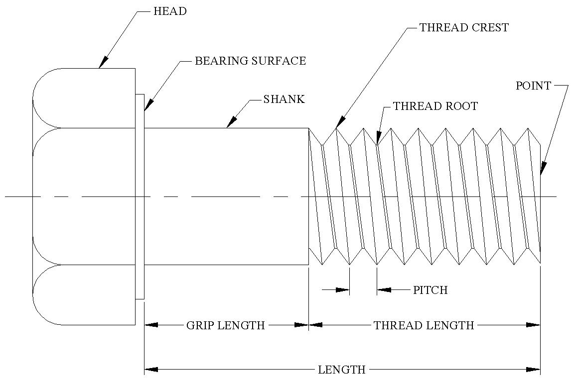
2.0Key Terminology Explained
Understanding fastener terminology is critical for accurate design and selection. Below are internationally recognized definitions (based on ISO standards):
| Term | Definition | Example/Note |
| Major Diameter | The largest diameter of a thread; serves as the nominal size reference. | An M10 bolt has a major diameter of 10 mm (ISO 898-1). |
| Minor Diameter | The smallest diameter of a thread; determines shear and tensile strength. | Critical for choosing coarse vs. fine threads. |
| Pitch | Axial distance between corresponding points on adjacent threads. | M10 coarse pitch = 1.5 mm; fine pitch = 1.0 mm (ISO 724). |
| Lead | Axial distance a thread advances in one revolution. | Single-start threads: Lead = Pitch; multi-start threads: Lead = Pitch × Number of starts. |
| Thread Crest/Root | Crest = Top surface (farthest from reference cylinder); Root = Bottom surface (stress concentration zone). | Rolled threads optimize root curvature to improve fatigue resistance. |
| Shank | Cylindrical portion between the head and thread start; designed for shear loads. | Threads must never bear shear; press-in machines keep shanks in shear planes. |
| Preload | Tensile force applied when tightening; ensures joint stability. | Insertion machines with torque control apply accurate preload (no reliance on lock washers alone). |
| Grip Length | Unthreaded portion between head bearing surface and thread start. | Must match total thickness of jointed parts; press-in machine tests verify fit. |
3.0Thread Type Selection: Application Logic of Coarse and Fine Threads
Fastener threads follow ISO standards (metric: ISO 724; imperial: ANSI/ASME B1.1) and are selected based on material strength matching:
| Thread Type | Suitable Scenarios (Material Pairing) | Key Advantages | Automation Compatibility |
| Fine Thread | Internal thread material > External thread material (e.g., steel screws into high-strength alloys) | Higher static/fatigue strength; precise preload control; ideal for high-precision applications (aerospace, precision instruments) | Insertion machines fine-tune rotation speed to avoid cross-threading. |
| Coarse Thread | Internal thread material < External thread material (e.g., steel bolts into aluminum/cast iron) | Larger minor diameter (reduces tensile failure risk); faster assembly; suitable for general machinery | Press-in machines quickly install self-clinching nuts (no tapping needed). |
3.1Common Misconceptions
- Myth: Coarse threads are always stronger.
- Fact: Strength depends on material pairing:
- Fine threads in weak materials (e.g., aluminum) cause thread stripping.
- Coarse threads in strong materials (e.g., steel) waste strength and reduce preload accuracy.
- Example: Automotive engine assemblies (cast iron blocks + aluminum heads) use coarse-thread bolts, tightened by automated insertion systems to balance strength and efficiency.
4.0Thread Manufacturing Processes: Rolled vs. Cut Threads (Key Equipment: Thread Rolling Machine)
Thread processing directly impacts fastener performance. High-quality fasteners globally use rolled threads (ISO 898-6) over traditional cut threads, with the thread rolling machine as core equipment:
| Process Aspect | Cut Threads | Rolled Threads (via Thread Rolling Machine) |
| Formation Principle | Material removal (lathes, taps, dies) | Plastic deformation (radial pressure from rolling dies; no material removed) |
| Grain Flow | Interrupted (weakens structure) | Continuous (follows thread contour; increases density) |
| Surface Roughness | Ra ≥ 6.3 μm (rough; prone to wear) | Ra ≤ 1.6 μm (smooth; reduces friction) |
| Fatigue Strength | Lower (stress concentration at roots) | 50–75% higher; 5–10× longer life for HRC 36–40 fasteners (ISO 898-1 tests) |
| Production Efficiency | Slow (20–50 pieces/min; lathes) | Fast (100–500 pieces/min; high-speed rolling machines) |
| Cost | Higher (cutting fluid use; short tool life) | 20–40% lower (dry processing; long die life: tens of thousands of parts) |
| Assembly Compatibility | Low dimensional consistency (causes insertion machine jamming; chip scratches) | ISO 4H/5g tolerance; ≤0.1 mm concentricity (ensures tight nut engagement and consistent preload). |
5.0Core Function and Application Restrictions of Fasteners
5.1Sole Core Function: Clamping Connection
Fasteners exist to clamp components via preload (not for positioning, load-bearing, or transmission):
| Function Type | Correct Implementation | Risk of Misuse (Using Fasteners) |
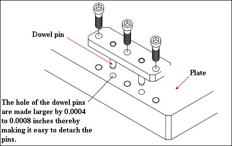
| Positioning | Use dowel pins (ISO 2338), locating shoulders, or reference surfaces. | Thread clearance causes component misalignment, vibration, and wear. |
| Load-Bearing/Transmission | Use dedicated pins (ISO 8734) or bearings for shafts/pivots/axles. | Fastener bending/impact failure (e.g., bolts as conveyor roller shafts break quickly). |
| Example | Automotive transmission: Dowel pins locate the housing; insertion machines tighten bolts. | Conveyor rollers: Dedicated axles + bolts (installed via press-in machines) clamp end covers. |
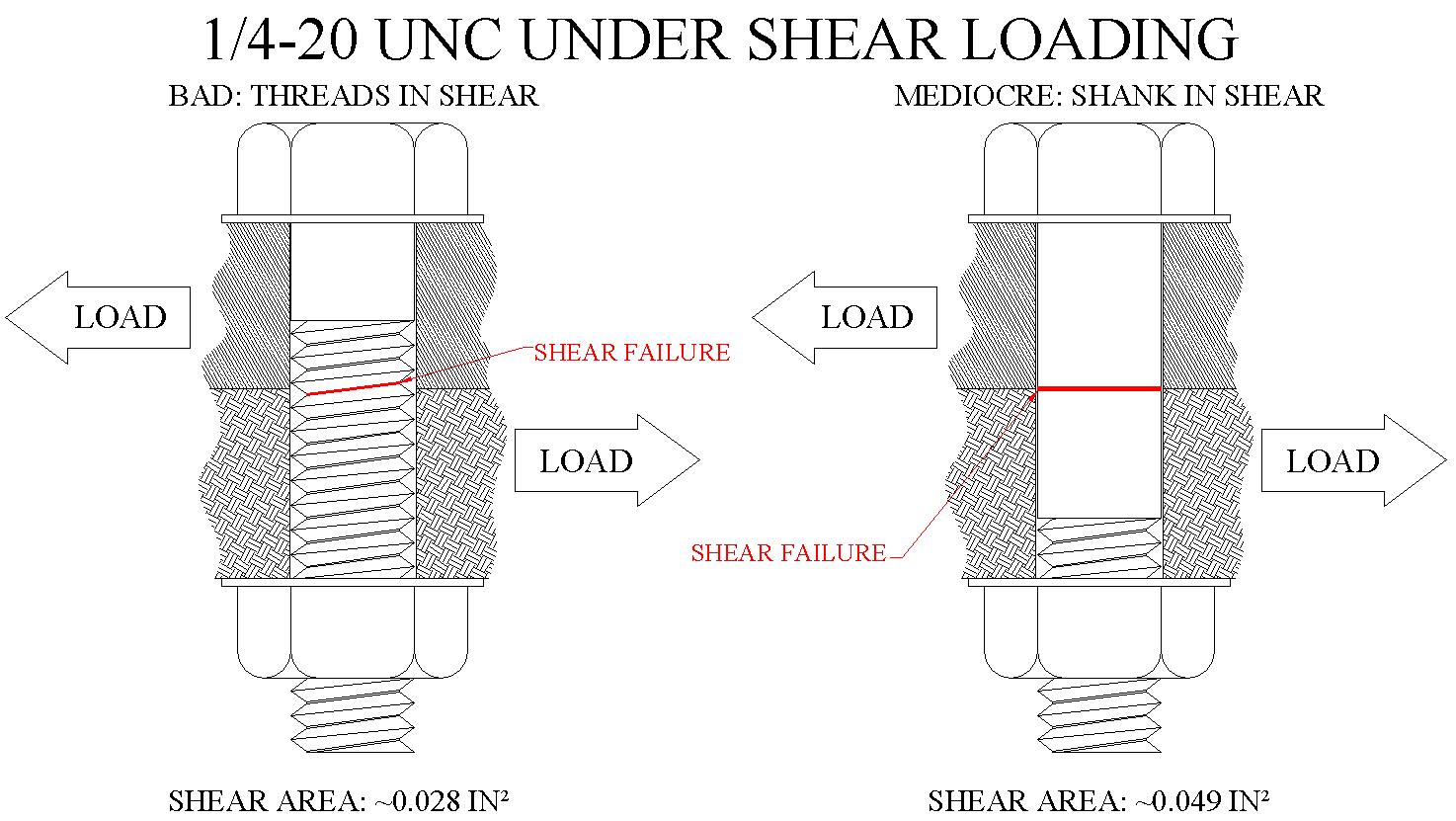
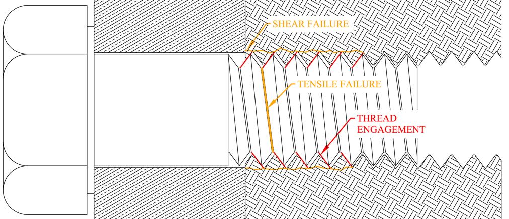
5.2Critical Application Restriction: No Shear Load on Threads
Threads are the weakest fastener part—never subject them to shear. Key reasons:
- Thread minor diameter < shank diameter (only 60–80% of shank shear strength).
- Limited thread-hole contact area (reduces stability; causes loosening).
- Loosened threads abrade hole walls (enlarges clearance; accelerates failure).
Correct Practice:
- Use dowel pins to bear shear loads.
- Position the shank (unthreaded portion) in the shear plane (e.g., double-shear joints).
- Sheet metal applications: Press-in bolts keep threads outside shear zones; insertion machines control tightening depth for optimal shank placement.
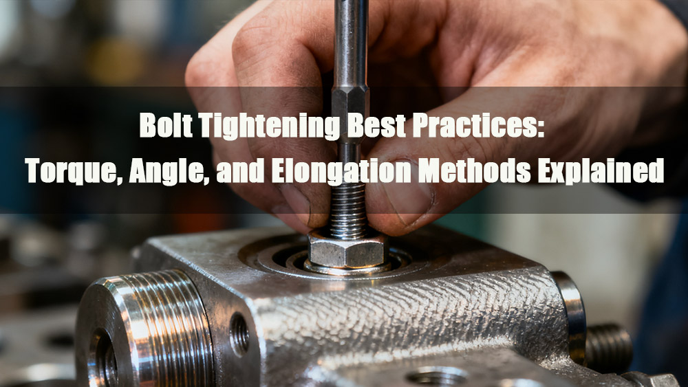
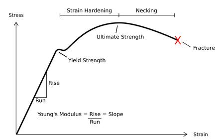
6.0Preload Control: Risks of Over-Tightening and Under-Tightening
Preload is critical for joint stability. Over-tightening (within yield limit) is safer than under-tightening (based on ISO 6892-1 stress-strain behavior):
6.1Key Insights from the Stress-Strain Curve
Fastener materials (e.g., alloy steel, ISO 898-1) have three stages:
- Elastic Stage: Material returns to original shape; insufficient preload causes fatigue failure under cyclic loads (e.g., engine vibrations).
- Yield Stage: Permanent deformation begins; avoid exceeding yield strength.
- Strain-Hardening Stage: Preload near (but not above) yield improves stability and resists external loads.
6.2Common Misconceptions
- Myth: Lock washers, anaerobic adhesives, or safety wires replace preload.
- Fact: These only delay loosening (do not prevent it). Proper preload is the only guarantee of stability.
- Automation Solution: Insertion machines with torque sensors monitor preload in real time; manual assembly uses ISO 6789 torque wrenches (no “feel-based” tightening).
7.0Fastener Preload and Torque Calculation (with Practical Verification)
Preload is controlled via torque. Below is a globally accepted simplified method (±20% accuracy, ISO-derived):
7.1Core Formulas
- Tensile Stress for Preload: Avoid permanent deformation; use 90% of yield strength:\(\sigma_t \approx 0.9 \times \sigma_y\)(Example: ISO 898-1 Grade 8.8 bolt → \(\sigma_y = 640\) MPa)
- Preload Calculation:\(F_i = \sigma_t \times A_t\)(\(A_t\) = thread tensile stress area; e.g., M10 threads → \(A_t = 58.0\) mm², ISO 6560)
- Torque Calculation:\(T \approx 0.2 \times F_i \times d\)(d = nominal diameter; 0.2 = coefficient for \(\mu = 0.15\); adjust for lubrication/coatings per ISO 16047.)
7.2Example Calculation (M10 × 1.5, Grade 8.8 Bolt)
- From ISO 898-1:\(\sigma_y = 640\) MPa
- Tensile stress:\(\sigma_t = 0.9 \times 640 = 576\) MPa
- Tensile stress area:\(A_t = 58.0\) mm²
- Preload:\(F_i = 576 \times 58.0 = 33,408\) N ≈ 33.4 kN
- Torque:\(T = 0.2 \times 33,408 \times 10 = 66,816\) N·mm ≈ 66.8 N·m
7.3Experimental Verification (ISO 16047 Fatigue Test)
For a 3/8-inch bolt (180,000 psi tensile strength, ANSI/ASME B18.2.1):
| Preload Level (Tensile Strength %) | Torque | Load Cycles Under 12,000 lbf Alternating Load |
| 40% | ≈25 lbf·ft | ~4,900 |
| 60% | ≈37 lbf·ft | ~6,000,000 (1,000× increase) |
- Industry Application: Boeing’s fastener manuals require 70–80% yield preload, achieved via torque-feedback insertion machines.
7.4Torque Verification Methods
- Manual Assembly: Use ISO 6789-compliant torque wrenches.
- Automated Assembly:
- Insertion machines integrate laser elongation sensors (preload accuracy ±5%).
- Press-in machines use pressure feedback for self-clinching fasteners (verifies preload indirectly).
8.0Fastener Selection and Identification Standards
8.1Selection Principle: Use Only Standard, Off-the-Shelf (OTS) Fasteners
Global Standards: OTS fasteners conform to ISO, ANSI, or DIN (avoid custom fasteners: 12–24 week lead time, high cost).
Extreme Conditions: Custom fasteners (e.g., Inconel alloys) only for high-temperature/corrosion environments.
Automation Compatibility Checks:
- Self-clinching fasteners match press-in machine head types (e.g., ISO 14587 nuts).
- Bolt heads fit insertion machine gripping mechanisms.
- Thread parameters fall within thread rolling machine capabilities.
8.2Identification Rules (Global Formats)
| Thread System | Diameter Range | Format | Example |
| Imperial (ANSI/ASME B18.2.1) | ≥ 1/4 inch | Nominal Size – Threads per Inch – Grade | 3/8-16-Grade 5 (3/8″ diameter, 16 TPI) |
| < 1/4 inch | Number – Threads per Inch – Grade | 10-32-Grade 8 (No.10 screw, 32 TPI) | |
| Metric (ISO 898-1) | All sizes | Strength Class – Diameter × Pitch | 8.8-M10×1.5 (Class 8.8, 10 mm, 1.5 mm pitch) |
| (Coarse thread default) | Strength Class – Diameter | 10.9-M12 (1.75 mm pitch, ISO 724) |
9.0Fastener Hole Design: Tap Drill Holes and Clearance Holes
Hole accuracy directly impacts joint strength. Design follows ISO standards and aligns with automated equipment (insertion/press-in machines):
9.1Tap Drill Holes (for Internal Threads)
Purpose: Pre-drilled holes for tapping (ISO 239).
Critical Sizing:
| Issue | Consequence |
| Hole too small | Excessive tap load → tap breakage |
| Hole too large | Incomplete thread profile → 15% strength loss per 10% thread height reduction |
Design Notes:
- Adjust size for material hardness (e.g., +0.1–0.2 mm for aluminum vs. steel).
- Reference ISO 239 tap drill tables.
- CNC-machined holes work directly with insertion machines (no secondary alignment).
9.2Clearance Holes (for Through Bolts)
Purpose: Allow bolt shank passage (ISO 273-1).
| Fit Type | Tolerance Example (M10 Bolt) | Suitable Scenarios | Automation Compatibility |
| Close Fit | 10.5 mm diameter (H12) | High-precision hole positioning (CNC machining) | Insertion machines ensure coaxial alignment. |
| Free Fit | 11 mm diameter (H13) | Fast/manual assembly (drill presses; slight deviation allowed) | Press-in machines reduce assembly time. |
Design Rules:
- Strictly follow ISO 273-1 (e.g., M10 hole at 9.5 mm blocks bolt passage).
- Hole perpendicularity ≤0.1 mm/m (prevents preload transfer issues).
10.0Fastener Joint Design: Enhancing Stability and Strength
Joint design maximizes load capacity (ISO 16047, ISO 26262) and accommodates automated equipment:
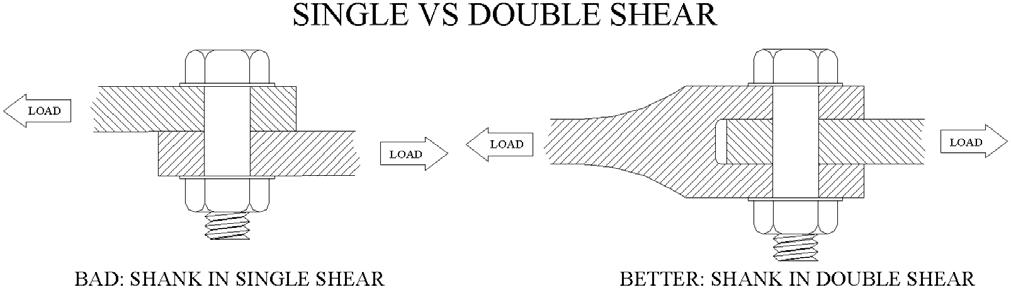
10.1Prefer Double-Shear Joints
| Shear Type | Description | Load Capacity | Application Example |
| Single Shear | One shear plane (e.g., bolt through 2 plates) | Lower | Light-duty brackets |
| Double Shear | Two shear planes (e.g., bolt through 3 plates) | 2× higher | High-shear applications (motor mounts, transmission assemblies) |
Automation Workflow:
- CNC batch-drills double-shear holes.
- Press-in machines install fasteners in the middle plate.
- Insertion machines tighten bolts for final assembly.
- Industry Example: Wind turbine blade joints use double-shear designs, with thread rolling machines ensuring high-precision threads for uniform stress distribution.
10.2Edge Distance Requirements
Rule: Distance from bolt hole center to workpiece edge ≥ 1× major thread diameter (ISO 14587).
Example: M10 bolt → ≥10 mm edge distance.
Consequences of Poor Sizing:
| Edge Distance | Issue |
| Too Small | Insufficient material → edge tearing (worse in aluminum). |
| Too Large | Unnecessary part weight/size (conflicts with lightweight design, e.g., automotive bodies). |
Design Note for Sheet Metal:Add ≥3 mm clearance for press-in machine heads (avoids edge interference during installation). Align edge distance consistency with thread rolling machine-produced fastener lengths (prevents excessive protrusion or insufficient engagement).
11.0Conclusion
In global manufacturing, fasteners are the critical link between components and system reliability. Their design and application must adhere to ISO standards and prioritize automation compatibility—from thread rolling machine processes to insertion/press-in machine integration. Every step, from thread selection to joint design, relies on engineering principles and proven industrial practices to minimize failure risks and enhance global market competitiveness.