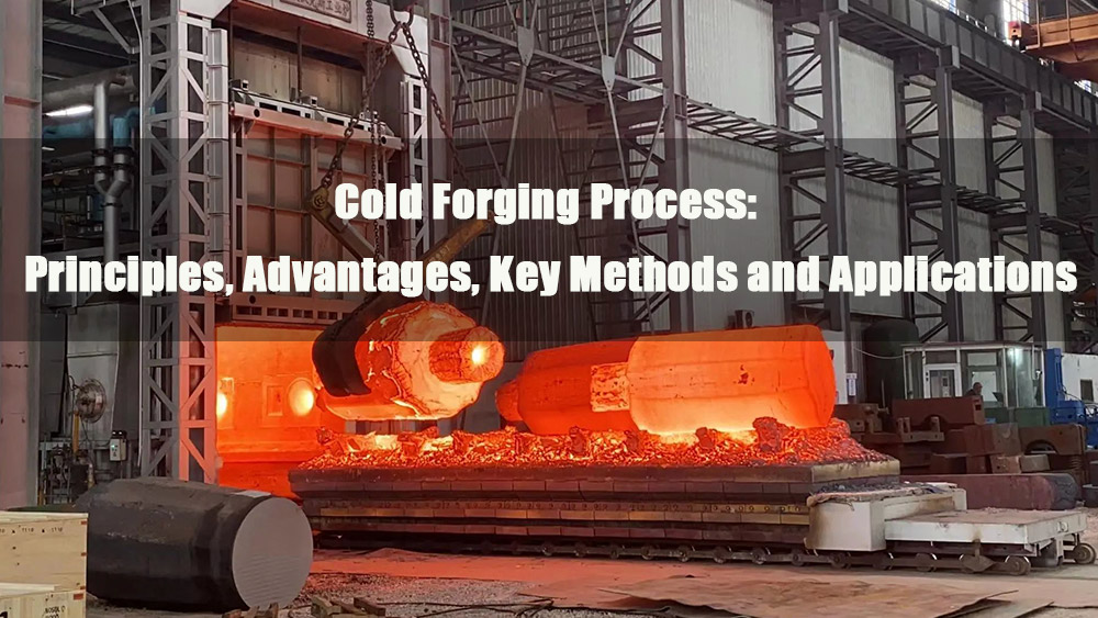
- 1.0Definition and Core Forming Mechanism of Cross-Wedge Rolling
- 2.0Classification and Technical Characteristics of Cross-Wedge Rolling Processes
- 3.0Core Technical Bottlenecks in Cross-Wedge Rolling: Die Design and Optimization
- 4.0Application of Finite Element Analysis (FEA) in Cross-Wedge Rolling Processes
- 5.0Industrial Applications and Technical Advantages of Cross-Wedge Rolling
- 6.0Future Development Trends and Research Directions
- 7.0Frequently Asked Questions (FAQ)
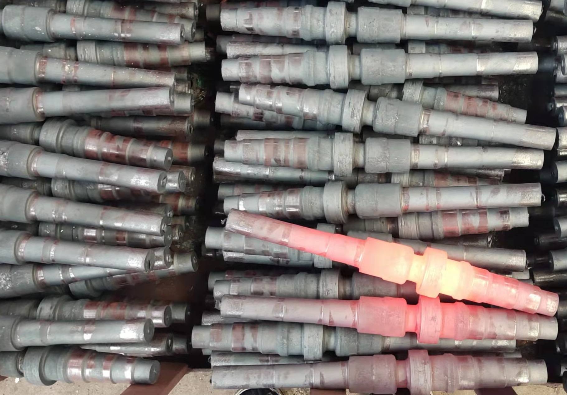
In the manufacturing processes of rotationally symmetric components such as automotive drivetrain shafts, textile machinery spindles, and stepped shafts in general machinery, cross-wedge rolling technology has emerged as an efficient plastic forming method. With its unique capability of controlling material deformation, it enables the precise transformation of cylindrical billets into axially varying diameter workpieces. By significantly enhancing production efficiency and material utilization, this technology has become one of the indispensable core processing methods in modern manufacturing.
1.0Definition and Core Forming Mechanism of Cross-Wedge Rolling
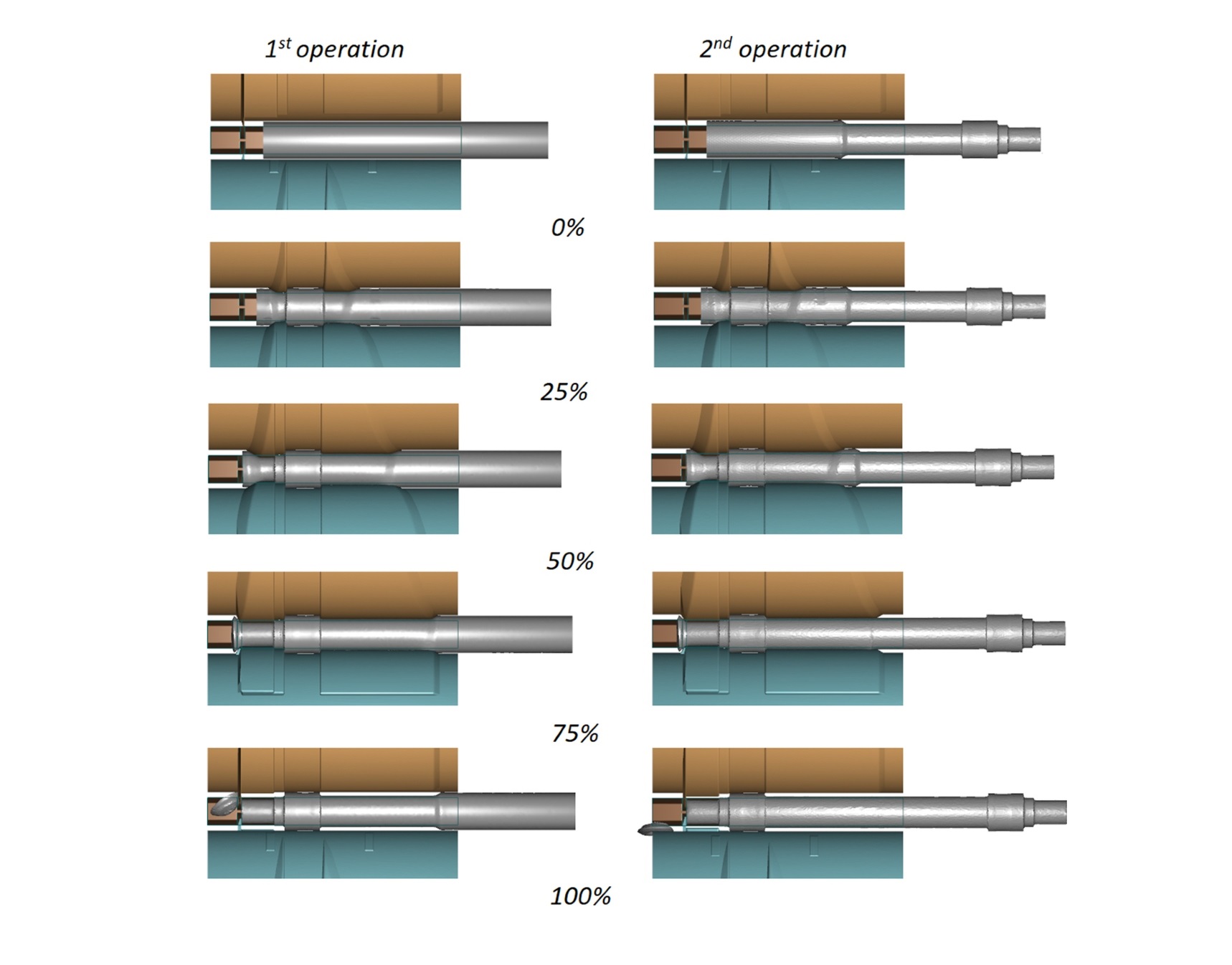
Cross-wedge rolling (CWR) is a rotary forming process based on the principles of metal plastic deformation. Its fundamental mechanism involves the controlled movement of wedge-shaped tools, which apply radial compressive forces and axial tensile stresses to a cylindrical billet. Through continuous plastic deformation, the billet is precisely transformed into a rotationally symmetric workpiece with predetermined axial diameter variations.
This process is typically performed on a Cross Wedge Rolling Machine, which applies precise radial and axial forces to achieve efficient forming.
Compared with conventional profile rolling, Cross-Wedge Rolling demonstrates an essential distinction:
- Traditional rolling primarily reduces the overall cross-sectional thickness of the workpiece and is mainly applied to plates and profiles.
- Cross-Wedge Rolling, by contrast, leverages the geometry of wedge-shaped tools to induce non-uniform volumetric flow along the billet’s axis. The coordinated effects of localized compression and axial elongation enable the efficient formation of complex rotational features such as steps and tapers.
Application Modes:
- Preforming: Used prior to forging, machining, or other subsequent operations, providing near-net-shape billets that reduce machining allowance and energy consumption.
- Direct forming: For relatively simple medium- and small-sized shafts (e.g., auxiliary shafts in automotive transmissions), final parts can be produced in a single rolling step, achieving “high efficiency with fewer operations.”
Technical Advantages:
- High production efficiency: Under continuous rolling, a single shift can produce thousands of parts, with efficiency 5–20 times higher than traditional machining processes.
- Extended die service life: Tools made from high-strength, wear-resistant materials can process tens of thousands of parts per service cycle, significantly lowering unit costs.
- High material utilization: With forming losses below 10%, material utilization reaches 80%–90%, representing an improvement of approximately 30%–40% compared with machining processes (40%–60%).
2.0Classification and Technical Characteristics of Cross-Wedge Rolling Processes
Depending on the geometry and motion pattern of wedge-shaped tools, Cross-Wedge Rolling can be divided into three mainstream process types. Each method is tailored to specific workpiece features and accuracy requirements:
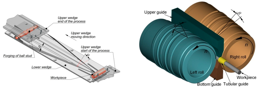
- Convex-surface tools with synchronous rotation: Employing dual or multiple convex wedge-shaped rollers rotating in the same direction at equal speed, the billet rotates in the opposite direction due to friction while radial compression induces reduction and axial elongation.
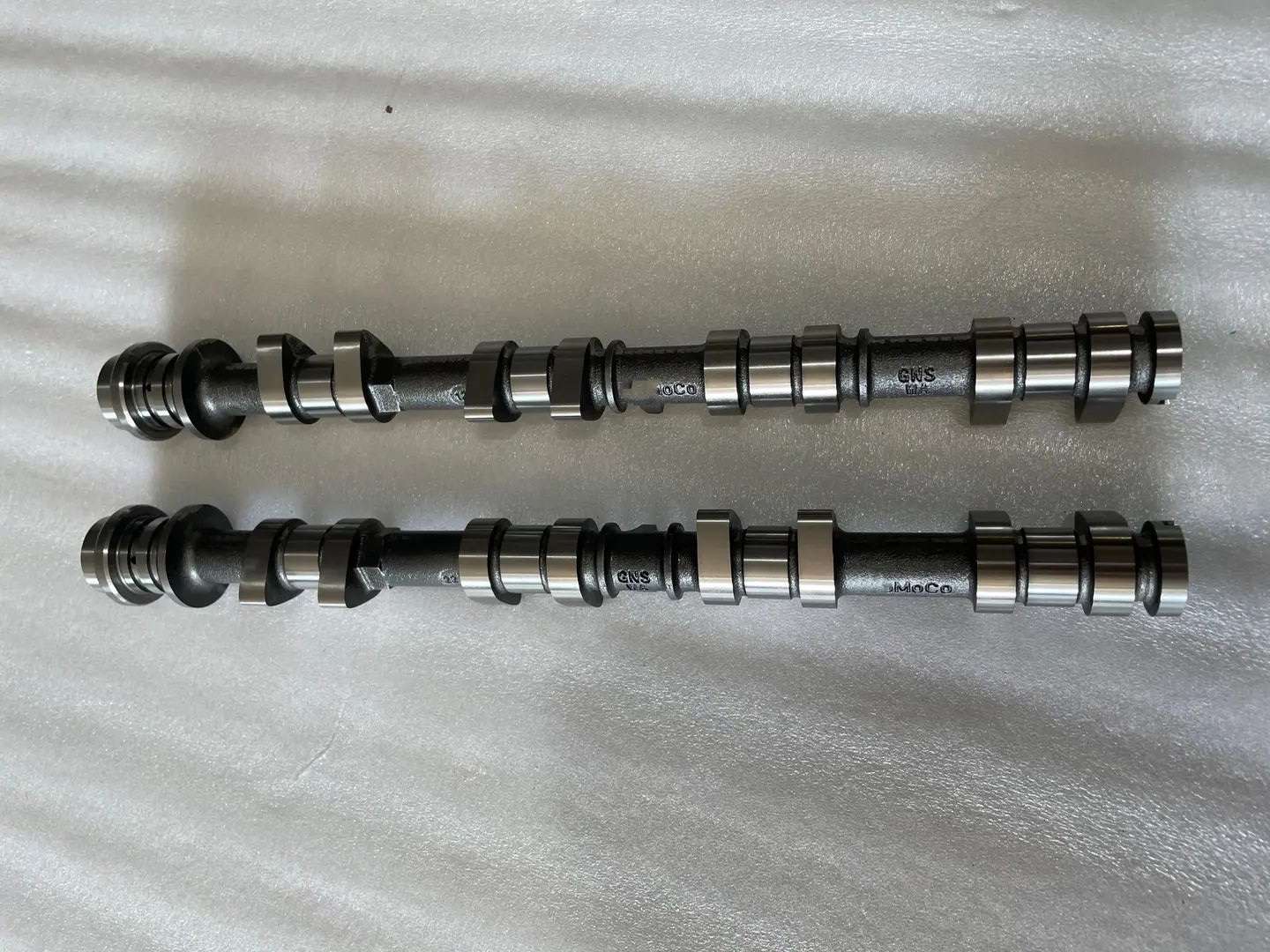
- Characteristics: Uniform load distribution and stable deformation. Suitable for shafts with diameters of 6–150 mm and lengths of 40–1200 mm. High forming accuracy (dimensional tolerance ±0.1 mm, surface roughness Ra1.6–3.2 μm). Commonly applied in preforming of critical components such as automotive transmission shafts and engine camshafts.
- Fixed concave – rotating convex tool combination:
A hybrid configuration where a fixed concave cavity constrains billet geometry, while the rotating convex wedge tool provides driving force and radial pressure. The billet deforms progressively within the cavity constraints.- Characteristics: High local forming accuracy, capable of producing asymmetric tapers and special grooves. Applied to aerospace special shafts and non-standard stepped shafts in construction machinery.
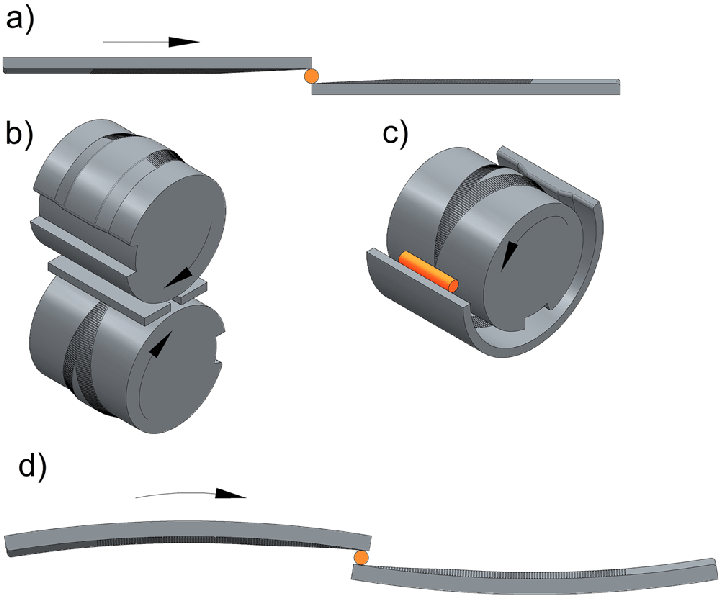
- Opposing flat wedges with linear motion:
Two flat wedge-shaped tools move linearly in opposite directions, compressing the billet radially to achieve reduction and axial elongation.- Characteristics: Simple die structure, low manufacturing and maintenance costs, flexible parameter adjustment. Suitable for medium- and small-batch production of slender shafts such as textile spindles and printing press transmission shafts, effectively reducing process development and equipment investment costs.
Classification and Technical Characteristics of Cross-Wedge Rolling
| Process Type | Tool Design | Tool Motion | Billet Deformation Mode | Applicable Dimensions | Accuracy & Surface Quality | Typical Applications |
| Convex-surface synchronous roll | Dual/multi convex-surface rolls | Synchronous rotation | Radial reduction + axial elongation | Ø6–150 mm, L40–1200 mm | Tolerance ±0.1 mm, Ra1.6–3.2 μm | Transmission main shafts, camshafts |
| Fixed concave + rotating convex | Fixed cavity + rotating wedge | Combined static/rotary | Local complex contour forming | Non-standard asymmetric shafts | High local accuracy | Aerospace shafts, construction machinery parts |
| Opposing flat wedges (linear) | Flat wedge tools | Opposite linear motion | Radial reduction + axial elongation | Slender medium-small shafts | Medium-to-high precision | Textile spindles, printing press shafts |
3.0Core Technical Bottlenecks in Cross-Wedge Rolling: Die Design and Optimization
Despite the high efficiency and material utilization advantages of cross-wedge rolling (CWR), die design and optimization remain the principal challenges limiting its wider application. The difficulties are mainly concentrated in three aspects:
- Complex parameter design: The die must be precisely designed according to the workpiece’s diameter variation profile, involving key parameters such as wedge angle, entry zone length, spreading zone slope, and sizing zone dimensions. These parameters directly affect billet deformation rate, stress–strain distribution, and forming quality. As they are strongly coupled, obtaining a feasible solution often requires multiphysics coupled analysis, demanding high theoretical knowledge and practical experience from designers.
- Stringent machining accuracy requirements: The working surfaces of the die must achieve contour accuracy within ±0.05 mm and surface roughness below Ra 0.8 μm to ensure dimensional precision and surface quality of the workpiece. Such requirements necessitate advanced equipment such as five-axis machining centers and wire-cut EDM, leading to long production cycles and high manufacturing costs.
- Time- and resource-consuming trial-and-error process: Traditional die development relies on repeated “design–machining–trial–adjustment” iterations. This process not only generates large quantities of defective billets but also occupies rolling mill resources. Typically, the development cycle spans 2–3 months, substantially increasing process development cost and time.
4.0Application of Finite Element Analysis (FEA) in Cross-Wedge Rolling Processes
Finite element simulation has become a key tool in addressing the challenges of die design and improving process stability in Cross-Wedge Rolling. Its contributions are primarily reflected in four areas:
- Virtual optimization of die parameters:
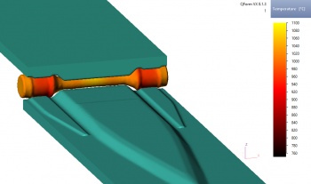
By establishing thermo-mechanical coupled finite element models, billet deformation can be simulated under varying wedge angles, feed rates, and rolling temperatures. The resulting stress, strain, and temperature distributions enable rapid identification of conditions that lead to defects such as cracks or laps. This allows parameter optimization in a virtual environment, significantly reducing the need for physical trials and lowering development costs. - Integrated simulation of the entire process chain:
FEA enables unified modeling of the “Cross-Wedge Rolling preforming–subsequent forging” process. Temperature fields, strain histories, and microstructural states of the preformed billet can be transferred as initial conditions for downstream forging simulations, thereby improving predictive accuracy and providing reliable input for forging parameter optimization. - Prediction and control of forming defects:
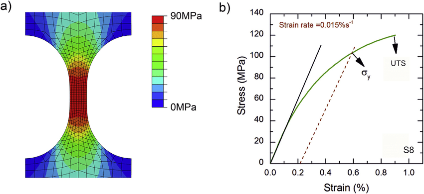
Simulation can predict potential internal cracks, surface laps, and dimensional deviations in advance, while also revealing their formation mechanisms. Based on these insights, die parameters or process conditions (e.g., rolling temperature, feed rate) can be adjusted to effectively reduce defect risks and ensure forming quality. - Knowledge accumulation and transfer:
Visualization outputs such as stress–strain contour maps and deformation trajectories provide engineers with intuitive insights into process mechanisms and parameter effects, thereby shortening learning cycles. Moreover, simulation data can be structured into standardized parameter databases, supporting systematic knowledge transfer and reducing reliance on experience-based expertise.
Die Parameters and the Role of Simulation in Optimization
| Die Parameter | Function | Design Difficulty | Role of Simulation in Optimization |
| Wedge angle | Controls billet deformation rate | Strong parameter coupling, highly experience-dependent | Virtual optimization avoids excessive or insufficient angles |
| Entry zone length | Determines initial material penetration | High precision requirements | FEA adjustment reduces trial-and-error cycles |
| Spreading slope | Governs radial extension velocity | Significant effect on billet reduction | Stress distribution analysis guides optimal design |
| Sizing zone size | Controls final dimensions & surface finish | Requires micron-level machining accuracy | Simulation enables prediction of dimensional precision |
5.0Industrial Applications and Technical Advantages of Cross-Wedge Rolling
Due to its high efficiency, material savings, and suitability for mass production, cross-wedge rolling (CWR) has been widely applied in industries such as automotive, machinery, and energy. Typical application scenarios include:
- Automotive manufacturing:
Extensively used in the performing or final shaping of key components such as engine crankshafts, transmission shafts, and drive half-shafts. Compared with traditional machining, material utilization improves by 30%–40%, significantly reducing unit costs. - Machinery and equipment:
Applicable to the production of medium- and small-sized shafts such as machine tool spindles, printing press drive shafts, and textile machinery spindles. With high precision and reduced machining allowance, Cross-Wedge Rolling shortens subsequent machining steps and enhances assembly accuracy and overall equipment stability. - Energy equipment:
Used in the forming of large tapered shafts, connecting shafts, and transition shaft sections in wind power, nuclear power, and petroleum equipment. The process ensures sufficient strength while reducing material consumption and manufacturing costs.
Modern Cross Wedge Rolling Machine are widely used in automotive manufacturing for preforming crankshafts, transmission shafts, and drive axles.
Summary of Technical Advantages:
- High efficiency: A single shift can produce thousands of parts, with efficiency 5–20 times higher than machining.
- Low cost: Long die service life and reduced machining allowance lower overall production costs by 20%–50%.
- Superior quality: Workpieces exhibit continuous fiber flow and dense internal structures, with fatigue resistance and impact performance significantly superior to machined parts.
6.0Future Development Trends and Research Directions
With the advancement of intelligent manufacturing and digital technologies, the research and application of Cross-Wedge Rolling are evolving toward the following trends:
- Intelligent die design:
AI- and machine learning–based parameter optimization methods are emerging, enabling automatic identification of optimal wedge angles, feed rates, and rolling temperatures from large-scale finite element data. This development shortens the design cycles and realizes “trial-free” design. - Multiphysics coupled simulation:
Future simulations will go beyond thermo-mechanical coupling, incorporating microstructural evolution, recrystallization, and residual stress analysis. This will enable more accurate predictions of the mechanical properties and service life of rolled parts. - Advanced material applications: To meet the forming requirements of difficult-to-deform materials such as high-strength steels, titanium alloys, and nickel-based alloys, research will focus on new high-wear-resistant die materials and surface strengthening technologies to extend tool life and reliability.
- Green manufacturing and carbon reduction:
By lowering heating temperatures, optimizing rolling paths, and improving material utilization, Cross-Wedge Rolling is expected to further reduce energy consumption and carbon emissions, aligning with the goals of sustainable manufacturing. - Digital integration of process chains:
Future Cross-Wedge Rolling production lines will be digitally integrated with forging, heat treatment, and in-line inspection, establishing a closed-loop “design–manufacturing–inspection–feedback” system. This will drive the comprehensive upgrade of Cross-Wedge Rolling toward intelligent manufacturing.
7.0Frequently Asked Questions (FAQ)
What is the cross-wedge rolling (CWR) process?
Cross-Wedge Rolling is a forming technology for rotationally symmetric workpieces, based on the principles of metal plastic deformation. By applying controlled radial pressure and axial tensile forces through wedge-shaped tools, the process enables the shaping of shafts with complex geometries such as steps and tapers.
How does Cross-Wedge Rolling differ from conventional machining or free forging?
Cross-Wedge Rolling forms parts through continuous plastic deformation, offering high material utilization, high production efficiency, and stable dimensional accuracy. In contrast, machining and free forging generate large machining allowances, significant material waste, limited accuracy, and low efficiency.
What types of shafts are suitable for Cross-Wedge Rolling?
Cross-Wedge Rolling is applicable to automotive transmission shafts, engine camshafts, textile machinery spindles, printing press drive shafts, and non-standard stepped shafts in construction machinery. It can be used for both performing and direct part production.
What are the advantages of Cross-Wedge Rolling?
- High production efficiency: A single shift can yield thousands of parts, with efficiency 5–20 times greater than machining.
- High material utilization: 80%–90%, about 30%–40% higher than traditional processes.
- High-dimensional accuracy and surface quality: Tolerances can be controlled within ±0.1 mm, with surface roughness Ra 1.6–3.2 μm.
- Extended die service life: A single die set can process tens of thousands of parts, reducing production costs.
What are the key challenges in Cross-Wedge Rolling die design?
The design requires precise control of parameters such as wedge angle, entry zone length, spreading zone slope, and sizing zone dimensions. These parameters are strongly coupled and directly influence billet deformation and forming quality, making the design, machining, and trial process highly complex.
References
pmc.ncbi.nlm.nih.gov/articles/PMC6766045/
www.qform3d.com/processes/rolling/crosswedge
www.amtengine.com/en/oborudovanie/advantages-cross-wedge-rolling-technology/
www.mdpi.com/1996-1944/12/14/2287