- 1.0¿Qué son las operaciones de conformado de metales?
- 2.0¿Qué es la esquila?
- 3.0¿Qué es mordisquear?
- 4.0¿Qué es la flexión?
- 5.0¿Qué es el dibujo?
- 6.0¿Qué es el relieve?
- 7.0¿Qué se está formando?
- 8.0¿Qué es el coining (squeezing)?
- 9.0Comprensión de la mecánica de flexión y métodos comunes
- 10.0Factores importantes en la flexión: tolerancia de flexión, recuperación elástica y fuerza
- 11.0Operaciones de dibujo: Producción de formas huecas a partir de chapa metálica plana
- 12.0Conclusión
- 13.0Preguntas frecuentes
La fabricación de chapa metálica es fundamental en la fabricación moderna, ampliamente utilizada en las industrias automotriz, aeroespacial, de la construcción y de electrodomésticos. Comprender los procesos principales, como el corte, el roído, el doblado, el embutido, el estampado y el acuñado, es esencial para ingenieros y fabricantes que buscan optimizar la eficiencia de la producción y la calidad del producto.
1.0¿Qué son las operaciones de conformado de metales?
Las operaciones de conformado de metales implican moldear el material sin eliminarlo, lo que significa que no se desperdicia material. La chapa metálica se somete a tensiones superiores a su límite elástico, pero se mantiene por debajo de su resistencia última, lo que garantiza que adquiera una nueva forma permanente.
Las operaciones más comunes de conformado de metales incluyen:
- Doblado
- Dibujo
- Realce
- Formando
- Acuñación (también conocida como exprimido)
2.0¿Qué es la esquila?
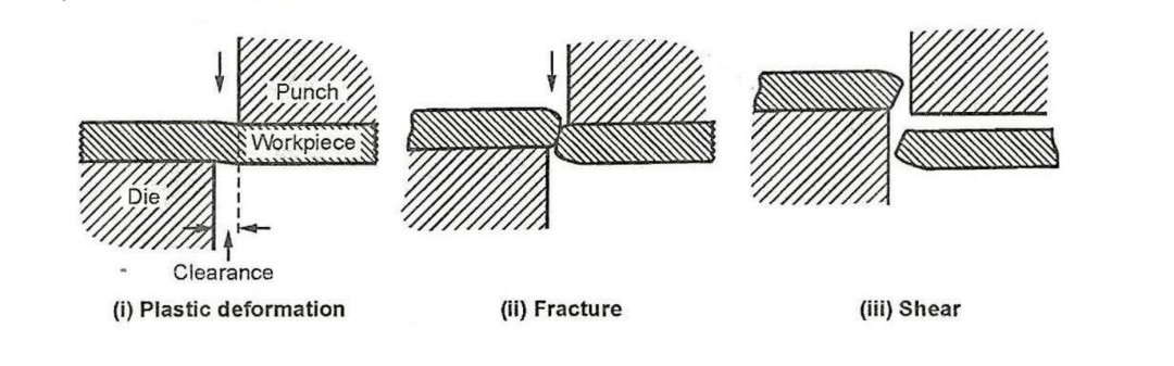
El cizallamiento es un proceso que se utiliza para cortar líneas rectas sobre láminas, tiras o barras de metal. Consta de tres etapas principales:
- Deformación plástica
- Fractura (propagación de grietas)
- Cizallamiento (separación de materiales)
Cuando se coloca una pieza metálica entre las cuchillas superior e inferior de una cizalla y se aplica presión, el material experimenta primero una deformación plástica. A medida que aumenta la presión, comienzan a formarse grietas en los filos de las cuchillas. Estas grietas se propagan y se unen, provocando el cizallamiento del material.
Máquinas de corte—desde modelos manuales hasta hidráulicos y mecánicos— se utilizan para realizar este proceso de manera eficiente y precisa, especialmente en aplicaciones industriales o de gran volumen.
3.0¿Qué es mordisquear?
El mordisqueo se utiliza generalmente como sustituto del troquelado. Está diseñado para cortar piezas planas de chapa metálica y es adecuado para formas que van desde contornos simples hasta complejos. Este proceso se utiliza principalmente para producir pequeñas cantidades de componentes.
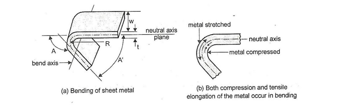
4.0¿Qué es la flexión?
El doblado es un proceso en el que una lámina metálica recta se transforma en una forma curva. Durante el doblado, el material se somete a esfuerzos de tracción y compresión, lo que resulta en una deformación plástica que supera el límite elástico, pero por debajo de la resistencia última.
Los tipos más comunes de flexión incluyen:
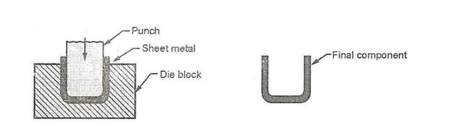
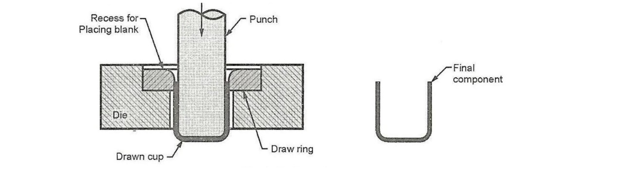
- Doblado en U
El doblado en U (también llamado doblado de canal) utiliza una cavidad de matriz con forma de "U", lo que da como resultado un componente con un perfil en forma de U. Esta operación se realiza comúnmente utilizando un prensa plegadora máquina equipado con matrices en forma de U. - Doblado en V
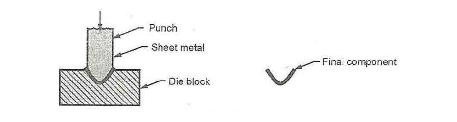
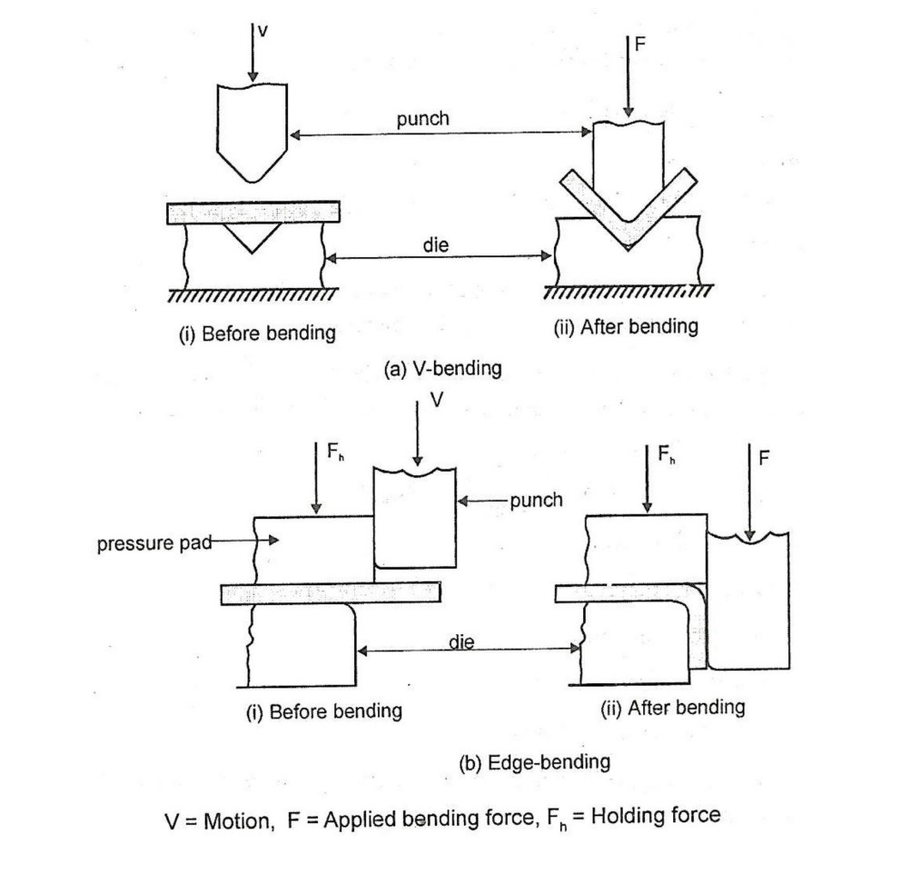
El plegado en V utiliza un punzón en forma de cuña y una matriz en V. El ángulo de la V puede variar de agudo a obtuso, incluso 90°. Es una de las técnicas de plegado más utilizadas en las operaciones de prensa plegadora gracias a su versatilidad y precisión. - Doblado de ángulos
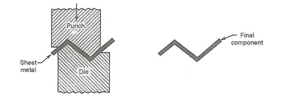
El doblado angular es un término general para doblar chapa metálica en un ángulo agudo. También puede realizarse utilizando un prensa plegadora, dependiendo de la geometría y el ángulo requerido. - Curling
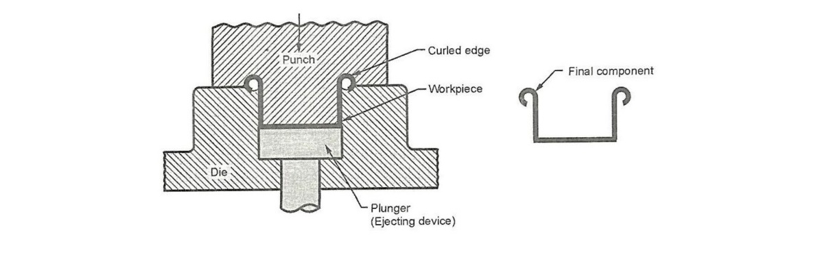
El rizado consiste en curvar el borde de la chapa metálica alrededor de una forma. Tanto el punzón como la matriz contienen cavidades parciales para dar forma al material. Tras la operación, el punzón se retrae y la pieza se expulsa mediante un émbolo. Este método se utiliza para fabricar tambores, sartenes, ollas y artículos similares. - Doblado de rodillos
El doblado por rodillos utiliza un conjunto de rodillos para doblar gradualmente piezas grandes de chapa metálica en secciones curvas. Se utiliza comúnmente para fabricar grandes tanques de almacenamiento, recipientes a presión, tuberías y componentes estructurales. - Doblado en máquina de 4 carros
Este método se utiliza para piezas relativamente cortas. Estas máquinas varían en diseño y utilizan movimientos de matriz tanto verticales como laterales para formar formas complejas. - Doblado de bordes
El doblado de bordes implica una carga en voladizo, donde una almohadilla de presión sostiene la pieza de trabajo contra la matriz mientras un punzón fuerza el metal a doblarse sobre el borde. Prensa frenos Las máquinas equipadas con matrices de limpieza también pueden realizar este tipo de doblado. El doblado de cantos suele limitarse a ángulos de 90° o menos, aunque las matrices de limpieza pueden diseñarse para ángulos mayores.

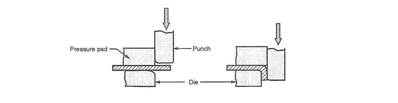
Debido a la complejidad de las almohadillas de presión y las matrices de limpieza, este método es más costoso pero adecuado para producciones de gran volumen.
5.0¿Qué es el dibujo?
El embutido es un proceso en el que un punzón introduce una pieza plana de chapa metálica en la cavidad de una matriz, lo que provoca que el material fluya plásticamente y adquiera una forma similar a una copa. Se utiliza para crear piezas huecas a partir de chapas planas.
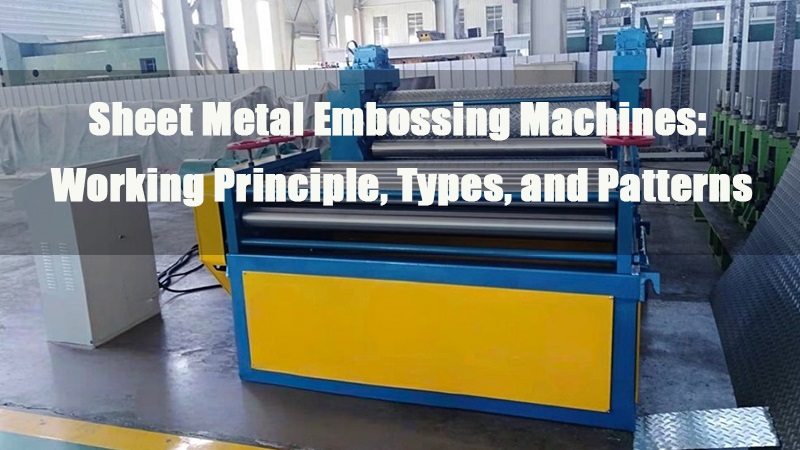
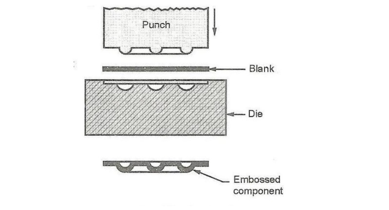
6.0¿Qué es el relieve?
El gofrado se utiliza para crear diseños en relieve o en huecos sobre chapa metálica con fines decorativos o funcionales. Puede utilizarse para imprimir logotipos, marcas registradas, números de pieza u otras marcas de identificación.
7.0¿Qué se está formando?
Durante el conformado, el metal se somete a una tensión superior a su límite elástico para que conserve permanentemente una nueva forma, reproduciendo directamente el contorno del punzón y la matriz. A diferencia del embutido, no hay flujo de metal significativo. Este proceso se utiliza para la fabricación de artículos como paneles de puertas, muebles de acero y carrocerías de aeronaves.
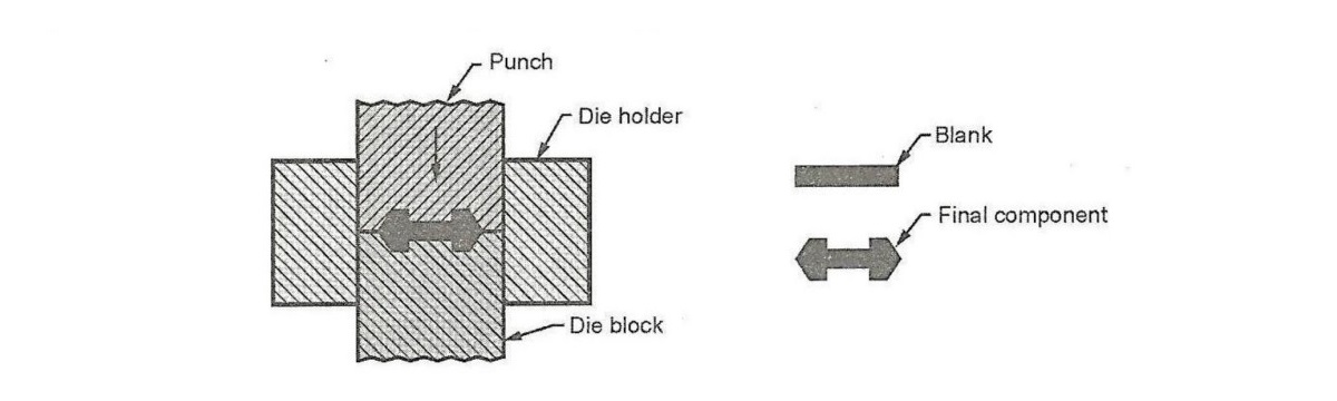
8.0¿Qué es el coining (squeezing)?
El acuñado es un proceso de conformado de precisión en el que se coloca una pieza metálica entre un punzón y una matriz, y se aplica alta presión. El metal fluye plásticamente en frío, llenando completamente la cavidad de la matriz. Este proceso se utiliza para producir monedas, medallas y componentes ornamentales con finos detalles superficiales.
9.0Comprensión de la mecánica de flexión y métodos comunes
En el doblado de chapa metálica, el metal se deforma alrededor de un eje recto. El material en el interior de la curva se comprime, mientras que el material en el exterior se estira. El metal se deforma plásticamente para que la curva conserve su forma después de eliminar la tensión. El doblado generalmente no modifica significativamente el espesor del material.
Dos métodos de doblado comunes son:
- Doblado en VEste método, que se realiza con un punzón y una matriz en forma de V, permite una variedad de ángulos de plegado, desde agudos hasta obtusos. Se utiliza generalmente para aplicaciones de baja producción y suele realizarse en una prensa plegadora. Las matrices en V son relativamente sencillas y económicas.
- Doblado de bordesEste método utiliza una almohadilla de presión para sujetar la base de la pieza mientras un punzón dobla la chapa sobre el borde de la matriz. El doblado de bordes se limita a ángulos de 90° o menos, a menos que se utilicen matrices de limpieza más complejas. Estas matrices son más costosas que las matrices en V, pero son adecuadas para la producción a gran escala.
10.0Factores importantes en la flexión: tolerancia de flexión, recuperación elástica y fuerza
Tolerancia de curvatura
Cuando el radio de curvatura es pequeño en relación con el espesor del material, el material tiende a estirarse durante el doblado. Calcular con precisión este estiramiento es esencial para garantizar que la pieza final cumpla con las especificaciones de diseño. La tolerancia de curvatura (TA) es la longitud estimada del eje neutro antes del doblado y tiene en cuenta el estiramiento del material. Se puede calcular mediante la fórmula general:
BA = (π / 180) × A × (R + K × t)
Dónde:
- BA = Margen de curvatura (en mm)
- A = Ángulo de curvatura (grados)
- R = Radio de curvatura interior (mm)
- t = Espesor del material (mm)
- K = Factor para estimar la ubicación del eje neutro (comúnmente entre 0,33 y 0,5, dependiendo del material y las condiciones de curvatura)

El estiramiento generalmente ocurre cuando el radio de curvatura es pequeño en comparación con el espesor de la chapa.
Recuperación elástica
Tras liberar la presión de flexión, la energía elástica almacenada en el material provoca una recuperación parcial a su forma original, lo que se denomina recuperación elástica. Se define como el aumento del ángulo incluido de la pieza doblada en comparación con el ángulo de la herramienta tras la descarga.
SB = θ₁ – θ₂
Dónde:
- SB = Retorno elástico (grados)
- θ₁ = Ángulo incluido de la pieza de chapa metálica después del doblado
- θ₂ = Ángulo incluido de la herramienta de conformado
Fuerza de flexión
La fuerza necesaria para el doblado depende de factores como la geometría del punzón y la matriz, la resistencia del material, el espesor de la chapa y el ancho de la pieza. La fuerza máxima de doblado se puede estimar con:
F = (Kbf × TS × ω × t²) / D
Dónde:
- F = Fuerza de flexión (N)
- TS = Resistencia a la tracción del material (MPa)
- ω = Ancho de la pieza (mm)
- t = Espesor de la chapa (mm)
- D = Dimensión de la abertura de la matriz (mm)
- Kbf = Coeficiente de fuerza de flexión
- 33 para doblado en V
- 33 para doblar bordes
11.0Operaciones de dibujo: Producción de formas huecas a partir de chapa metálica plana
El embutido es un proceso de conformado de chapa metálica que se utiliza para crear piezas con forma de copa, caja u otras piezas huecas. Se coloca una pieza plana de chapa metálica sobre la cavidad de una matriz y se introduce en ella con un punzón. Un portapiezas mantiene el material en su lugar durante la operación.
Las aplicaciones típicas incluyen:
- latas de bebidas
- Proyectiles de munición
- Fregaderos y utensilios de cocina
- Paneles de automóviles
Mecánica y etapas de la embutición profunda
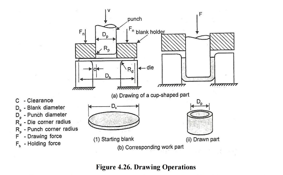
En el proceso básico de dibujo de copa:
Se dibuja una pieza en bruto de diámetro Db utilizando un punzón de diámetro Dp.
El punzón y la matriz tienen radios de esquina (Rp y Rd) para evitar desgarros.
Se proporciona una holgura C entre el punzón y la matriz:
C ≈ 1,1 × t
Se aplican dos fuerzas:
Fuerza de punzonado (F) para la deformación
Fuerza del portapiezas (Fh) para controlar el flujo de metal
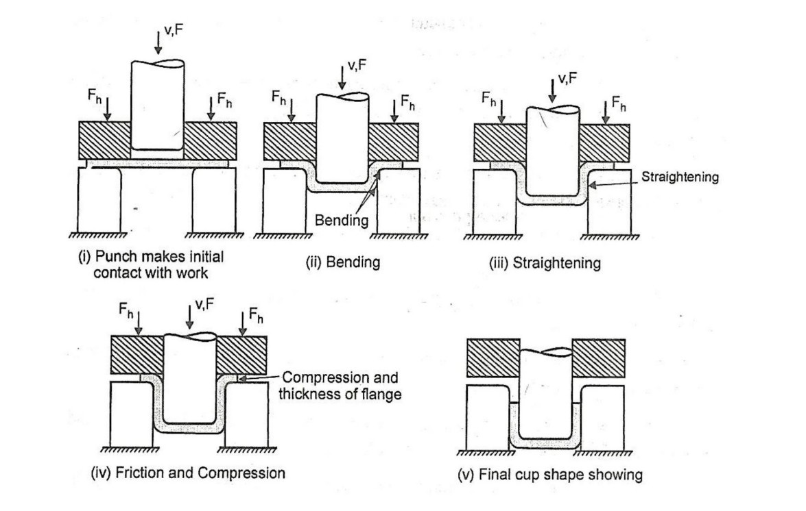
Las etapas de la embutición profunda incluyen:
Contacto inicial: el metal se dobla sobre la matriz y el radio del punzón.
Enderezamiento: las áreas previamente dobladas se enderezan a medida que se introducen en el molde.
Embutido y compresión: el material fluye desde la brida hacia la cavidad de la matriz.
La fricción (estática → dinámica) resiste el flujo.
La compresión en la brida provoca engrosamiento y posible formación de arrugas.
Dibujo continuo: el punzón continúa hacia abajo, introduciendo el metal en la matriz.
Puede producirse adelgazamiento en la pared del cilindro.
Es fundamental lograr un equilibrio entre la fuerza del portapiezas y la fricción.
Generalmente se requiere lubricación.
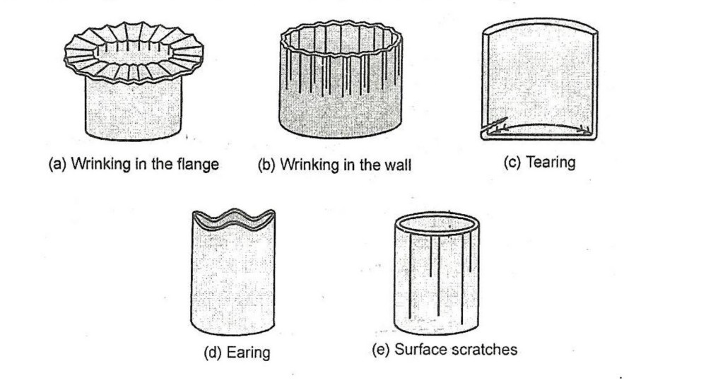
Defectos comunes en el dibujo
- Arrugas en la brida: Crestas radiales debido al pandeo por compresión.
- Arrugas en la pared: Las arrugas de la brida se introducen en la pared vertical.
- Desgarro: Grietas abiertas cerca de la base debido a la alta tensión de tracción.
- Orejas: Bordes desiguales (orejas) debido a la anisotropía de la lámina.
- Rayones superficiales: causados por superficies ásperas del molde o lubricación deficiente.
Operaciones de conformado por estiramiento: Láminas contorneadas de gran tamaño para la industria aeroespacial y automotriz
El conformado por estiramiento crea láminas grandes y contorneadas con precisión estirando el metal más allá de su límite elástico sobre un bloque de moldeo.
El springback es una cuestión clave, influenciada por:
- Tipo de material
- Espesor
- Dureza
- Radio de curvatura (un radio mayor produce una mayor recuperación elástica)
Métodos para reducir la recuperación elástica
Estiramiento excesivo mediante bloques de encofrado tipo V
Ajuste de esquinas: Acuñación de las esquinas para liberar la tensión elástica residual
Métodos de conformado por estiramiento
Método de bloques de forma
La pieza en bruto se estira sobre un único bloque de forma (matriz macho).
Método del troquel de apareamiento
Utiliza matrices macho y hembra para lograr una mayor precisión y repetibilidad.
12.0Conclusión
En resumen, los procesos de chapa metálica como el corte, el mordisqueo, el doblado, el embutido, el estampado y el acuñado desempeñan papeles vitales a la hora de dar forma a las chapas metálicas para convertirlas en componentes funcionales y precisos.
Un conocimiento profundo de la mecánica y las variables que afectan estos procesos, incluyendo la tolerancia de plegado, la recuperación elástica y el diseño de herramientas, permite a los fabricantes minimizar los defectos y optimizar la producción. Ya sea que produzca piezas planas simples o complejas,
Paneles contorneados, dominar estas técnicas es clave para una fabricación exitosa de chapa metálica.
13.0Preguntas frecuentes
P1: ¿Cuál es la principal diferencia entre doblar y embutir en la fabricación de chapa metálica?
A1: El doblado cambia la forma al deformar plásticamente el metal alrededor de un eje sin un flujo de material significativo, mientras que el estirado implica tirar del material hacia una cavidad de matriz, lo que hace que el flujo plástico forme formas huecas.
P2: ¿Cómo se puede minimizar el efecto elástico durante la flexión?
A2: La recuperación elástica se puede reducir doblando demasiado, seleccionando herramientas adecuadas, utilizando material con menos elasticidad y aplicando cálculos de tolerancia de curvatura adecuados durante el diseño.
P3: ¿Cuándo es preferible mordisquear en lugar de borrar?
A3: El mordisqueo se prefiere para cortar contornos complejos o pequeñas tiradas de producción donde el uso de matrices troqueladas sería costoso o poco práctico.
P4: ¿Qué causa las arrugas durante el dibujo profundo y cómo se pueden prevenir?
A4: Las arrugas se producen por tensiones de compresión en la zona de la brida. Se pueden minimizar optimizando la fuerza del portapiezas, la lubricación y la geometría de la herramienta.
Q5: ¿Por qué es importante la lubricación en los procesos de conformado y embutido?
A5: La lubricación reduce la fricción entre la chapa y las herramientas, lo que evita daños en la superficie, desgaste excesivo de las herramientas y defectos como desgarros o arrugas.