- 1.0¿Qué es el cizallamiento en el trabajo de metales?
- 2.0Tipos de herramientas y máquinas de corte
- 2.1Tijeras de hojalatero
- 2.2Tijeras de hojalatero
- 2.3Cizalla para cortar agujeros
- 2.4Curva de corte
- 2.5Máquina de guillotina
- 2.6Cizalla de palanca
- 2.7Cizalla circular (cizalla de rodillos)
- 2.8Tijeras eléctricas para hojalatero
- 2.9Herramientas de corte (punzón y matriz)
- 2.10Máquina cizalla accionada por motor
- 3.0Construcción y principios de funcionamiento de las tijeras
- 4.0El proceso de esquila: operación paso a paso
- 5.0Técnicas de corte: métodos de corte y su uso
- 6.0Procedimientos operativos: Realización de tareas de corte
- 7.0Pautas de seguridad para operaciones de esquila
- 8.0Preguntas frecuentes
- 9.0Conclusión
El cizallado es un proceso fundamental en la fabricación de chapa metálica, que permite cortar metales de forma rápida y sin virutas en formas específicas. Tanto si eres profesional, técnico o principiante en metalistería, comprender cómo funciona el cizallado, qué máquinas se utilizan y cómo mantener la seguridad es fundamental.
En este artículo, le explicaremos el propósito, los beneficios, las herramientas, las operaciones y los procedimientos de seguridad de la esquila.
1.0¿Qué es el cizallamiento en el trabajo de metales?
El cizallamiento es un método de corte sin viruta para chapas metálicas y perfiles de acero. Produce cortes rectos o curvos en longitudes seleccionables sin eliminar material.
Ventajas del corte sobre el aserrado o el cincelado:
- Sin pérdida de material durante el corte
- Alineación precisa a lo largo de líneas trazadas
- Se requiere un acabado mínimo en las superficies cortadas.
- Velocidad de corte más rápida
- Trayectorias de corte rectas o curvas
Las técnicas de corte más comunes incluyen:
- Corte en
- Corte
- Recorte
- Puñetazos

2.0Tipos de herramientas y máquinas de corte
Se utilizan diferentes herramientas para el corte según el grosor del material y el estilo de corte. A continuación, se presentan los tipos de cizallas más comunes:
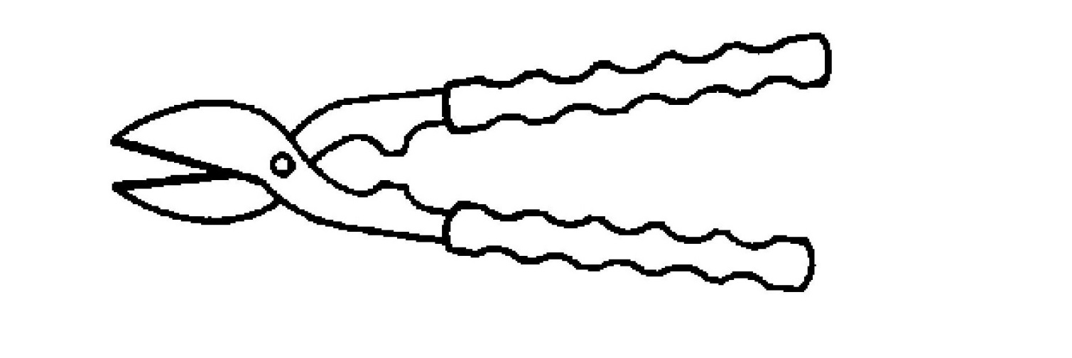
2.1Tijeras de hojalatero
Se utiliza para cortes cortos, rectos o curvos en chapas metálicas delgadas.
Espesor máximo de corte:
- Acero – 0,7 mm
- Latón – 0,8 mm
- Cobre – 1,0 mm
- Aluminio – 1,0 a 2,5 mm
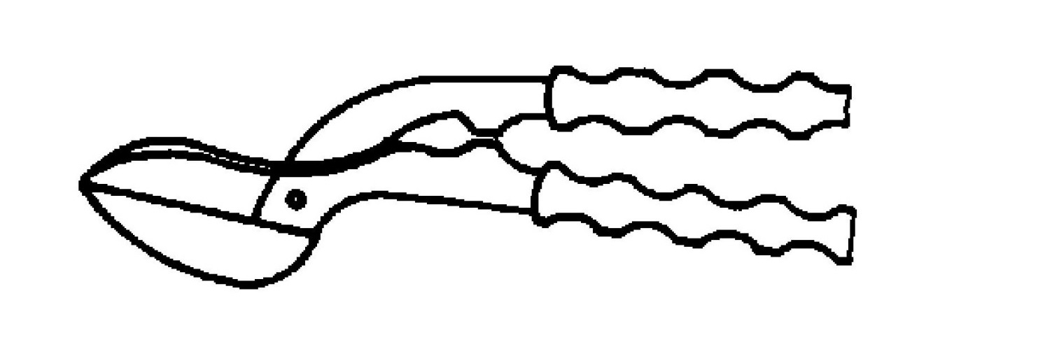
2.2Tijeras de hojalatero
Diseñado para cortes rectos más largos en láminas delgadas. El material pasa por debajo de la mano para mayor seguridad.
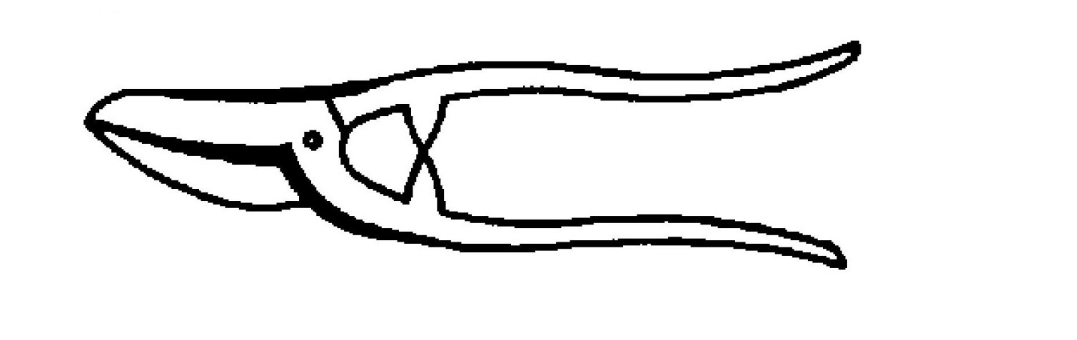
2.3Cizalla para cortar agujeros
Se utiliza para cortes curvos en metal fino. La hoja curva de un solo lado no es adecuada para cortes rectos.
2.4Curva de corte
Ideal para cortes circulares o curvos en chapas finas y de grosor medio de hasta 4 mm. La chapa puede girarse durante el corte.
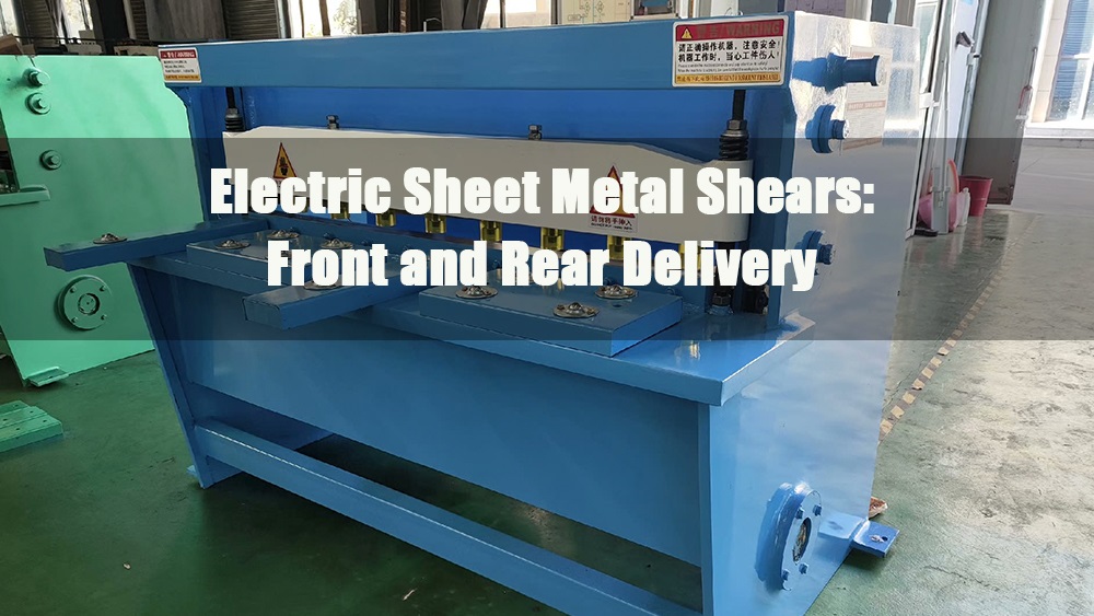
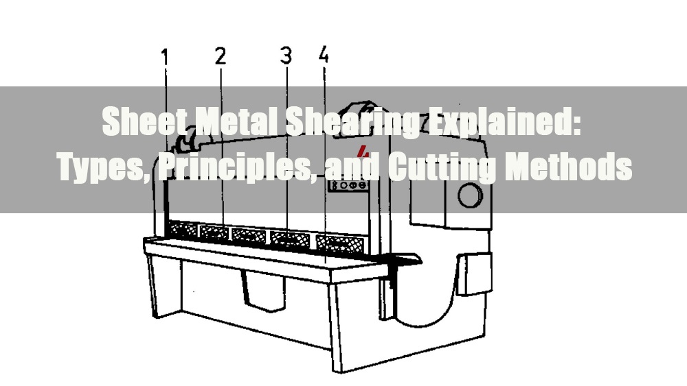
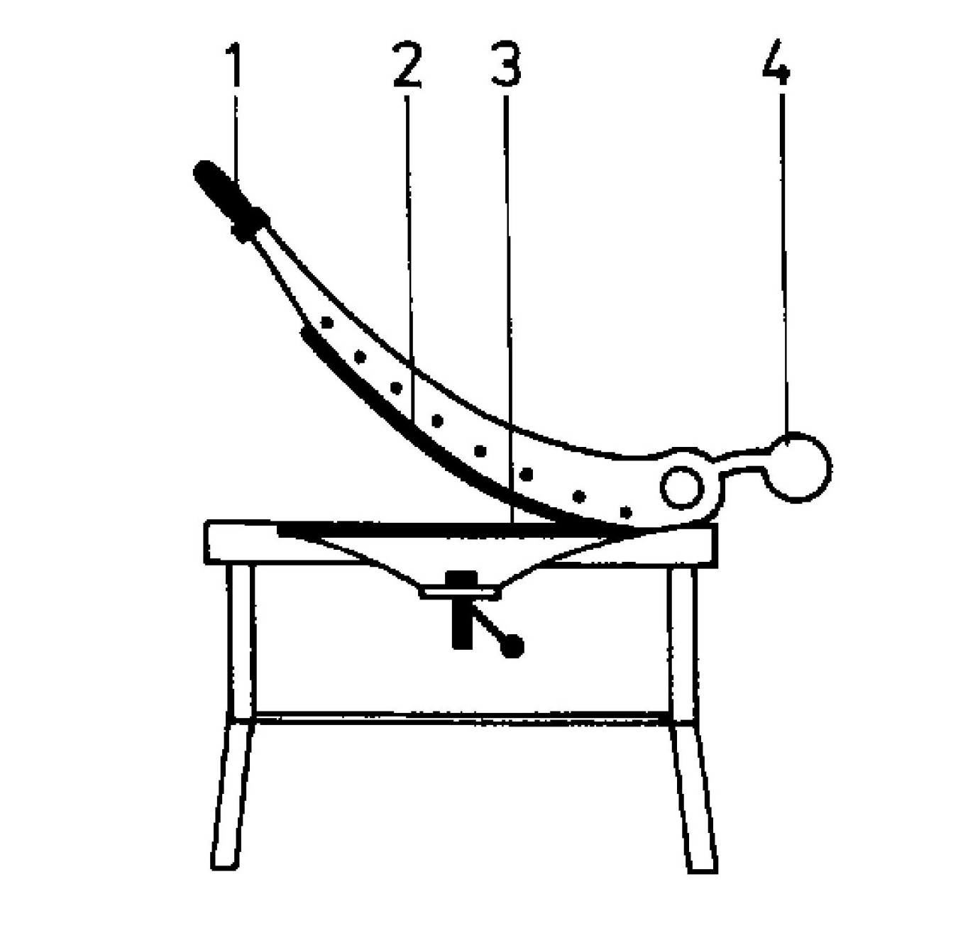
2.5Máquina de guillotina
Se utiliza para cortes rectos de láminas delgadas (~3 mm) en longitudes largas. La cuchilla superior se desliza hacia abajo contra la cuchilla inferior. Disponible en modelos manuales y eléctricos.
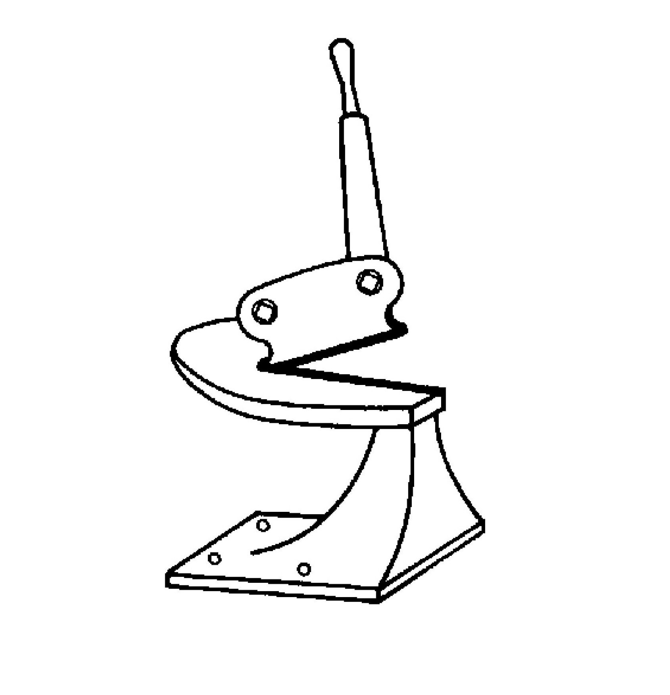
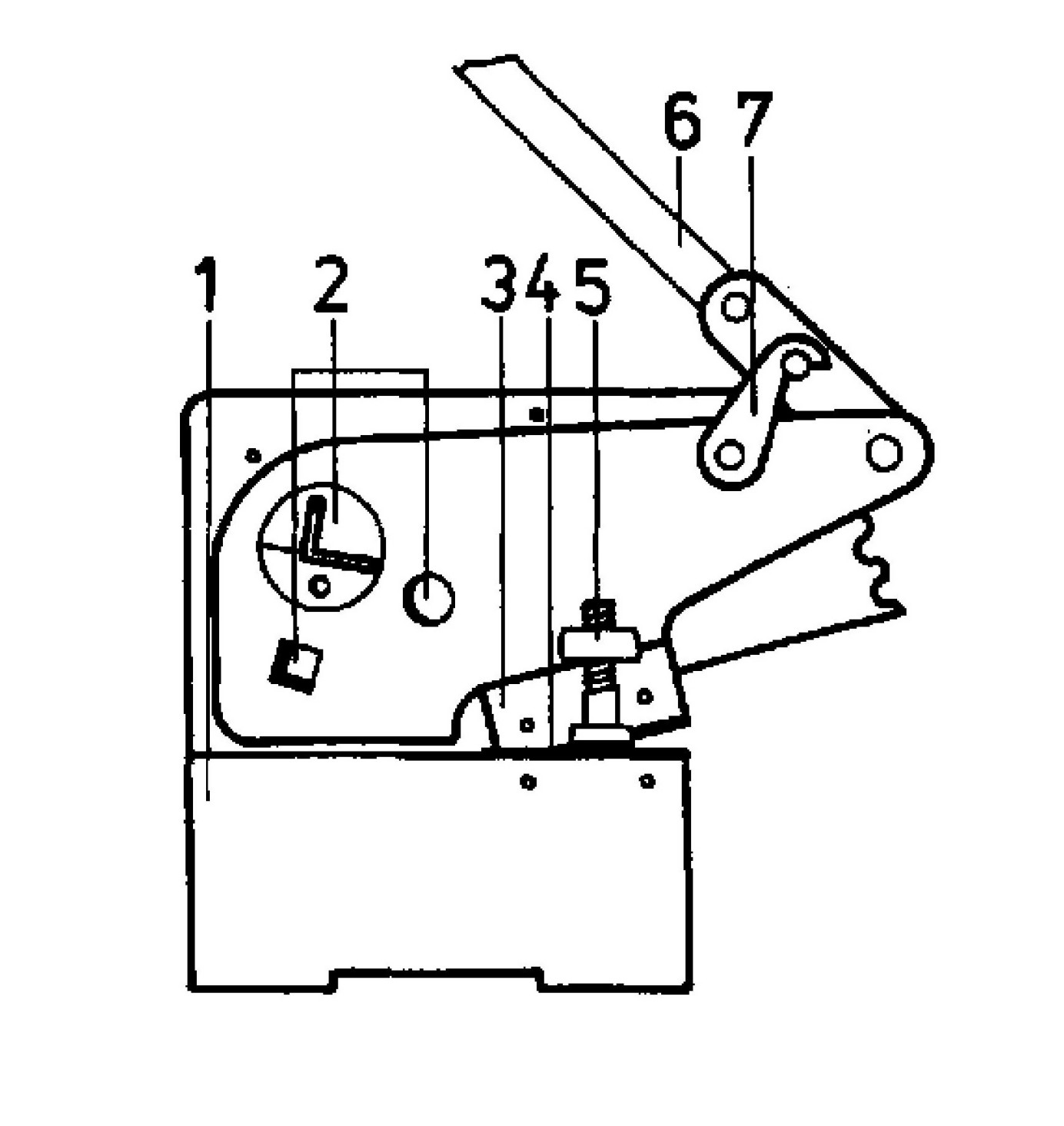
2.6Cizalla de palanca
Realiza cortes cortos, rectos o curvos, en secciones de chapa metálica o acero de espesor medio. La cuchilla superior pivota hacia abajo mediante una transmisión de palanca. Un dispositivo de bloqueo impide el movimiento involuntario de la cuchilla.
2.7Cizalla circular (cizalla de rodillos)
Se utiliza para cortes curvos largos en chapas finas o gruesas. Cuenta con cuchillas giratorias con forma de rueda. Para materiales gruesos, pueden ser necesarias varias pasadas.
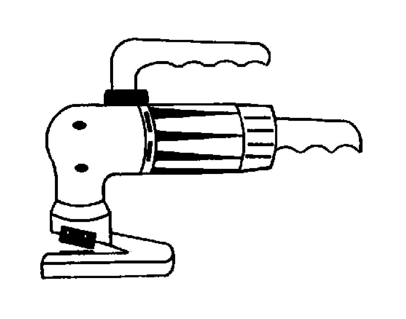
2.8Tijeras eléctricas para hojalatero
Se utiliza para cortar láminas delgadas con trayectorias curvas. La cuchilla superior se mueve rápidamente hacia arriba y hacia abajo mediante un motor, mientras el operador guía la lámina.
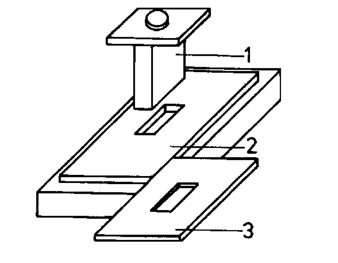
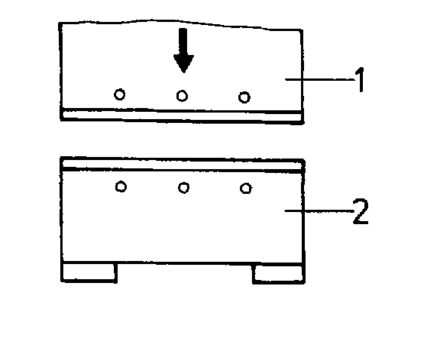
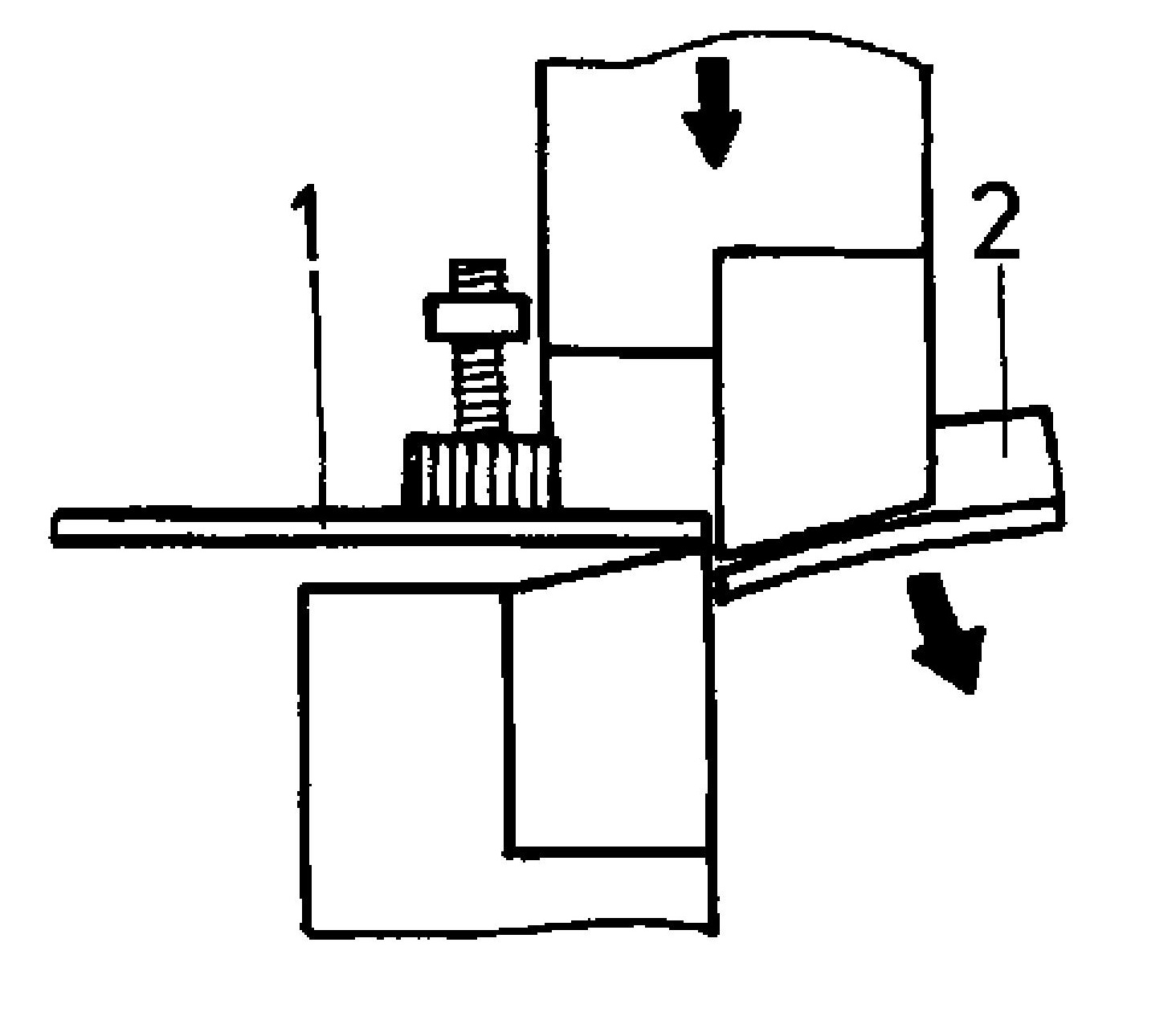
2.9Herramientas de corte (punzón y matriz)
Se utiliza para cortes repetidos e idénticos en producción. El punzón encaja con precisión en la placa de corte con una holgura de 0,05 a 0,1 mm, según el espesor de la chapa.
Lectura recomendada:Solución de problemas de perforación: consejos de alineación, espacio libre y seguridad
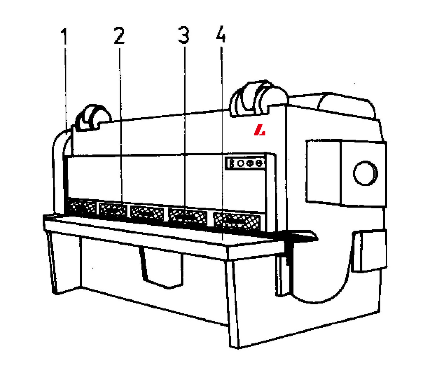
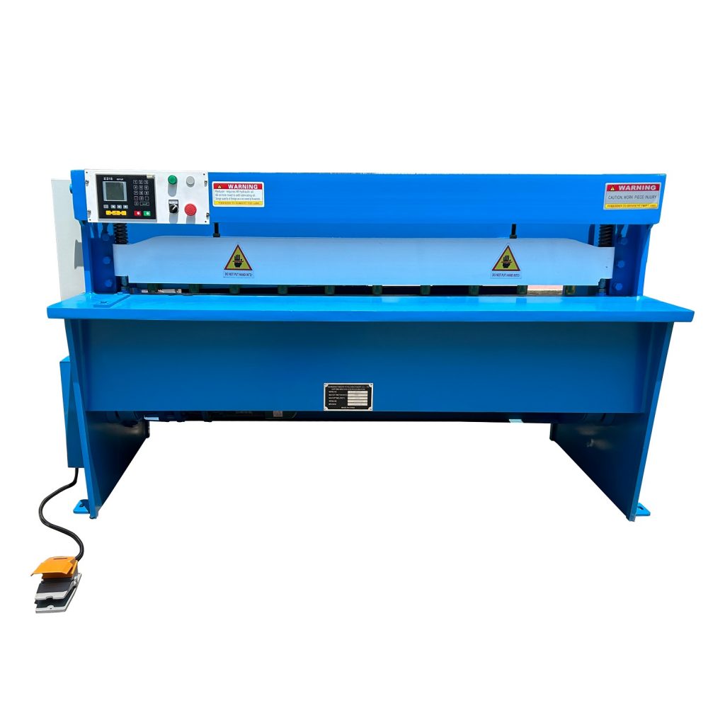
2.10Máquina cizalla accionada por motor
Para chapas muy largas o gruesas (más de 10 mm) y secciones resistentes. Incluye un potente accionamiento, una barra de sujeción hidráulica y ajuste de la separación de las cuchillas.
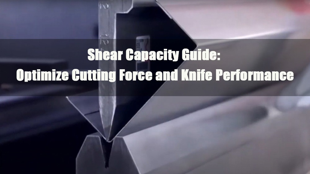
3.0Construcción y principios de funcionamiento de las tijeras
Las cizallas están diseñadas para soportar altas fuerzas de corte. Las consideraciones técnicas clave incluyen:
- Ángulo de cuña de la hoja: aprox. 80°, para mayor estabilidad
- Ángulo de separación: 2°–3°, reduce la fricción
- Espacio entre cuchillas: 0,05–0,1 mm × espesor de la hoja, para garantizar cortes limpios
Una separación inadecuada entre las cuchillas puede generar bordes desiguales o hojas dobladas.
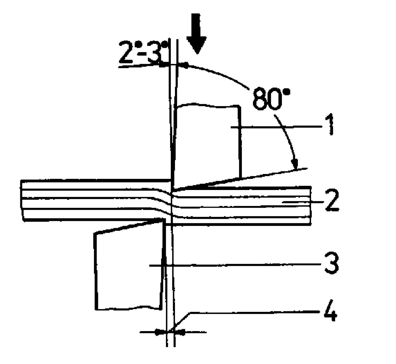
Un espacio excesivo provoca un acabado superficial deficiente y la deformación de la chapa.
El uso de una barra de sujeción correctamente ajustada evita el movimiento de la hoja.
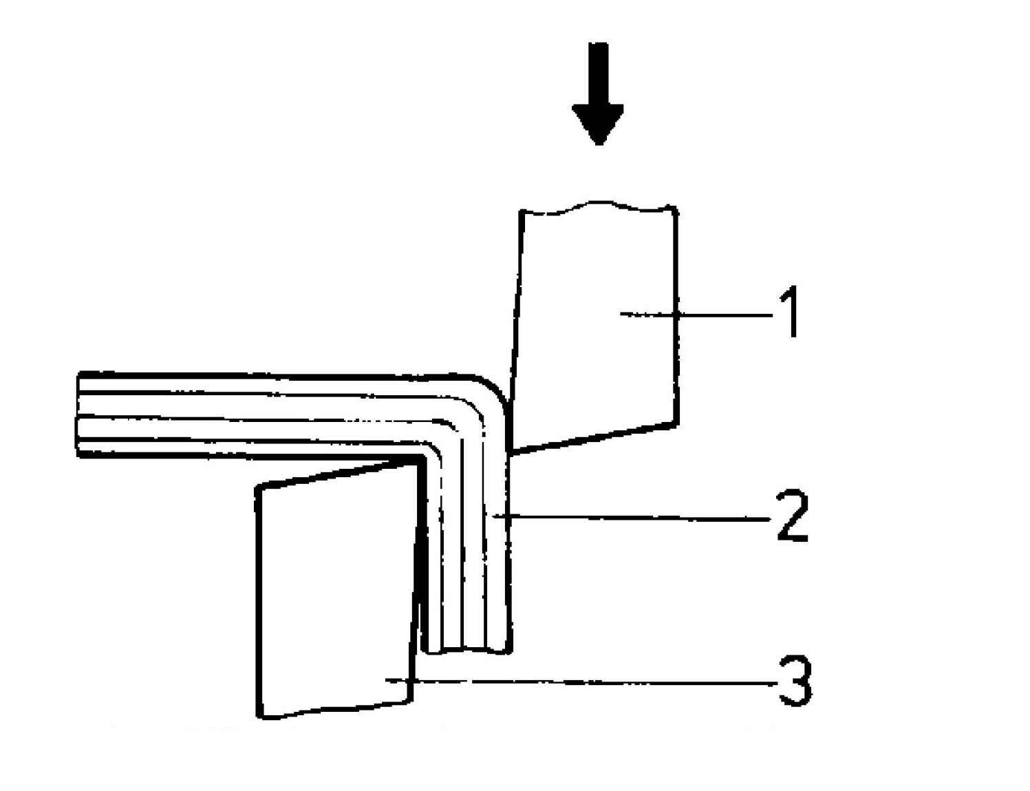
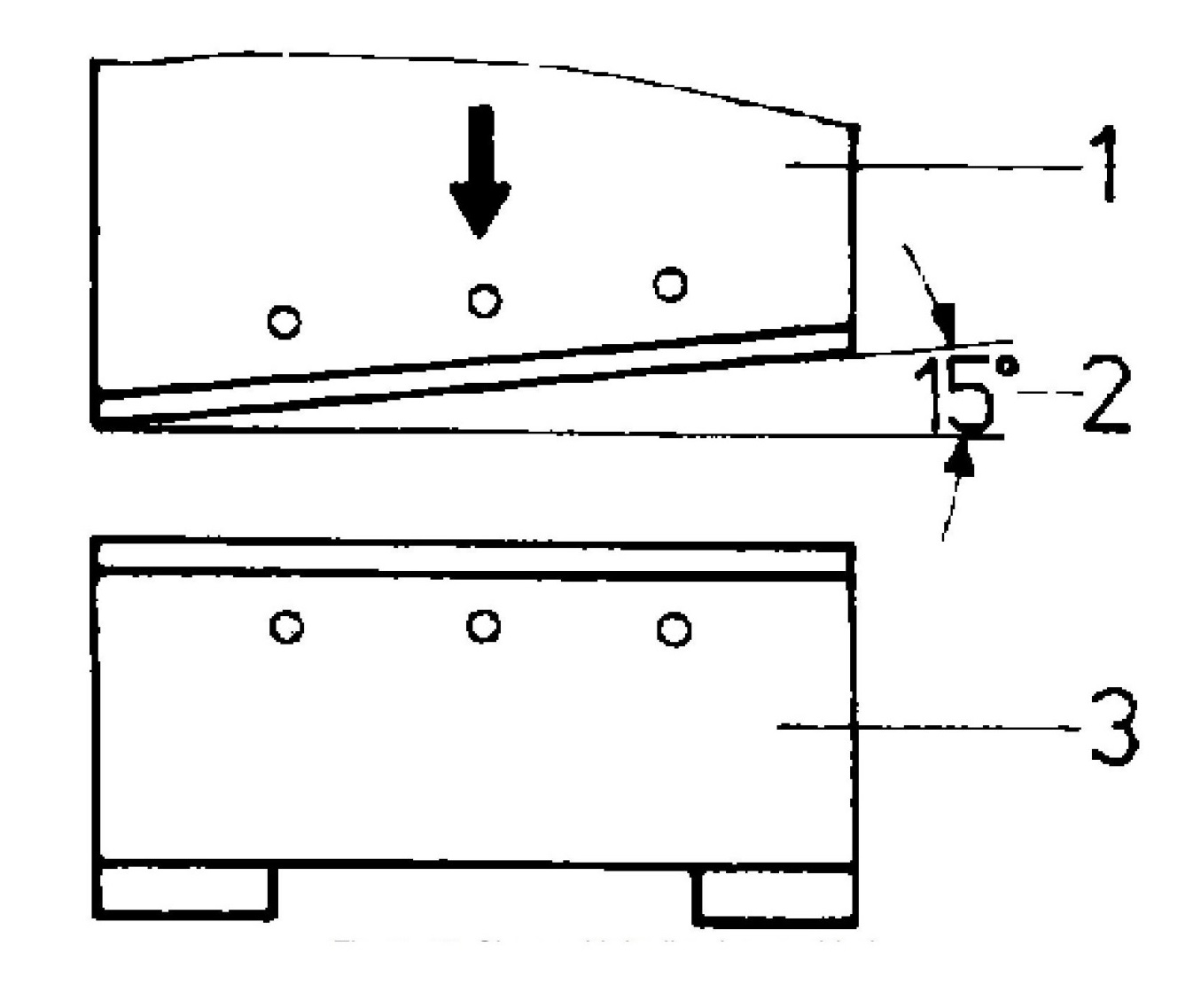
Las cuchillas paralelas cortan todo el filo a la vez, lo que requiere mayor fuerza. La mayoría de las máquinas utilizan una cuchilla superior inclinada para reducir la fuerza de corte necesaria.
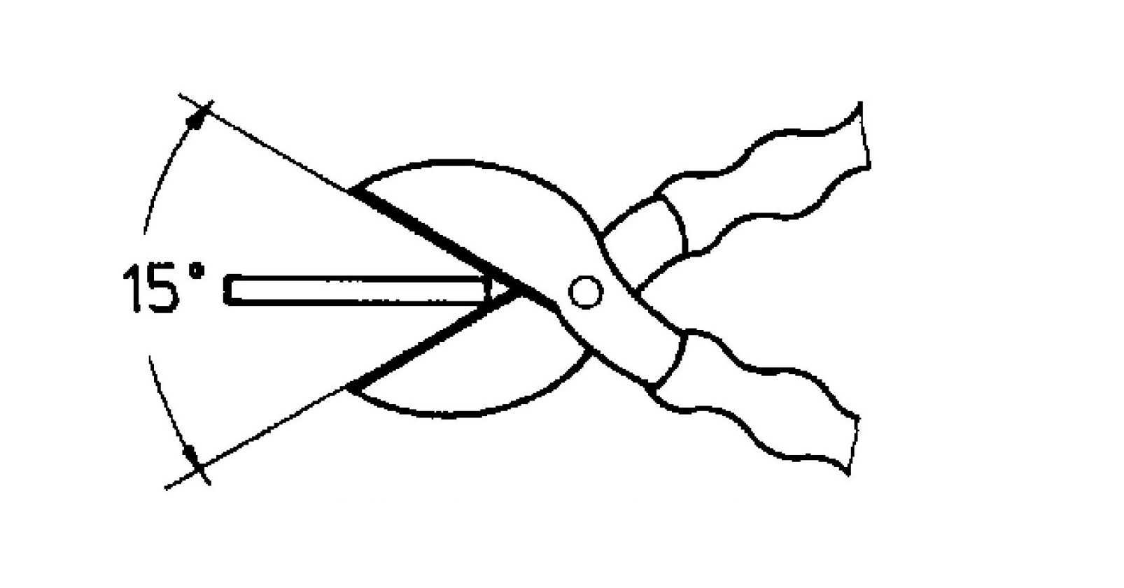
Introducir la pieza de trabajo profundamente en la cizalla aumenta el apalancamiento, pero también el riesgo de deslizamiento. El ángulo de ataque de la cuchilla (~15°) es necesario para mantener la calidad del corte.
4.0El proceso de esquila: operación paso a paso
El proceso de esquila consta de tres etapas clave:
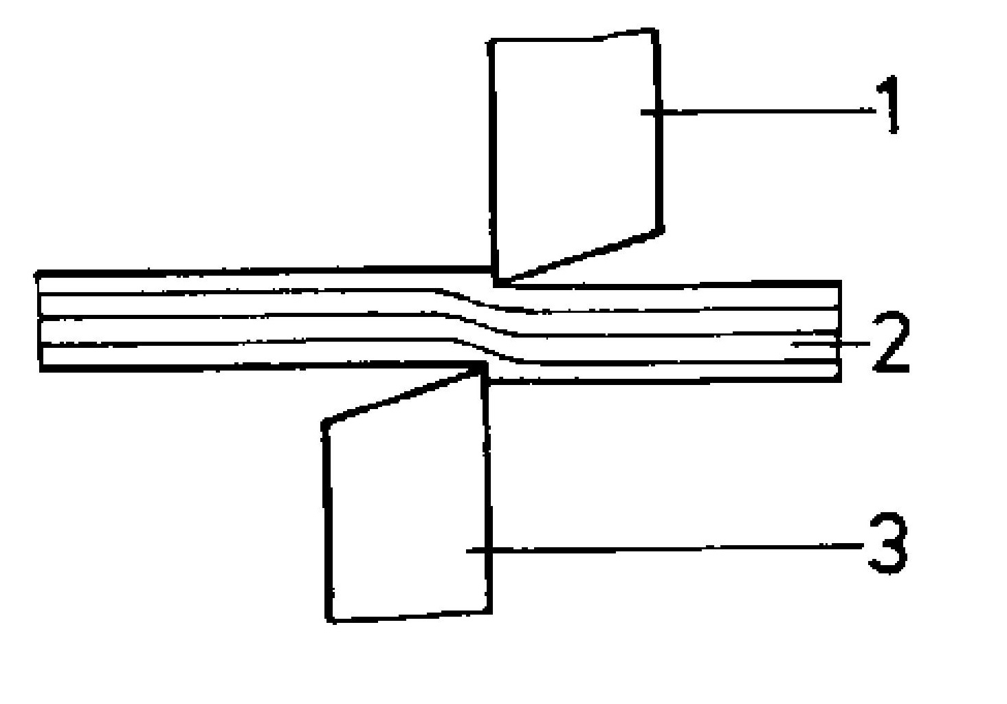
4.1Muescas
Sangría inicial del material cuando las cuchillas entran en contacto con la hoja.
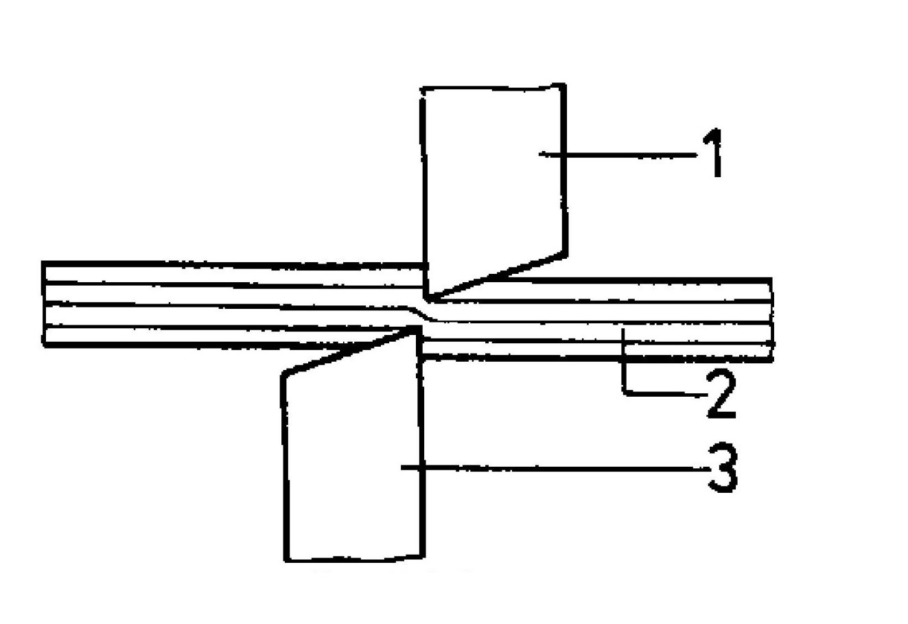
4.2Corte
Las cuchillas penetran y rompen la estructura metálica.
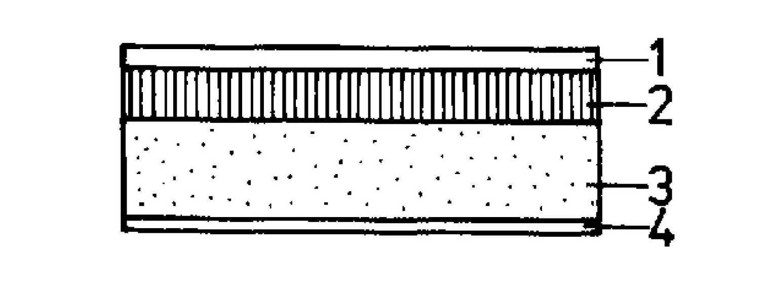
4.3Desgarro
Separación final del material por tensión interna y desgarro.

Estas etapas dejan zonas identificables en las caras cortadas de chapa gruesa.
5.0Técnicas de corte: métodos de corte y su uso
El cizallamiento se puede clasificar según el tipo y la extensión de la separación del material:
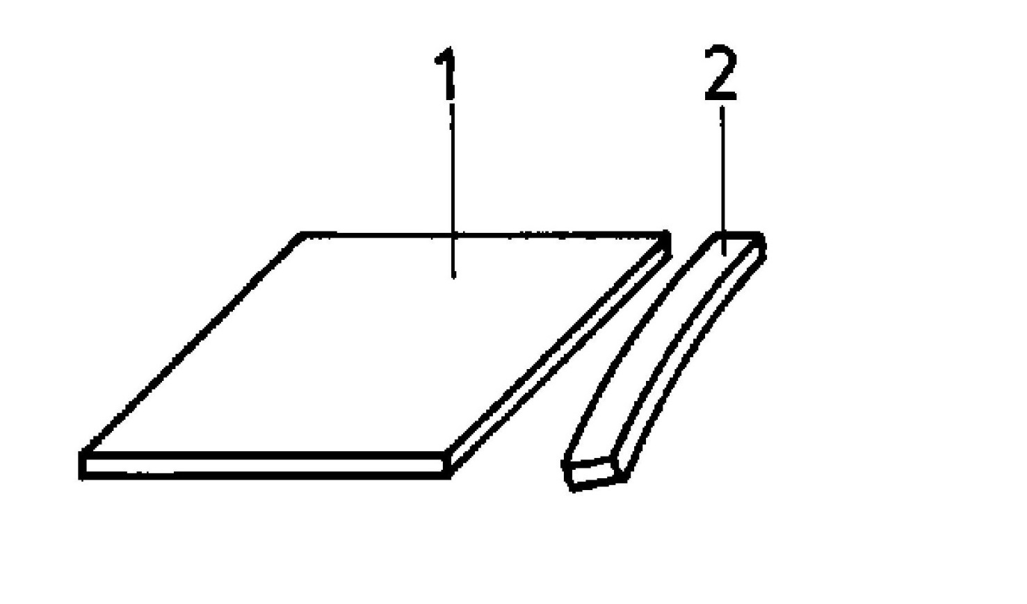
5.1Corte
Los cortes de profundidad parcial se utilizan para preparar la lámina para operaciones posteriores de doblado o plegado. El corte no atraviesa completamente el material, sino que lo debilita a lo largo de una línea para permitir una deformación precisa y controlada.

5.2Corte
Un corte completo que separa la pieza en dos secciones, generalmente para eliminar material no deseado como desecho. Es una acción básica de corte que se realiza con cizallas manuales o mecánicas.
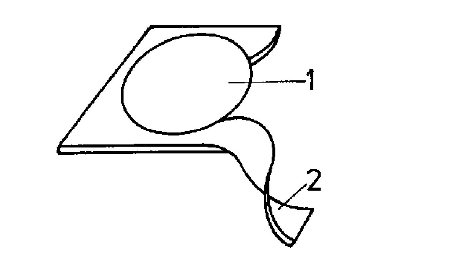
5.3Recorte
Esta técnica consiste en cortar a lo largo de un contorno cerrado, como un círculo o un rectángulo, donde la parte interior constituye la pieza deseada y la exterior se descarta. Se utiliza comúnmente para extraer formas funcionales de la lámina.
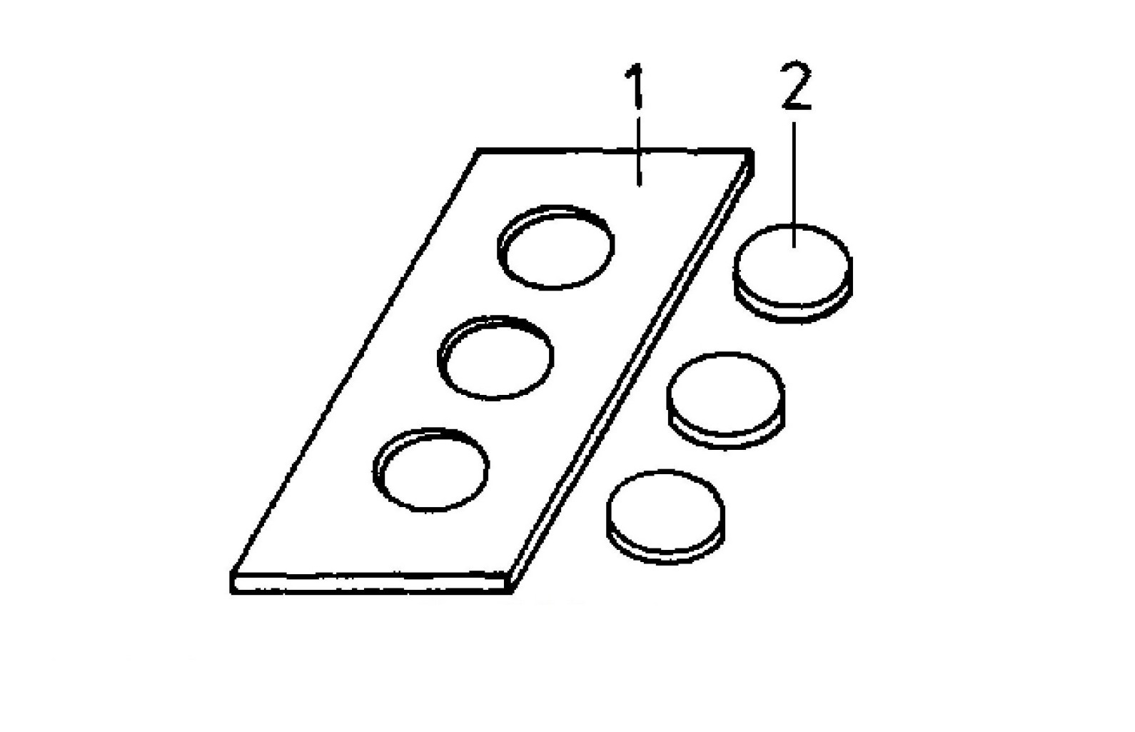
5.4Puñetazos
Al igual que el corte, el punzonado también sigue una trayectoria cerrada. Sin embargo, en el punzonado, la sección interior eliminada se considera desperdicio, y la chapa circundante restante forma la pieza de trabajo. Esta es una de las operaciones más comunes en el procesamiento industrial de chapa.
5.5Prensado integrado en la fabricación moderna
En los procesos de fabricación modernos, las prensas pueden realizar todas las técnicas de corte mencionadas (corte, descorte, corte y punzonado) utilizando conjuntos de punzones y matrices personalizados. Estas máquinas se utilizan comúnmente en la estampación con matriz progresiva. prensas hidráulicas, y Prensas de bastidor en C utilizado en la producción en masa.
Las máquinas de prensado ofrecen:
- Alta repetibilidad y consistencia
- Tiempos de ciclo reducidos
- Corte complejo de varias etapas en una sola pasada
- Integración con sistemas de alimentación y automatización
Esta integración los ha convertido en herramientas esenciales en sectores como la automoción, la fabricación de electrodomésticos y la electrónica.
6.0Procedimientos operativos: Realización de tareas de corte
6.1Cortar con tijeras de hojalatero
- Marcar la hoja con precisión
- Abra las mandíbulas a aproximadamente 15° y alinéelas con la línea.
- Cierre parcialmente la tijera, evitando rasgarla.
- Progresa paso a paso hasta alcanzar la longitud completa
6.2Corte con cizalla de palanca
- Marcar y alinear la hoja
- Ajuste la holgura de la cuchilla si es necesario
- Enganche la barra de sujeción y desbloquee la palanca
- Baje la cuchilla suavemente, evite un recorrido completo para evitar grietas.
- Bloquee la palanca después de cortar y retire la chatarra.
Coloque siempre el lado de la chatarra a la derecha de su línea de visión.
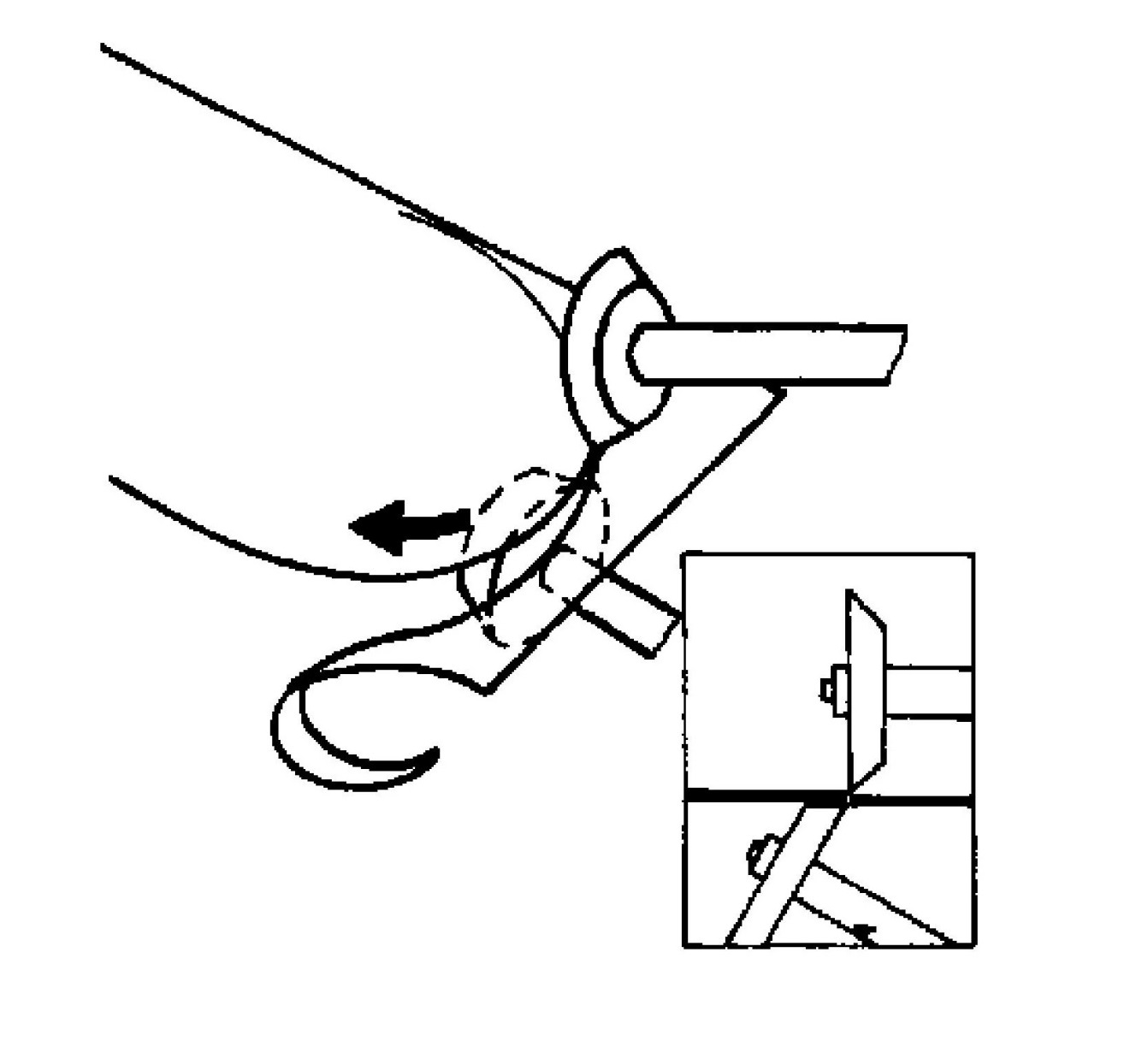
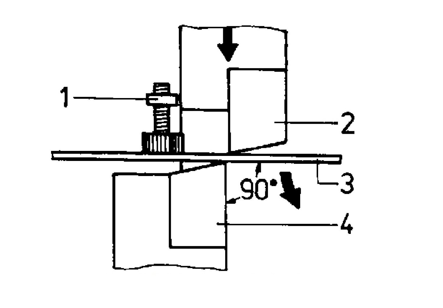
6.3Corte de secciones angulares con cizalla de palanca
- Marcar la superficie interior
- Insertar en la sección perfilada el portacuchillas
- Alinearse con la vanguardia
- Desbloquee y tire de la palanca hacia abajo con fuerza.
- Deseche los residuos inmediatamente

7.0Pautas de seguridad para operaciones de esquila
- Use guantes al manipular chapa metálica.
- Mantenga las manos alejadas del área de la cuchilla.
- Utilice únicamente herramientas debidamente mantenidas
- Asegure las palancas manuales después de cortar
- Utilice cuchillas seccionadoras para perfiles estructurales
- Siga todas las instrucciones de los fabricantes del equipo.
- Deseche los restos doblados o afilados inmediatamente para evitar lesiones.
8.0Preguntas frecuentes
¿Qué sucede si el espacio libre de la cuchilla es demasiado amplio?
Mala calidad de la superficie, rebabas y dobladuras de la chapa.
¿Por qué el ángulo de cuña de la cuchilla es tan grande?
Para garantizar la estabilidad y durabilidad del filo.
¿Cuál es la diferencia entre cortar y perforar?
Al recortar, se conserva la pieza interior; al perforar, la pieza interior es un desperdicio.
¿Por qué es importante un ángulo de inclinación de 15°?
Reduce la fuerza de corte requerida y mejora la calidad del corte.
¿Por qué es necesario cortar secciones estructurales con cuchillas seccionadoras?
Las hojas planas pueden astillarse o romperse al cortar secciones sólidas.
9.0Conclusión
El cizallamiento es un método rápido, eficiente y fiable para procesar chapa metálica y perfiles de acero. El dominio de la selección de herramientas, el ajuste de la máquina y los procedimientos de seguridad garantizan resultados de calidad y reducen el riesgo en la fabricación de metal.