
- 1.0What Is a Machine Tool Fixture?
- 2.0How Are Machine Tool Fixtures Classified?
- 3.0What Are the Basic Components of a Machine Tool Fixture?
- 4.0Core Principles of Workpiece Positioning
- 5.0Commonly Used Workpiece Positioning Elements
- 6.0How to Calculate V-Block Positioning Height and Relieved Pin Clearance
- 7.0How to Achieve Reliable Workpiece Clamping
- 8.0How to Select the Appropriate Machine Tool Fixture Based on Production Requirements
- 9.0Machine Tool Fixture Core FAQ (Frequently Asked Questions)
1.0What Is a Machine Tool Fixture?
During part machining on lathes, milling machines, drilling machines, spinning machines, stamping presses, and other metalworking equipment, the workpiece must first be placed in a correct and fixed position on the machine to ensure machining accuracy. This process involves two key steps:
- Accurately position the workpiece
- Securely clamp the workpiece
The complete process of positioning and clamping is referred to as workpiece setup, and the process equipment used to accomplish this setup is known as a machine tool fixture.
2.0How Are Machine Tool Fixtures Classified?
Machine tool fixtures can be classified from multiple perspectives, with the main classification methods as follows:
2.1Classification by Degree of Specialization
- General-purpose fixtures: Standardized fixtures that can be used to clamp different workpieces without adjustment or with only minor adjustments. Typical examples include three-jaw self-centering chucks, four-jaw independent chucks, machine vises, rotary tables, and dividing heads. These fixtures are mainly used for single-piece or small-batch production.
- Special-purpose fixtures: Fixtures specifically designed and manufactured for a particular machining operation of a specific workpiece. They feature compact structures and convenient operation, and are primarily used in high-volume, stable production, such as dedicated stamping fixtures for automotive body panels.
- Adjustable fixtures: Fixtures that can be adapted to machine workpieces of similar shape and size by adjusting or replacing certain components after one type of workpiece has been processed. They are commonly used in small- to medium-batch production.
- Modular fixtures: Fixtures assembled according to specific process requirements using a set of pre-manufactured standard components and elements. After use, they can be disassembled or reconfigured. Their advantages include shortened production cycles and reduced variety and quantity of special fixtures, making them suitable for new product trials and multi-variety, small-batch production.
- Transfer fixtures: Fixtures used in automated production lines for specific workpieces. In addition to clamping the workpiece, they also perform the function of transporting the workpiece along the automatic line.
2.2Classification by Machine Tool Type
- Lathe fixtures
- Milling machine fixtures
- Drilling machine fixtures
- Boring machine fixtures
- Spinning machine fixtures
- Stamping press fixtures
- Other machine tool fixtures
2.3Classification by Power Source
- Manual fixtures
- Pneumatic fixtures
- Hydraulic fixtures
- Electromagnetic fixtures
- Similar types
3.0What Are the Basic Components of a Machine Tool Fixture?
Although machine tool fixtures vary in form and application, their basic components are largely the same. Taking CNC milling fixtures for connecting rod slot milling, drilling fixtures for hole machining, and sheet metal fixtures for stamping presses as examples, the core components are described below. These fixtures share similar basic structures, with differences mainly in positioning and clamping elements to suit different machines:
- Positioning Device
- Composed of positioning elements and their combinations
- Used to determine the correct position of the workpiece within the fixture
- Typical examples include cylindrical pins and diamond-shaped pins
- Clamping Device
- Used to secure the workpiece in its predetermined position, ensuring it does not move under external forces during machining
- Typically includes clamping elements, transmission mechanisms, and power components, such as pressure plates, nuts, washers, bolts, and springs
- Fixture Body
- The base component that connects all fixture elements and devices into a rigid, integrated structure
- Ensures the overall accuracy and stiffness of the fixture
- Other Elements and Devices
- Include locating keys, operating components, and standardized connecting elements
- Fixtures used on general-purpose machine tools may also be equipped with tool-setting devices and indexing mechanisms
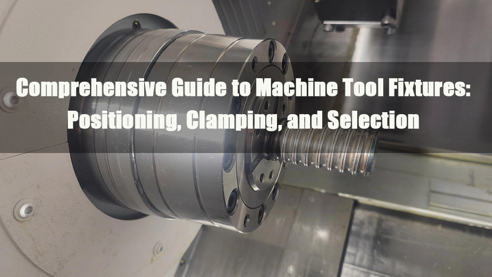
Note:Structure of the connecting rod slot milling fixture (Figure 1-27):
- Fixture body
- Pressure plate
- Nuts
- Washers
- Bolt
- Spring
- Locating key
- Diamond pin
- Cylindrical pin
4.0Core Principles of Workpiece Positioning
4.1What Is the Fundamental Principle of Workpiece Positioning?
The Six-Point Positioning Principle
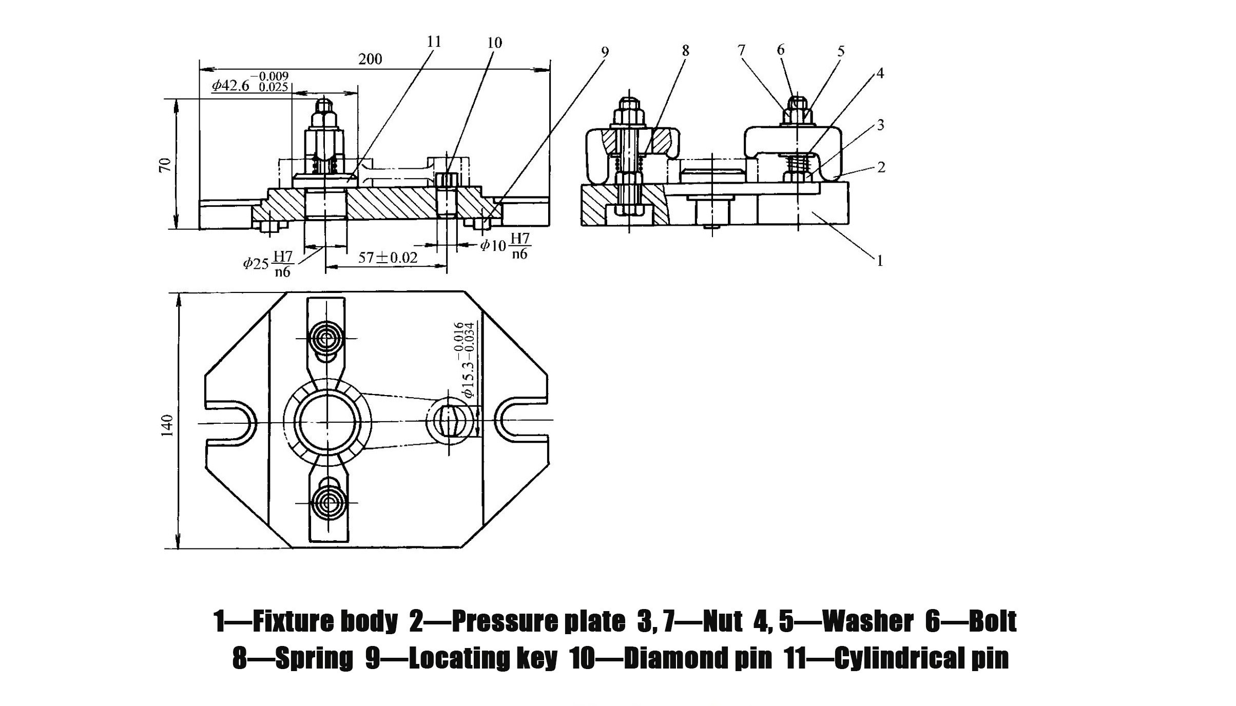
- A workpiece in space has six degrees of freedom: three translational degrees of freedom along the x, y, and z axes, and three rotational degrees of freedom about the x, y, and z axes (Figure 1-28)
- To fully determine the position of a workpiece, six support points (positioning elements) must be arranged as required to restrict these six degrees of freedom, with each support point restricting one corresponding degree of freedom
- This concept is known as the six-point positioning principle
- Application cases for different workpieces:
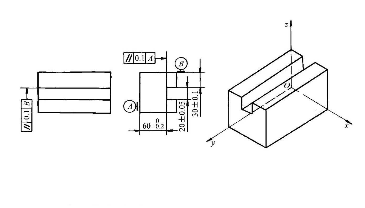
- Rectangular workpieces: When machining planes on a planer or milling slots on a milling machine, the bottom surface A is placed on three support points that are not collinear, restricting three degrees of freedom; the side surface B contacts two support points arranged along the length direction, restricting two degrees of freedom; the end surface C contacts one support point, restricting one degree of freedom (Figure 1-29)
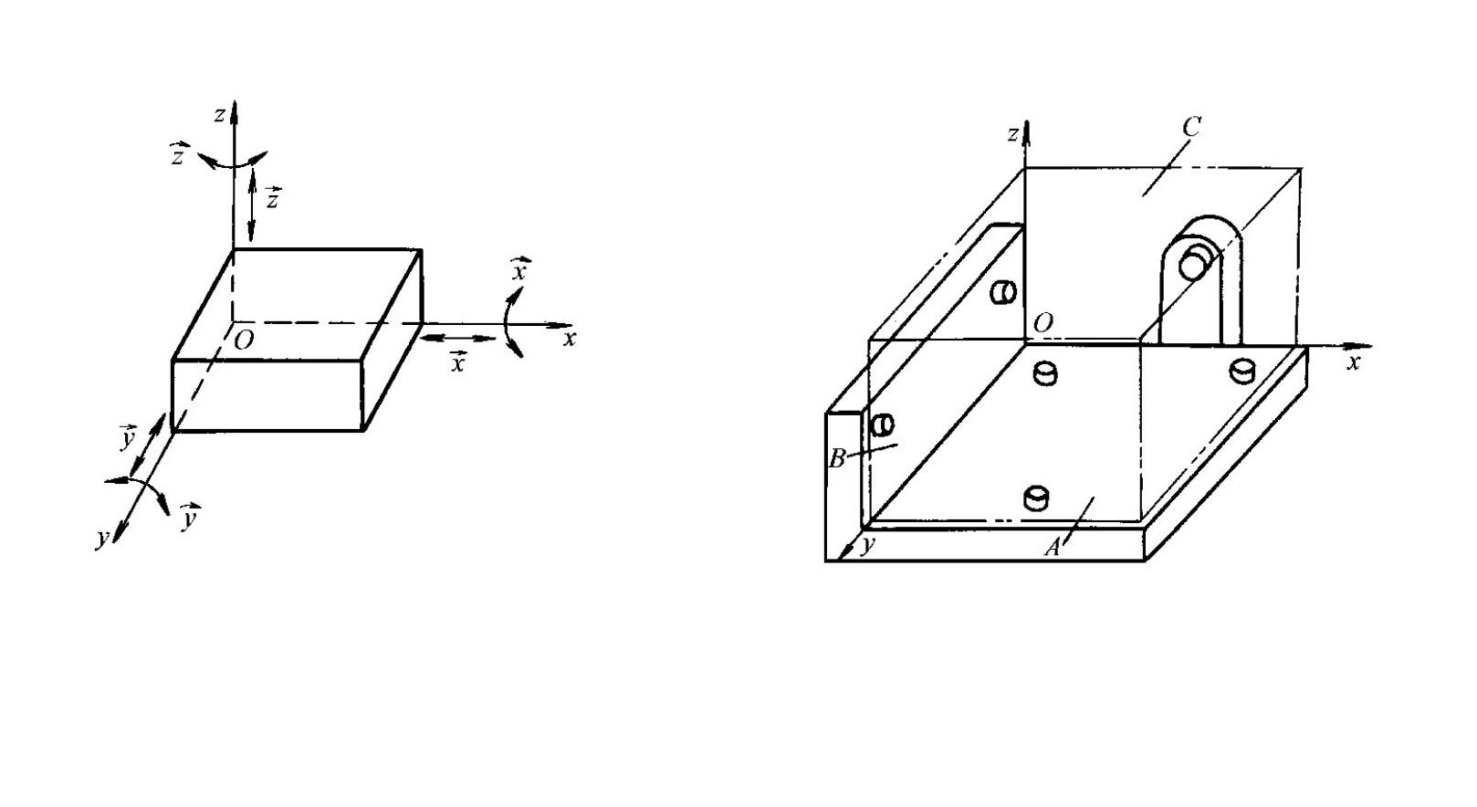
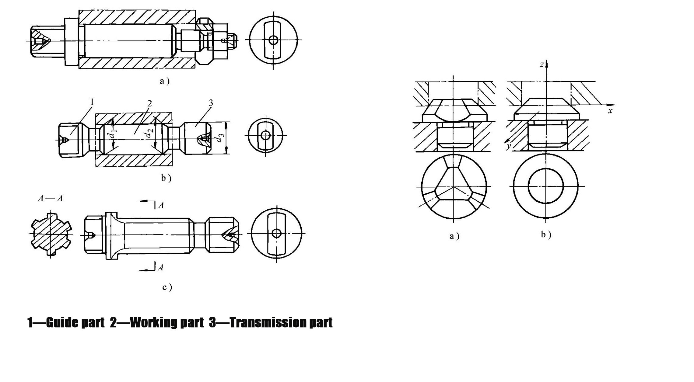
- Disc-shaped workpieces: During external cylindrical grinding on a grinder or forming on a spinning machine, the planar surface rests on three support points, restricting three degrees of freedom; the cylindrical surface contacts two side support points, restricting two degrees of freedom; one side surface of the slot contacts a single support point, restricting one degree of freedom (Figure 1-30)
Relationship Between Restricted Degrees of Freedom and Machining Requirements
- Degrees of freedom that affect machining requirements must be restricted
- Degrees of freedom that do not affect machining accuracy need not be restricted
- Example: When milling a through-slot as shown in Figure 1-31 or drilling holes on a drilling machine to ensure hole perpendicularity, five degrees of freedom influence the machining requirements, while one does not and may remain unrestricted
Classification of Positioning Methods
- Complete positioning: All six degrees of freedom of the workpiece are restricted (Figures 1-29 and 1-30); this method is suitable for operations with high accuracy requirements
- Incomplete positioning: Fewer than six degrees of freedom are restricted, but machining requirements are still satisfied (Figure 1-31); this is the most commonly used positioning method in practical machining
- Under-positioning: Degrees of freedom that should be restricted according to machining requirements are not restricted, making it impossible to guarantee machining accuracy; this method is strictly prohibited; for example, in Figure 1-31, if a degree of freedom affecting dimensional accuracy or parallelism is not restricted, the corresponding machining requirement cannot be ensured
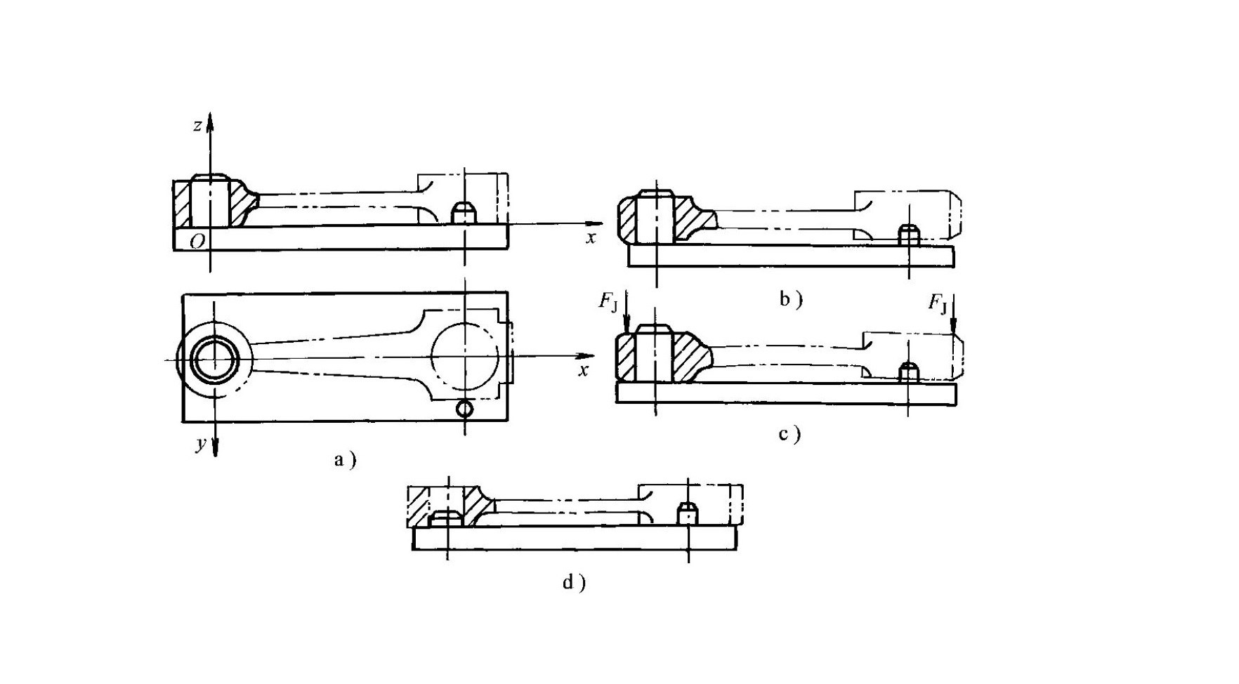
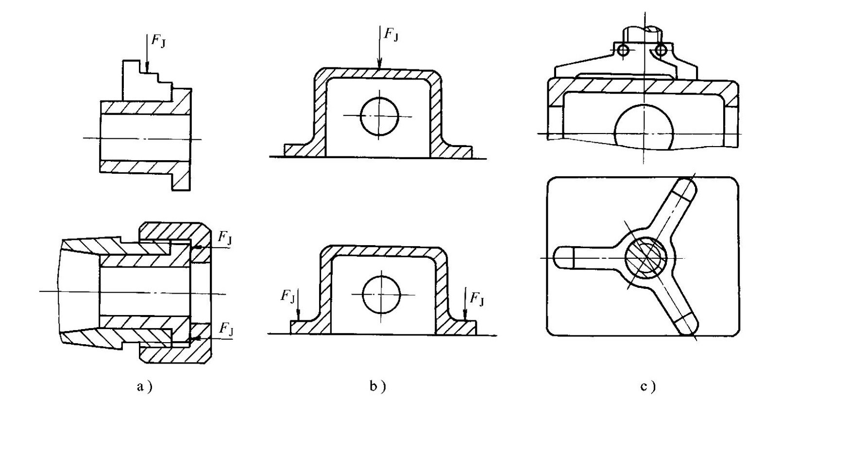
- Over-positioning: One or more degrees of freedom of the workpiece are repeatedly restricted by different positioning elements; in the connecting rod positioning scheme shown in Figure 1-32a, the long pin and support plate repeatedly restrict two degrees of freedom, which may cause deformation of the workpiece or the pin and affect machining accuracy; replacing the long pin with a short pin can eliminate over-positioning (Figure 1-32d)
- Judgment standard for over-positioning: Must be analyzed case by case; if it causes deformation, it must not be used; if it does not affect positioning and helps improve accuracy, it may be adopted appropriately
4.2What Is the Difference Between a Locating Datum and a Locating Surface?
- Locating Datum
- A reference on the workpiece used to determine its correct position
- May be a point, a line, or a surface
- In some cases is a virtual element that does not physically exist, such as the axis of a hole or shaft, or the symmetrical center plane between two surfaces
- Locating Surface
- The physical carrier of the locating datum
- The actual surface of the workpiece that directly contacts the positioning elements
- Typical examples for distinction:
- Example 1: When a workpiece is positioned by a hole, the locating datum is the hole’s axis (virtual), while the locating surface is the inner surface of the hole (actual contact surface)
- Example 2: When a workpiece is positioned by a plane, the locating datum and locating surface coincide and are the same plane
5.0Commonly Used Workpiece Positioning Elements
5.1Positioning Elements for Planar Location
- Primary supports (used for positioning and restricting degrees of freedom)
- Fixed supports
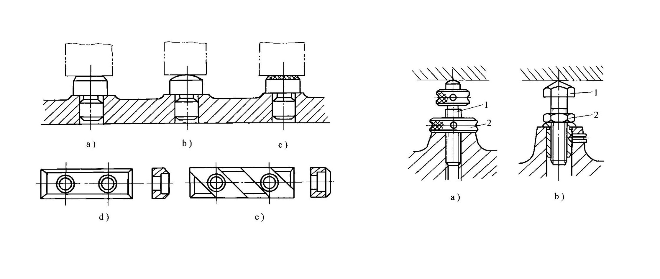
- Include support pins and support plates (Figure 1-33), which remain stationary during use
- Application scenarios for different types:
- Flat-head support pins (Figure 1-33a) or support plates (Figures 1-33d and 1-33e) are used for positioning on a machined plane
- Ball-head support pins (Figure 1-33b) are used for locating on rough surfaces
- Serrated-head support pins (Figure 1-33c) are used for side-surface positioning to increase friction and prevent workpiece slippage
- Characteristics of different support plates:
- The support plate shown in Figure 1-33d has a simple structure and is easy to manufacture, but chips near holes are difficult to remove; it is suitable for side and top surface positioning
- The support plate in Figure 1-33e allows easy chip removal and is suitable for bottom surface positioning
- Adjustable supports
- Used when the height of the support pin needs adjustment (Figure 1-34)
- Adjustment steps: Loosen the lock nut 2, set the adjusting pin 1 to the required height, and then tighten the lock nut 2
- Mainly used for rough positioning when workpiece blank size and shape vary significantly
- Self-aligning supports (floating supports)
- Automatically adjust their position during positioning until all contact points touch the workpiece (three-point type in Figure 1-35a and two-point type in Figure 1-35b)
- Their function is equivalent to a single positioning support point, restricting only one degree of freedom
- Improve workpiece rigidity and stability
- Suitable for machining thin steel plates with insufficient rigidity, such as on stamping presses
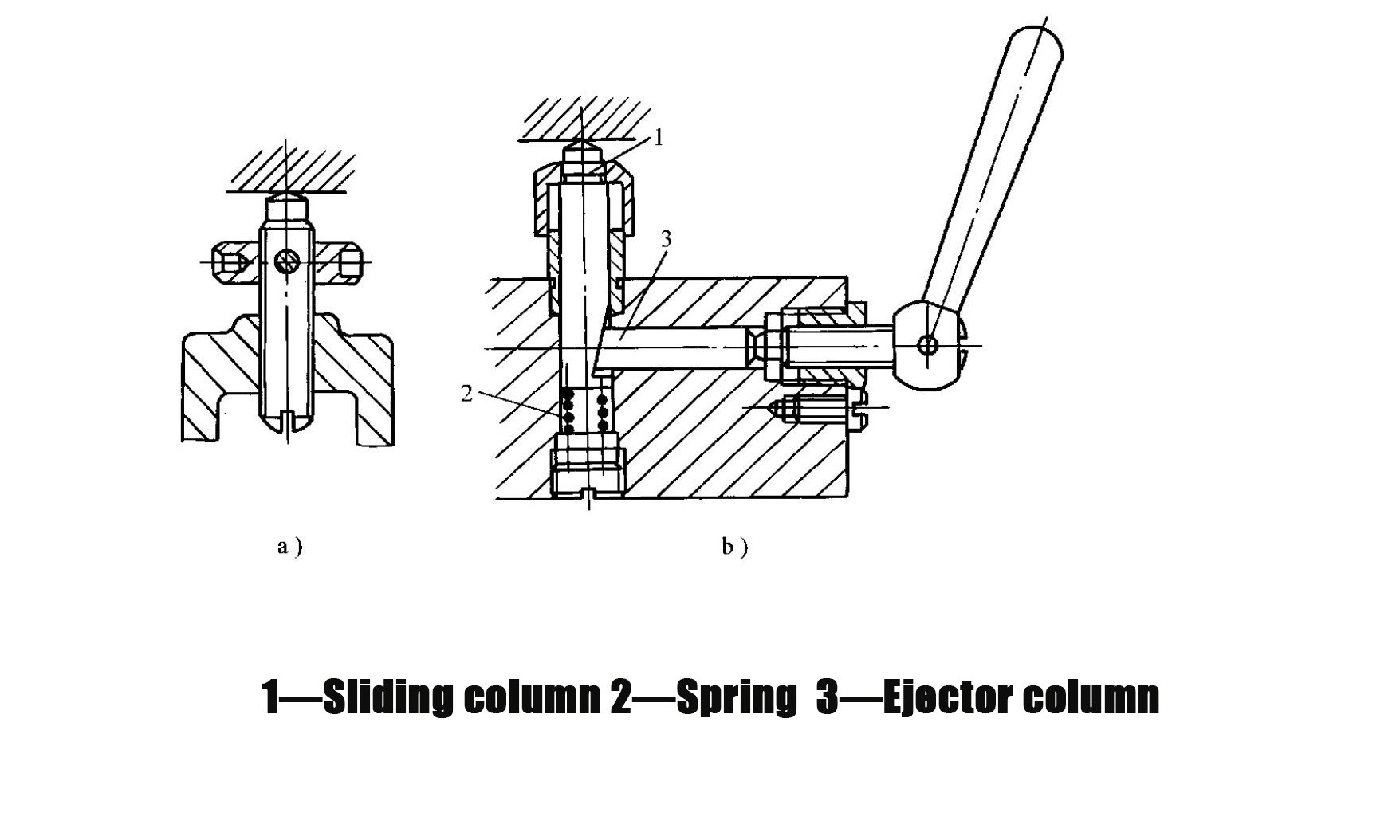
- Auxiliary supports
- Used to improve clamping rigidity and stability without performing a positioning function and without affecting the original positioning (Figure 1-36)
- Characteristics of different structures:
- The structure in Figure 1-36a is simple but inefficient
- Figure 1-36b shows a spring-loaded self-aligning auxiliary support, where the spring 2 pushes the sliding column 1 into contact with the workpiece, and the support rod 3 locks it in place
5.2Positioning Elements for External Cylindrical Surface Location
- Support positioning
- The most commonly used method is V-block positioning (Figure 1-37)
- Application scenarios for different V-block types:
- Figure 1-37a is used for precision datum positioning of short workpieces (machined surfaces)
- Figure 1-37b is used for rough datum positioning of long workpieces (unmachined surfaces)
- Figure 1-37c is used for positioning two precision datums that are far apart
- Special V-block for large locating datum length: V-blocks with cast iron bases and hardened steel inserts are used (Figure 1-37d)
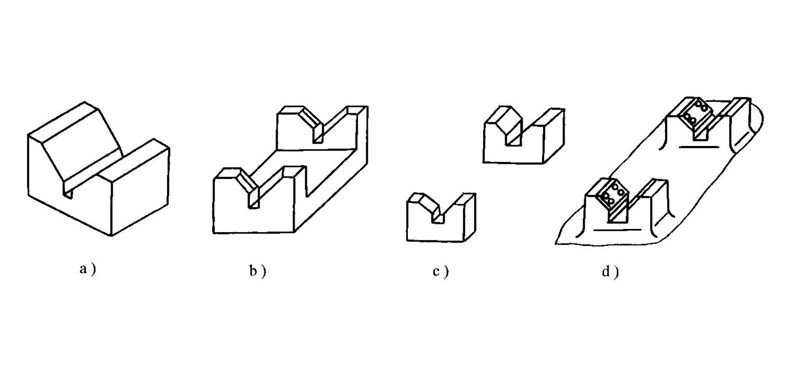
- Degree of freedom restriction: Long V-blocks restrict four degrees of freedom, while short V-blocks restrict two degrees of freedom
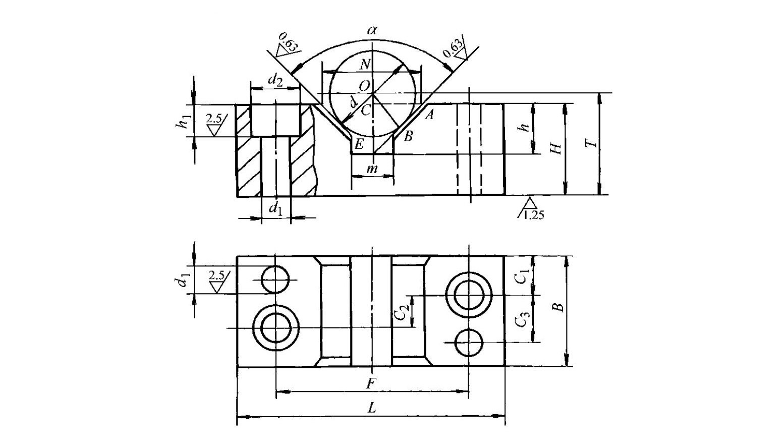
- Common V-block angles: 60°, 90° (most common), and 120°
- Standardization: V-block structures have been standardized (Figure 1-38), and most parameters can be found in machine tool fixture design manuals
- Self-centering positioning
- Automatically positions the workpiece axis at the required location, such as three-jaw self-centering chucks and spring collets
- Sleeves can also be used as positioning elements (Figure 1-39)
- Degree of freedom restriction for sleeves:
- The short sleeve hole shown in Figure 1-39a is equivalent to two-point positioning and restricts two degrees of freedom
- The long sleeve hole shown in Figure 1-39b is equivalent to four-point positioning and restricts four degrees of freedom
5.3Positioning Elements for Hole-Based Location
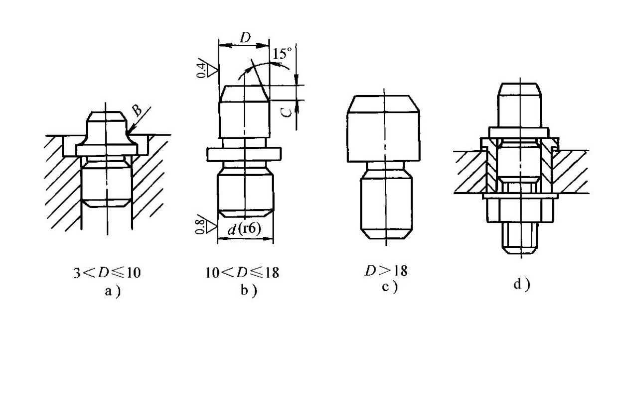
- Locating pins
- Common structures are shown in Figure 1-40
- Structural features:
- When the pin diameter D is 3–10 mm, a fillet radius R is provided at the root to prevent breakage or quenching cracks during heat treatment
- The fixture body is provided with a counterbore so that the pin is recessed and does not affect positioning
- For mass production, bushing-type structures (Figure 1-40d) are used to facilitate replacement
- The pin head has a 15° chamfer to ease workpiece loading
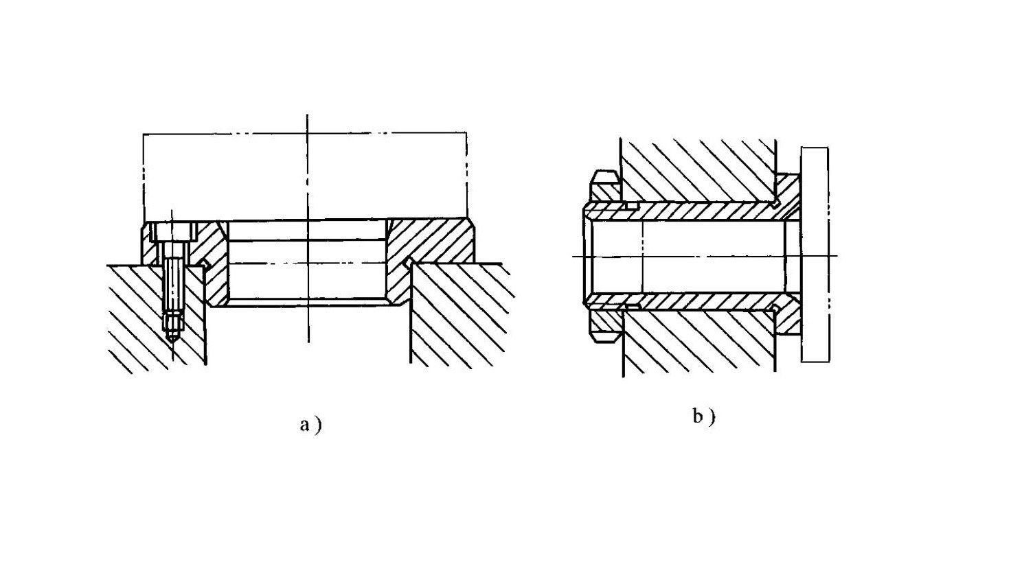
- Cylindrical mandrels
- Typical structures are shown in Figure 1-41
- Characteristics of different mandrel types:
- Figure 1-41a shows a clearance-fit mandrel, which allows easy loading and unloading but offers moderate centering accuracy
- Figure 1-41b shows an interference-fit mandrel consisting of a guide section, working section, and drive section; it is simple in structure, provides high centering accuracy, and requires no additional clamping device, but loading and unloading are inconvenient and may damage the locating hole; it is mainly used for precision machining with high centering accuracy requirements
- Figure 1-41c shows a spline mandrel used for machining workpieces located by spline holes
- Taper pins
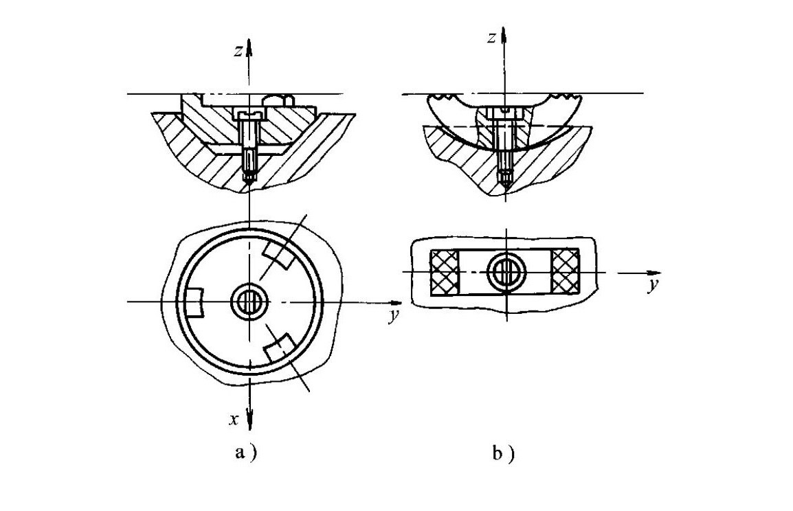
- When a workpiece is positioned by a hole on a taper pin (Figure 1-42), three degrees of freedom are restricted
- Application scenarios: Figure 1-42a is used for rough datum positioning, while Figure 1-42b is used for precision datum positioning
- Taper mandrels (small-taper mandrels)
- As shown in Figure 1-43, the workpiece is positioned on a taper mandrel and clamped by elastic deformation between the locating hole and the limiting taper surface of the mandrel
- Performance characteristics: Provides high centering accuracy (up to φ0.01–φ0.02 mm), but axial positioning error is relatively large
- Application scope: Suitable for precision turning, grinding, and spinning operations where the locating hole accuracy is no lower than IT7; end faces cannot be machined using this method
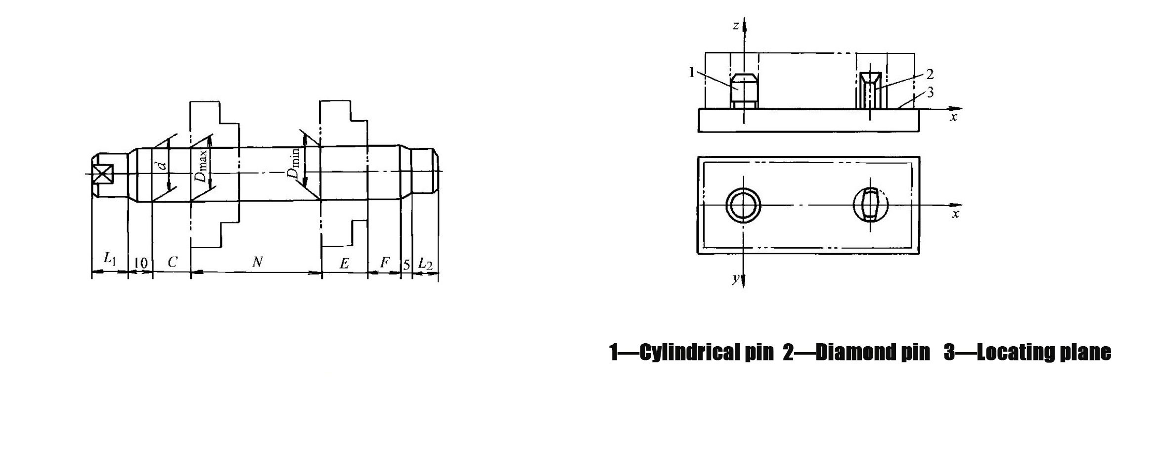
5.4Positioning by One Plane and Two Holes
- The positioning scheme is shown in Figure 1-44, where one large plane of the workpiece and two holes perpendicular to that plane are used as locating datums
- Over-positioning problem: When the fixture uses one planar support (restricting three degrees of freedom) and two cylindrical pins (each restricting two degrees of freedom), over-positioning occurs in the direction of the line connecting the two pins
- Solution: To avoid over-positioning, one of the pins must be designed as a relieved pin that does not restrict the x-direction degree of freedom
- Reference standard: The dimensions of the relieved pin can be selected with reference to Table 1-5
6.0How to Calculate V-Block Positioning Height and Relieved Pin Clearance
6.1Calculation of V-Block Positioning Height T
- Formula: T=H+(d−N/2)/tan(α/2)
- Symbol definitions:
- H: Height of the V-block
- d: Design mandrel diameter of the V-block
- N: Opening width of the V-block
- α: Included angle between the two working faces of the V-block
- Application purpose: This formula is used to determine the vertical positioning height of a workpiece axis relative to the reference surface of the fixture when using a V-block for cylindrical surface location
6.2Calculation of Minimum Fit Clearance Xmin Between Relieved Pin and Hole
- Formula: Xmin=(TLD+TLd)×(D/2)/L
- Symbol definitions:
- TLD: Tolerance of the center distance between the two locating holes
- TLd: Tolerance of the center distance between the two locating pins
- D: Diameter of the hole mating with the relieved pin
- L: Center distance between the two locating holes (or locating pins)
- Application purpose: This calculation ensures that the relieved pin does not cause over-positioning while still meeting positioning accuracy requirements
Note:Structural dimensions of relieved pins (Table 1-5, unit: mm):
| Pin Diameter D (mm) | Parameter b (mm) | Parameter B (mm) |
| 3–6 | 2 | D−0.5 |
| >6–8 | 3 | D−1 |
| >8–20 | 4 | D−2 |
| >20–25 | 5 | D−3 |
| >25–32 | 6 | D−4 |
| >32–40 | 7 | D−5 |
| >40–50 | 8 | D−5 |
These recommended dimensions are commonly used in fixture design to balance positioning accuracy and assembly reliability.
7.0How to Achieve Reliable Workpiece Clamping
7.1Basic Requirements for Clamping Devices
- During the clamping process, the correct position of the workpiece after positioning must not be altered
- The clamping force must be appropriate: it should ensure stable positioning and minimal vibration during machining, while avoiding excessive clamping deformation of the workpiece
- Operation should be convenient, labor-saving, and safe
- The level of automation and structural complexity of the clamping device should match the production volume and batch size of the workpiece
7.2How to Select the Direction and Point of Application of Clamping Force
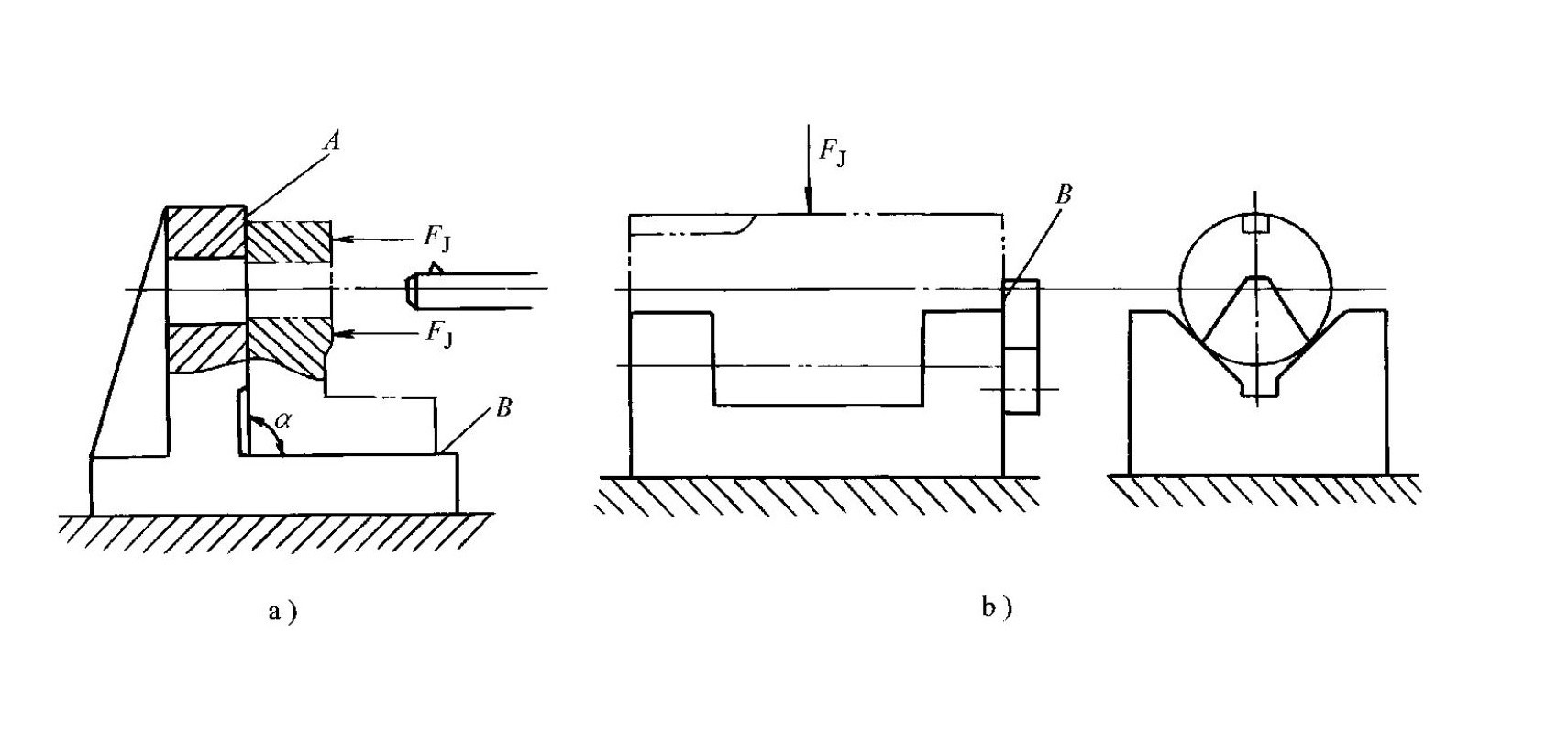

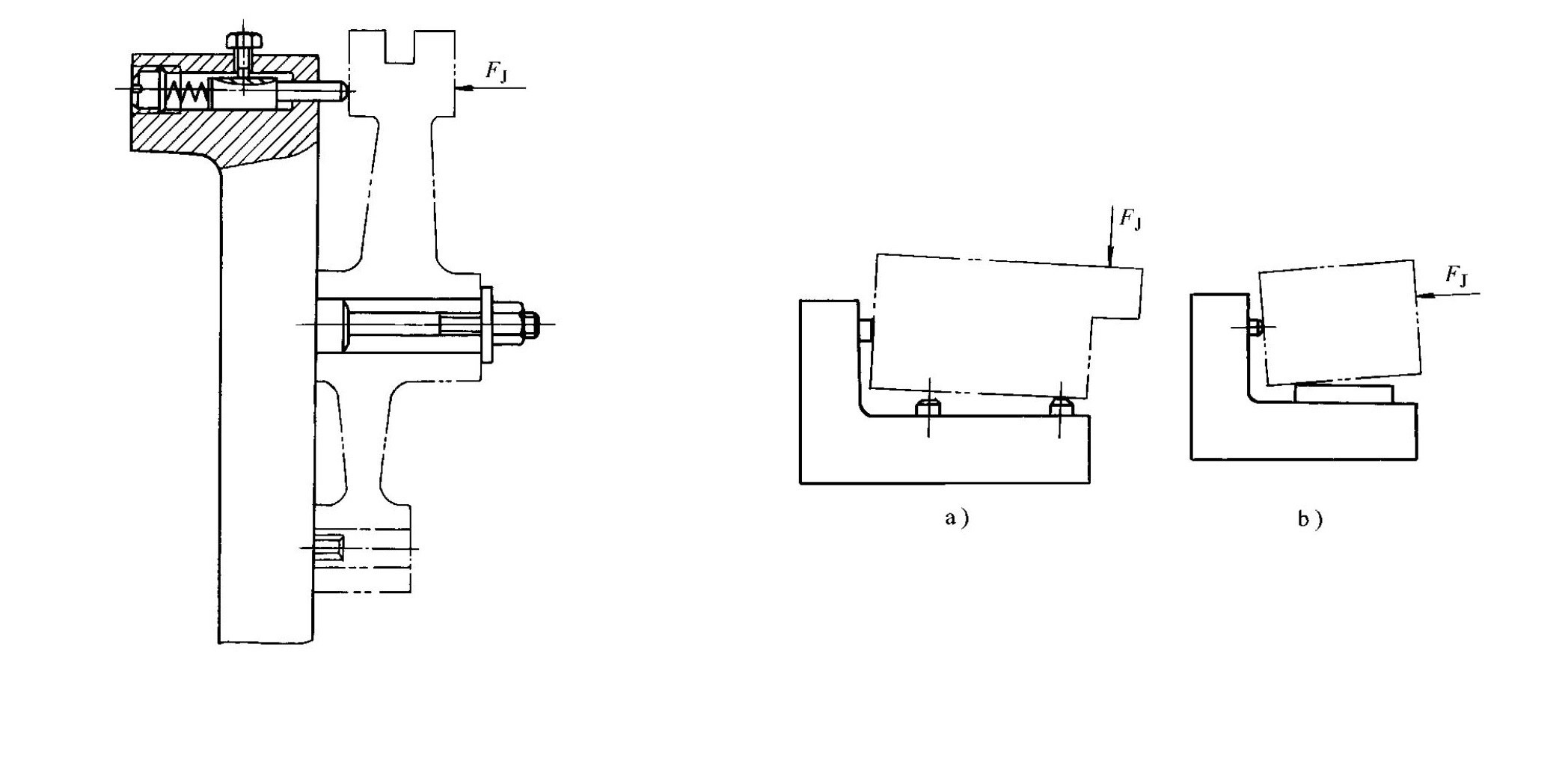
- Clamping force should act toward the primary locating surface (Figure 1-45)
- Practical case: When a perpendicularity requirement exists between the machined hole and the left end face, the clamping force FJ must act toward locating surface A; if it acts toward surface B instead, angular errors between the left end face and the bottom surface may destroy the positioning and affect the perpendicularity between the hole and the left end face
- The direction of the clamping force should help minimize the required clamping force (Figure 1-46)
- Practical case: When the clamping force FJ acts in the same direction as the cutting force F and the workpiece weight W, the required clamping force is minimized
- The point of application of the clamping force should be chosen at locations and in directions with higher workpiece rigidity (Figure 1-47)
- Practical cases:
- For thin-walled sleeves during turning on a lathe or forming on a spinning machine, axial rigidity is greater than radial rigidity; radial clamping causes larger deformation, so applying the clamping force in the axial direction reduces deformation
- When clamping thin-walled box-type parts, the force should act on stiff flanges; if no flange is available, single-point clamping can be replaced by three-point clamping (Figure 1-47c) to reduce clamping deformation
- The clamping force application point should be as close as possible to the machining surface (Figure 1-48)
- Practical case: When milling slots on a shift fork, the main clamping force is applied far from the machining surface; in this case, auxiliary supports should be added near the machining area and the clamping force FJ increased to improve setup rigidity and reduce machining vibration
- The line of action of the clamping force must fall within the range of the locating supports (Figure 1-49)
- Warning: If the line of action lies outside the support range, the workpiece positioning will be destroyed during clamping; this is an incorrect and unacceptable operation
7.3Methods for Estimating Clamping Force
The magnitude of the clamping force directly affects setup reliability, clamping deformation, positioning accuracy, and machining quality. Two commonly used estimation methods are as follows:
- Analogy method
- The clamping force is estimated by referring to the operating conditions of similar fixtures
- This method is widely used in production practice
- Static equilibrium method
- The fixture and workpiece are regarded as a rigid system
- The most unfavorable instantaneous condition during machining is identified, and the theoretical clamping force is calculated based on static equilibrium
- The result is then multiplied by a safety factor K (2.5–3 for rough machining, 1.5–2 for finish machining) to obtain the actual clamping force
- Typical calculation examples:
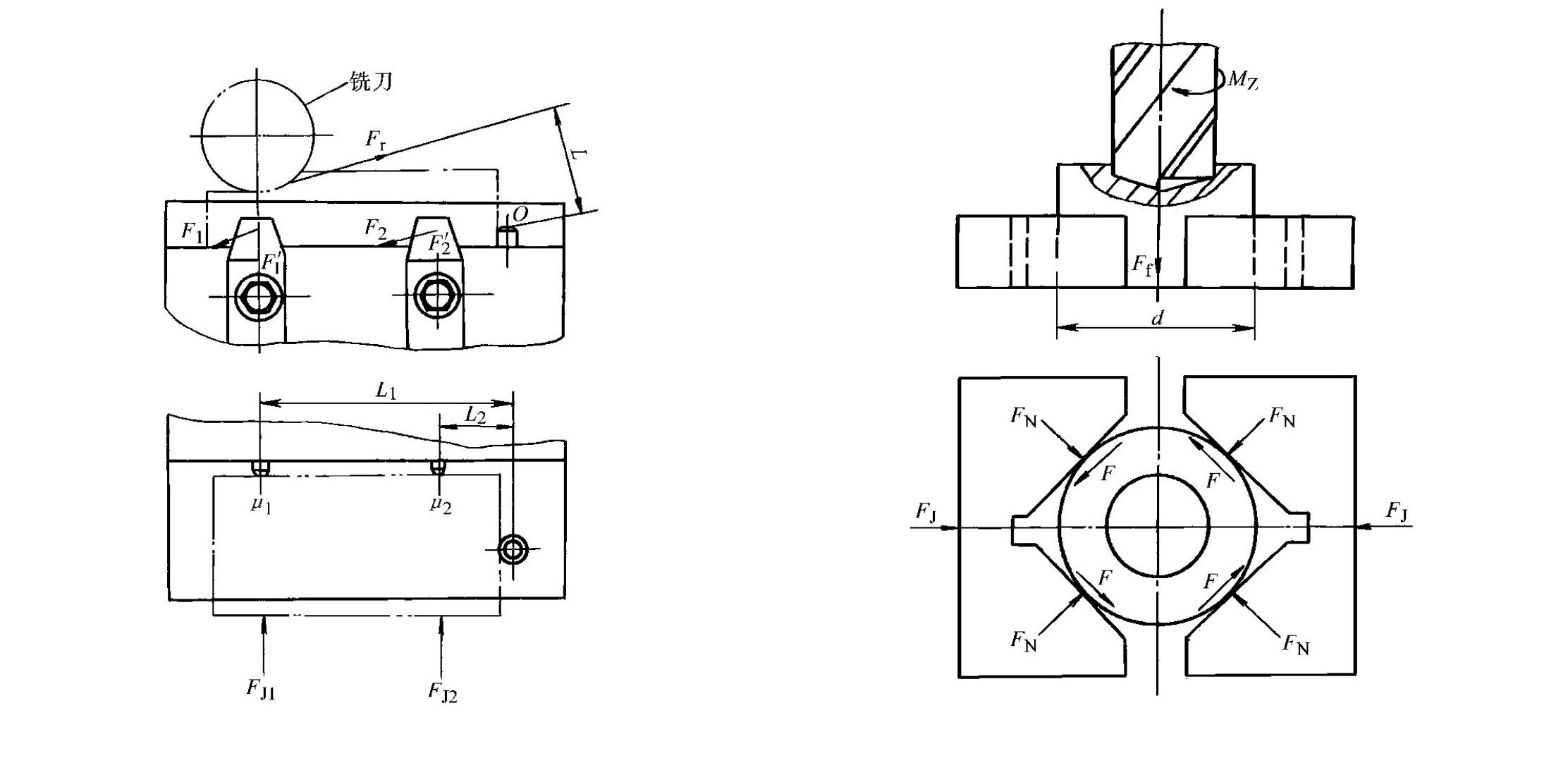
- Milling example (Figure 1-50): When the cutting force Fr reaches its maximum and the distance L from Fr to the stop pin O is the largest, the workpiece tends to rotate about point O; according to static equilibrium, assuming FJ1 = FJ2 = FJ and μ1 = μ2 = μ, the clamping force formula is FJ=Fr×L/[μ×(L1+L2)]; the actual clamping force is F=K×Fr×L/[μ×(L1+L2)](unit: N); where Fr is the maximum cutting force (N), μ is the friction coefficient between the workpiece and locating elements, L1 is the distance from the cutting force direction to the stop pin (mm), and L2 is the distance from the two support pins to the stop pin (mm)
- Drilling example (Figure 1-51): The clamping force must overcome workpiece rotation caused by the cutting torque Mz and workpiece movement caused by the feed resistance Ff; according to force equilibrium, the actual clamping force formula is FJ=K×(Mz/(d/2)+Ff)/[2μ/sin(α/2)](unit: N); where Mz is the cutting torque (N·mm), d is the workpiece diameter (mm), Ff is the feed resistance (N), α is the included angle between the two working faces of the V-block (°), and μ is the friction coefficient between the V-block and the workpiece
7.4Typical Clamping Mechanisms
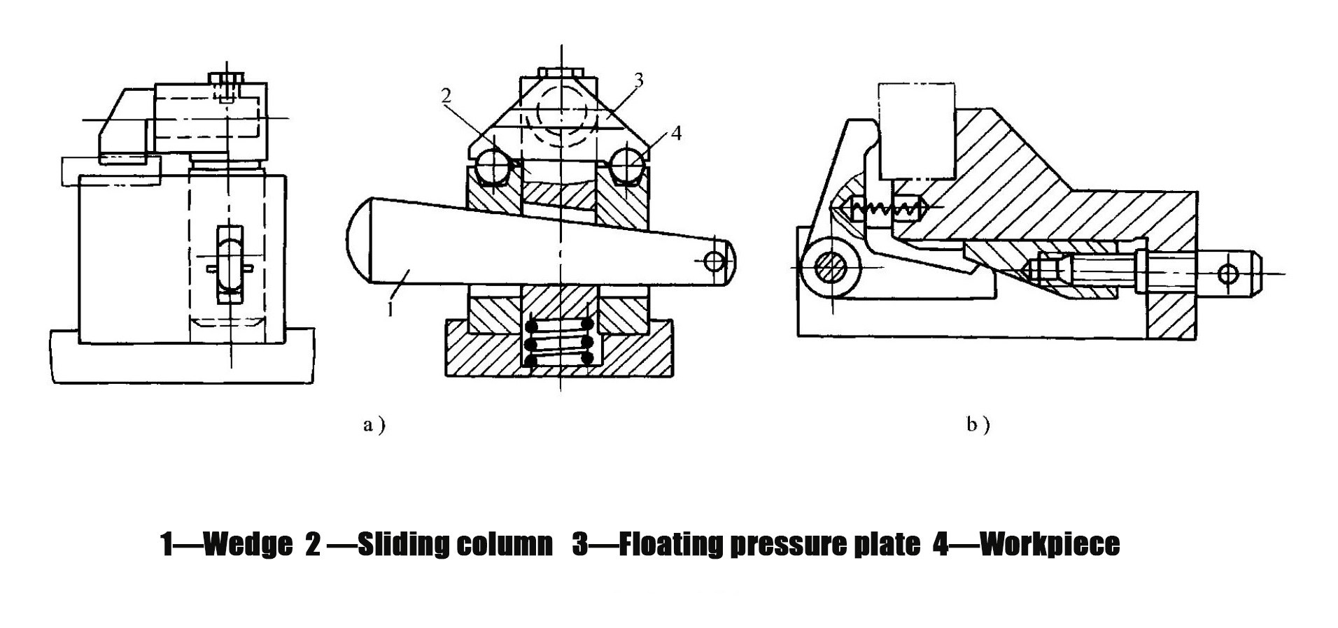
- Wedge clamping mechanism
- A clamping mechanism that uses a wedge as the force-transmitting or clamping element (Figure 1-52)
- Practical applications:
- In Figure 1-52a, driving wedge 1 downward forces sliding column 2 to move down, and the floating pressure plate 3 simultaneously clamps two workpieces 4; after machining, striking the small end of wedge 1 releases the workpieces
- In practical applications, wedge mechanisms are often combined with other mechanisms; Figure 1-52b shows a combination of a wedge and a screw clamping mechanism, where rotating the screw drives the wedge to move and causes the hinged pressure plate to clamp the workpiece
- Screw clamping mechanism
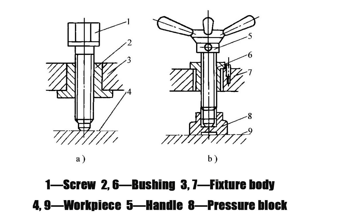
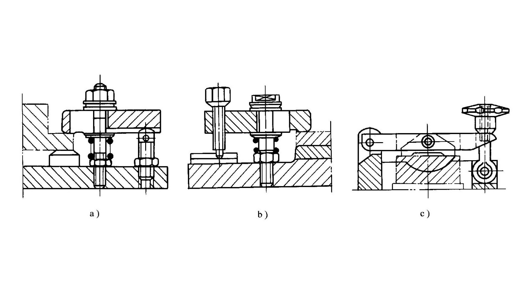
- A clamping mechanism composed of screws, nuts, washers, and pressure plates
- Features: Simple structure, easy manufacturing, good self-locking performance, and large clamping force, making it the most commonly used clamping mechanism in fixtures
- Practical applications:
- Figure 1-53 shows a single screw clamping mechanism; in Figure 1-53a, the screw directly presses the workpiece, which may damage the workpiece and cause rotation; Figure 1-53b overcomes this drawback by adding a pressure block under the screw head
- Figure 1-54 shows a typical screw pressure-plate clamping mechanism; Figures 1-54a and 1-54b are movable pressure-plate types that use the lever principle for clamping; due to different relative positions of the clamping point, fulcrum, and applied force point, the lever ratio and clamping force vary, with Figure 1-54c providing the highest force amplification
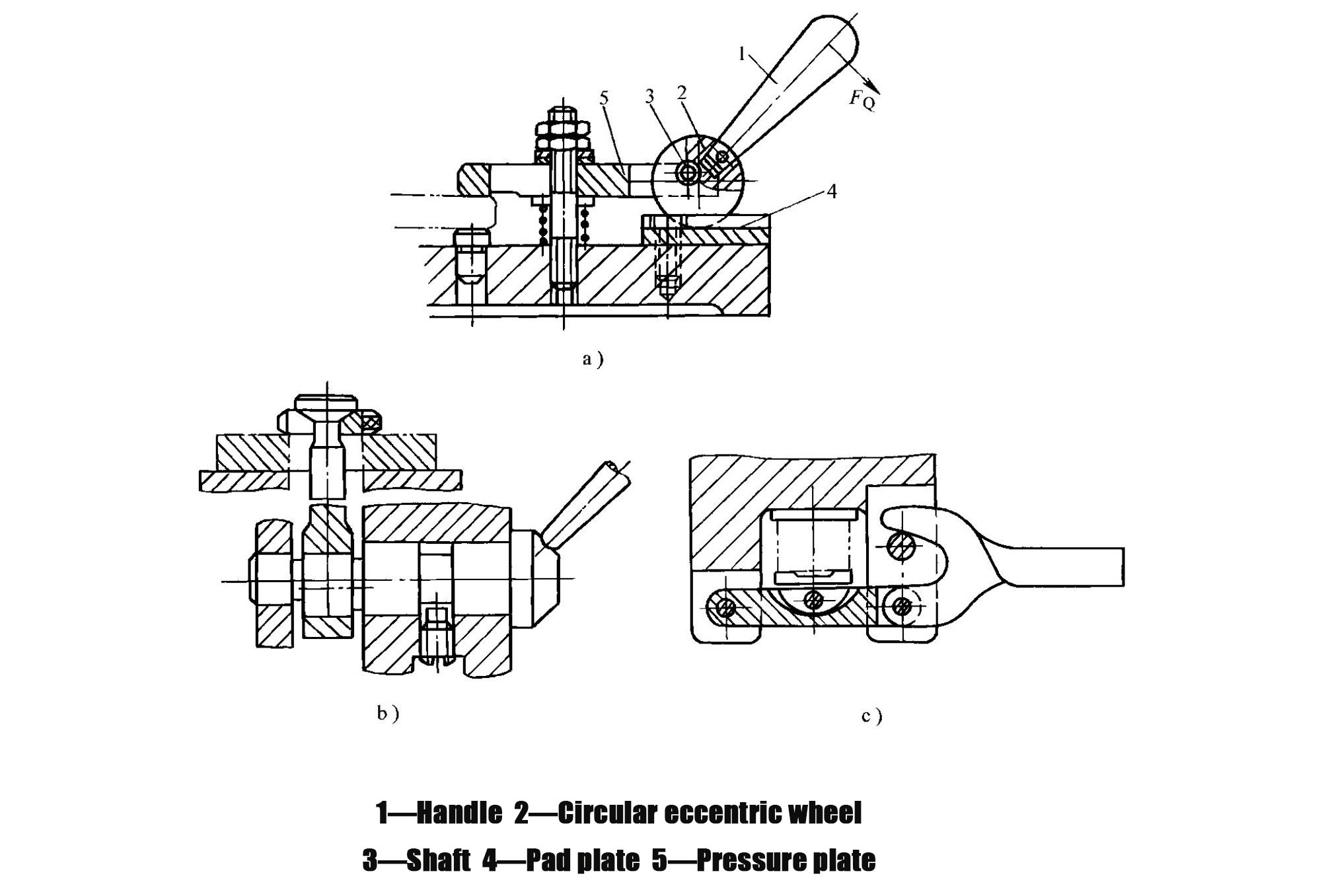
- Eccentric clamping mechanism
- A mechanism that clamps the workpiece directly or indirectly using an eccentric element (Figure 1-55)
- Practical applications:
- In Figure 1-55a, pressing handle 1 causes the circular eccentric cam 2 to rotate about shaft 3, pressing its cylindrical surface against backing plate 4; the reaction force lifts shaft 3 and drives pressure plate 5 to clamp the workpiece
- Figures 1-55b and 1-55c show mechanisms using an eccentric shaft and an eccentric fork, respectively
- Performance characteristics: Easy to operate and enables rapid clamping, but provides relatively small clamping force and stroke
- Application scope: Suitable for operations with low cutting forces, such as stamping small sheet-metal parts and quick positioning and clamping before drilling
7.5What Are the Characteristics of Common Pneumatic and Hydraulic Drive Systems?
Manual clamping relies on human force applied through force-transmission mechanisms to clamp the workpiece. In modern high-efficiency fixtures, powered clamping is widely used. Power systems include pneumatic, hydraulic, electric, electromagnetic, and vacuum drives, among which pneumatic and hydraulic transmission systems are the most commonly applied.
- Pneumatic Transmission Systems
- Working principle: Use compressed air as the power source
- Performance characteristics: Rapid actuation, adjustable pressure, low pollution, and simple equipment maintenance; however, they offer relatively low clamping rigidity and generally require larger structural dimensions
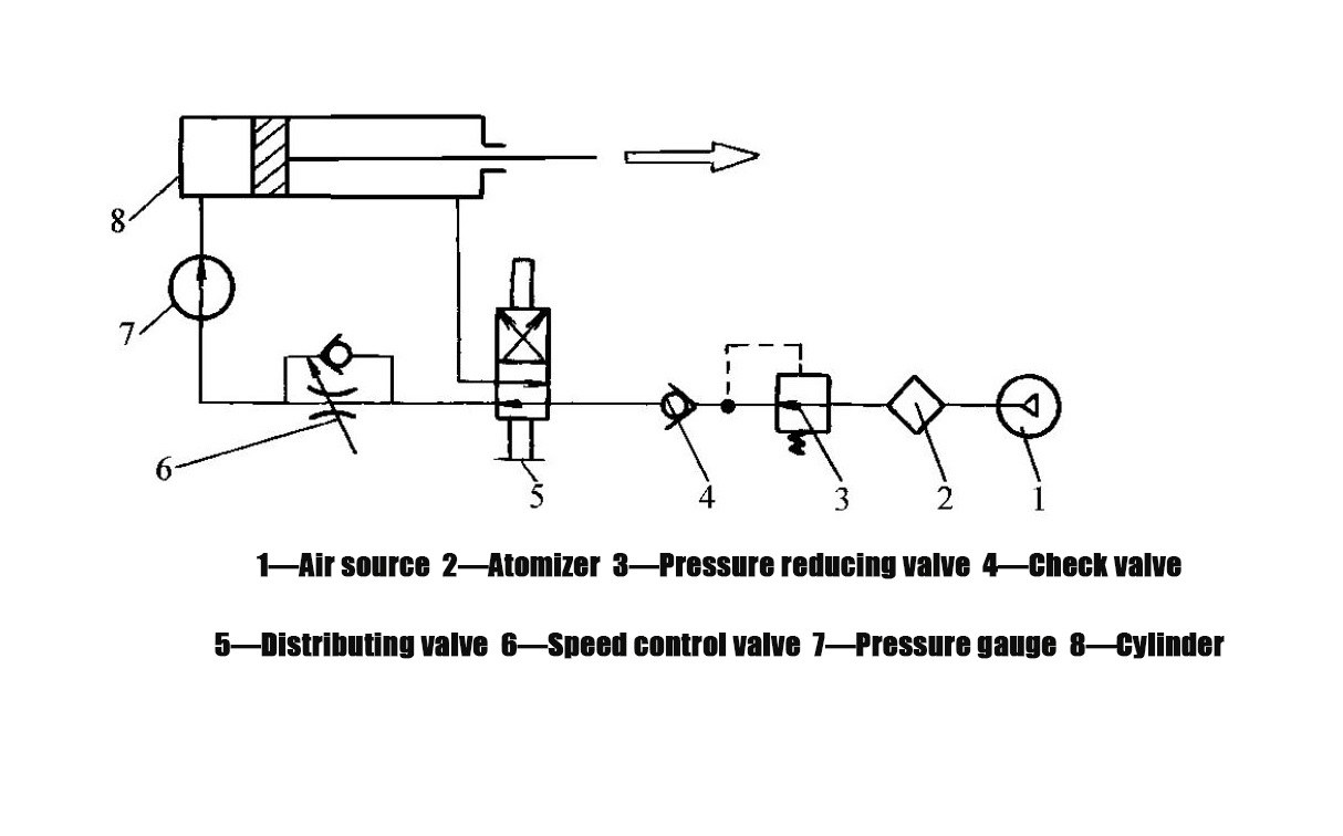
- Typical system composition (Figure 1-56): Compressed air supplied by the air source 1 passes through the lubricator 2 (where it mixes with atomized lubricating oil to lubricate the cylinder), the pressure-reducing valve 3 (which reduces the pressure to the working level), and the check valve 4 (which prevents loosening of the clamping mechanism in the event of air supply interruption or sudden pressure drop); the air is then controlled by the directional control valve 5 for air intake and exhaust, and the flow control valve 6 adjusts the piston movement speed; the pressure is indicated by pressure gauge 7; the cylinder 8 drives the piston, which in turn actuates the clamping mechanism to clamp the workpiece
- Commonly used pneumatic cylinders:
- Piston-type cylinders (Figure 1-57a): Provide a long working stroke, and the output force is not affected by stroke length
- Diaphragm-type cylinders (Figure 1-57b): Feature good sealing performance, a compact and simple structure, fewer friction components, and long service life; however, they have a short working stroke, and the output force varies with stroke length
- Application scope: Widely used in stamping press automation lines and for rapid clamping on machining centers
- Hydraulic Transmission Systems
- Working principle: Use pressurized oil as the working medium and operate on principles similar to pneumatic systems
- Performance characteristics compared with pneumatic systems: Offer larger clamping force, higher clamping rigidity, more reliable clamping, smaller cylinder size, and lower noise levels; main disadvantages are the tendency for oil leakage and the high manufacturing accuracy required for hydraulic components
- Practical application example (Figure 1-58): A bidirectional hydraulic clamping fixture for a milling machine; when pressurized oil enters chamber G of the working hydraulic cylinder 5 through pipeline A, the two pistons 4 are pushed outward simultaneously, driving pressure plates 3 to clamp the workpiece; when pressurized oil enters chambers E and F at both ends of the hydraulic cylinder 5 through pipeline B, the pistons 4 are pushed back; the springs 2 then force the pressure plates on both sides to return, releasing the workpiece
- Application scope: Especially suitable for machining operations requiring high clamping force, high rigidity, and stable positioning accuracy
8.0How to Select the Appropriate Machine Tool Fixture Based on Production Requirements
| Production Scenario | Recommended Fixture Type | Selection Reason |
| Single-piece & Small-batch Production | General-purpose fixtures, modular fixtures | Reduce cost, improve flexibility |
| Small-to-medium-batch Production | Adjustable fixtures | Adapt to multiple similar workpieces; balance efficiency and cost |
| Large-batch Production (Rotational Parts on Spinning Machines) | Dedicated self-centering fixtures | Optimize structure, simplify operation |
| Large-batch Production (Sheet Metal on Stamping Presses) | Special stamping fixtures | Match high-volume stable production requirements |
| New Product Trial Production | Modular fixtures | Quick reconfiguration, shorten trial cycle |
| Automated Production Lines | Transfer fixtures + pneumatic/hydraulic drive systems | Integrate clamping and workpiece transportation |
| High-precision Machining (Grinding) | Taper mandrel fixtures | Ensure high centering accuracy |
| High-precision Machining (Boring) | Interference-fit mandrels | Avoid over-positioni |
9.0Machine Tool Fixture Core FAQ (Frequently Asked Questions)
Q: What is a machine tool fixture?
A: A machine tool fixture is a process equipment used for workpiece setup in machining. It positions the workpiece accurately and then clamps it securely to ensure machining accuracy. Its core function is to achieve precise positioning and reliable clamping of the workpiece.
Q: What are the main classifications of machine tool fixtures?
A: By degree of specialization, fixtures can be classified as general-purpose, special-purpose, adjustable, modular, and transfer fixtures; by machine tool type, they include fixtures for lathes, milling machines, drilling machines, boring machines, and others; by power source, they can be manual, pneumatic, hydraulic, or electromagnetic fixtures.
Q: What is the core principle of workpiece positioning?
A: The core principle is the six-point positioning principle. A workpiece has six degrees of freedom in space (three translational and three rotational). By using six support points to restrict these six degrees of freedom, the workpiece position can be fully defined.
Q: What is the difference between complete positioning, incomplete positioning, over-positioning, and under-positioning?
A: Complete positioning restricts all six degrees of freedom; incomplete positioning restricts fewer than six degrees of freedom but still meets machining requirements, and both are commonly used; under-positioning fails to restrict required degrees of freedom and is strictly prohibited; over-positioning restricts the same degree of freedom multiple times and must be evaluated based on whether it affects accuracy.
Q: What are the basic requirements for clamping devices?
A: The clamping process must not alter the positioned workpiece location; the clamping force must be appropriate (stable without vibration or excessive deformation); operation should be convenient, labor-saving, and safe; and the level of automation should match the production volume.
Q: What are commonly used workpiece positioning elements?
A: For planar positioning: support pins, support plates, adjustable supports, and self-aligning supports; for external cylindrical surfaces: V-blocks, sleeves, and three-jaw self-centering chucks; for hole-based positioning: locating pins, cylindrical mandrels, taper pins, and taper mandrels; for one-plane–two-hole positioning: planar support combined with cylindrical pins and a relieved pin.
Q: How should an appropriate machine tool fixture be selected?
A: General-purpose or modular fixtures for single-piece and small batches; adjustable fixtures for small to medium batches; special-purpose or transfer fixtures for large batches; modular fixtures for new product trials; and high-centering-accuracy elements (such as taper mandrels) for high-precision machining, while avoiding over-positioning.
Q: How is clamping force estimated?
A: Two common methods are used: the analogy method, which estimates force based on similar fixtures and experience, and the static equilibrium method, which calculates theoretical clamping force and multiplies it by a safety factor (2.5–3 for rough machining, 1.5–2 for finish machining).
Reference
www.gressel.ch/en/wedge-clamping-element-kse/
eng.libretexts.org/Bookshelves/Mechanical_Engineering/Introduction_to_Aerospace_Structures_and_Materials_(Alderliesten)/03%3A_Analysis_of_Statically_Indeterminate_Structures/13%3A_Influence_Lines_for_Statically_Indeterminate_Structures/13.02%3A_Static_Equilibrium_Method