
- 1.0What Is Metal Cutting and Why Does It Matter in Manufacturing?
- 2.0How to Use Sawing in Metal Cutting: Types of Saws and Blades Explained
- 3.0What Is Shaping in Machining? How Shaping Machines Create Flat Surfaces
- 4.0What Is Broaching in Manufacturing? How Broaching Produces Complex Internal Shapes
- 5.0What Is Drilling, Reaming, Boring, and Tapping in Machining?
- 6.0What Is Grinding and Other Abrasive Machining Processes?
- 7.0What Is Turning in Machining? Understanding Lathe Operations and Work-Holding Methods
- 8.0What Is Milling in Machining? Types, Cutting Dynamics, and Tool Path Basics
- 9.0Work-Holding for Milling Operations: Fixtures, Clamps, and Setups
- 10.0Frequently Asked Questions (FAQ)
1.0What Is Metal Cutting and Why Does It Matter in Manufacturing?
Metal cutting is a machining process that removes material from a workpiece primarily through plastic deformation and shearing, forming small chips. This is a core operation in machining and is used to shape parts to precise dimensions.
Key Cutting Methods
Common cutting processes include:
- Sawing
- Shaping / Planing
- Broaching
- Drilling
- Grinding
- Turning
- Milling
Despite their differences in tools and machines, all of these processes rely on the same fundamental mechanism: applying cutting forces that induce plastic shearing to remove material, a mechanism often simplified using orthogonal cutting theory.
However, actual processes like milling or grinding involve oblique cutting with more complex mechanics. While orthogonal cutting theory provides basic insights, actual processes like milling and grinding involve oblique cutting and more complex mechanics.
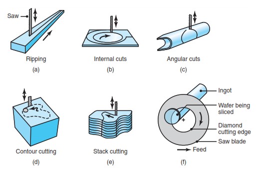
2.0How to Use Sawing in Metal Cutting: Types of Saws and Blades Explained
What Is Sawing in Metalworking?
Sawing is a fundamental machining process used to cut large raw material into smaller, workable pieces. This operation is often performed using bandsaw machines or integrated into CNC sawing systems for high-volume production. It is typically the first step in metal part manufacturing, providing rough cuts before precision machining.
Types of Saws Used in Metal Cutting
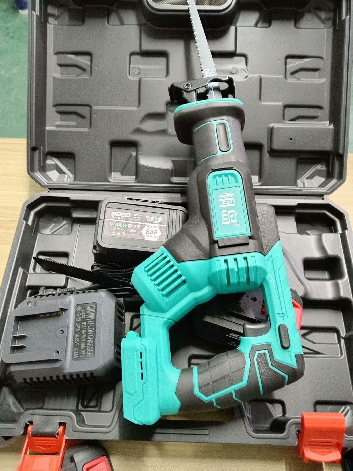
- Hacksaw
- Uses a straight blade in a reciprocating motion.
- Commonly operated manually or with simple power assistance.
- Ideal for cutting small sections or for workshop use.
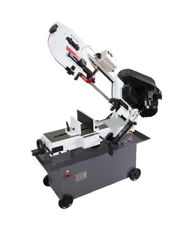
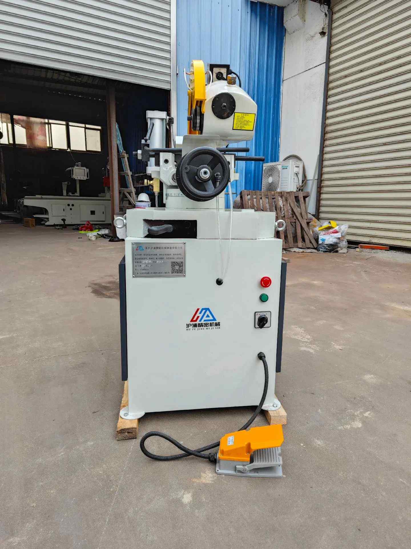
- Bandsaw
- Features a looped blade that moves continuously in one direction.
- Suitable for continuous, accurate cuts in various materials.
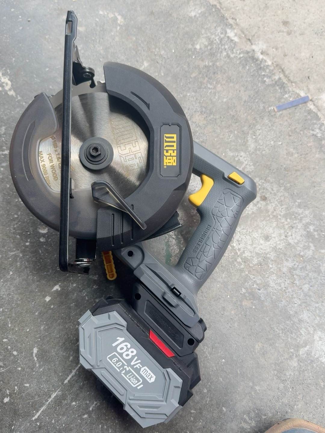
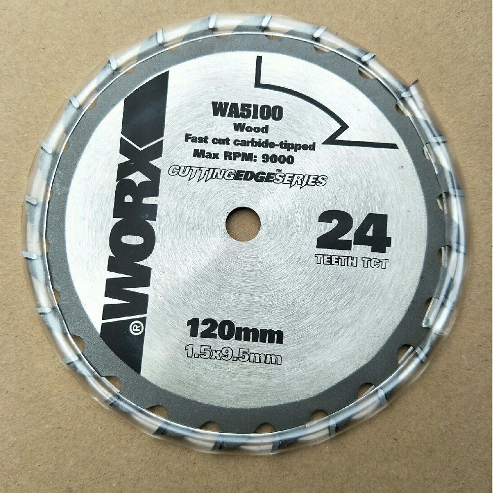
- Circular Saw
- Equipped with a rotating disc-shaped blade.
- Offers fast, clean cuts, often used in high-volume or portable operations.
Choosing the Right Saw Blade for the Material
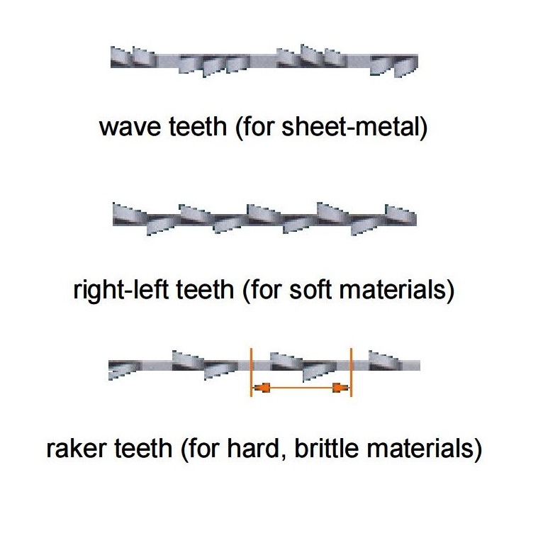
- Wave Teeth
- Best for thin sheet metals
- Blade teeth are wavy, reducing heat and improving chip evacuation.
- Right-Left Teeth (Set Teeth)
- Used for soft materials like aluminum or plastics.
- Teeth alternate directions to widen the cut and reduce binding.
- Raker Teeth
- Commonly used for hard materials, such as alloy steel, carbon steel, or cast iron..
- Teeth are grouped in patterns for smoother cutting and chip control.
Typical Sawing Applications
Sawing is typically used to:
- Rough cut stock materials to required length
- Prepare blanks for turning, milling, or drilling
- Remove excess material from cast or forged parts
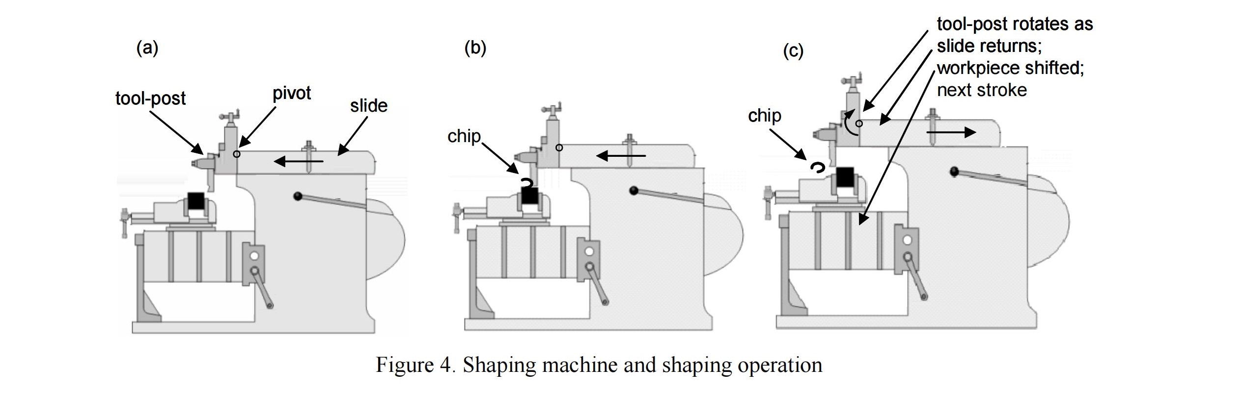
3.0What Is Shaping in Machining? How Shaping Machines Create Flat Surfaces
What Is Shaping in Machining? How It Creates Flat Surfaces
Shaping is a metal cutting process that uses a single-point cutting tool, typically operated on mechanical or hydraulic shaping machines, or sometimes on universal shaping lathes for toolroom work. It is primarily used to create flat or planar surfaces, especially on rectangular blocks of metal.
These flat surfaces often serve as the base geometry for further machining operations like milling or drilling.
How a Shaping Machine Works
- The cutting tool is mounted on a carriage and moves back and forth along a straight horizontal path.
- Only the forward stroke performs the cutting; the return stroke is idle.
- The workpiece remains stationary, typically clamped to the machine table.
- After each stroke, the table may feed the workpiece slightly for the next pass.
Applications of Shaping in Metalworking
- Producing flat surfaces on steel, cast iron, or aluminum blocks.
- Preparing workpieces for further machining (e.g., milling or grinding).
- Creating keyways, grooves, or internal slots with special tooling.
- Suitable for low- to medium-volume production and repair work.
Advantages of Shaping
- Simple machine design and operation.
- Cost-effective for small batch jobs or toolroom work.
- Can produce accurate flat surfaces with proper setup.
4.0What Is Broaching in Manufacturing? How Broaching Produces Complex Internal Shapes
Broaching is a high-precision, high-efficiency machining process used primarily for mass production of parts with complex internal geometries, especially non-circular holes, splines, or keyways.
How Broaching Works
- A broach tool consists of a long bar with a series of cutting teeth arranged progressively along its length.
- As the broach is pulled or pushed through the workpiece, each tooth removes a small chip of material.
- The initial teeth perform rough cutting, removing the majority of the material.
- The final teeth provide finishing cuts, defining the exact final geometry with high precision and surface quality.
- The shape of the last teeth matches the desired final internal shape of the part.

Applications of Broaching
- Machining keyways, internal splines, non-round holes, and slots
- Common in industries such as automotive, aerospace, and tooling
- Suitable for high-volume production where tight tolerances are required
Advantages of Broaching
- Produces complex internal shapes in a single pass
- Offers excellent surface finish and dimensional accuracy
- High repeatability and cycle time efficiency for mass production
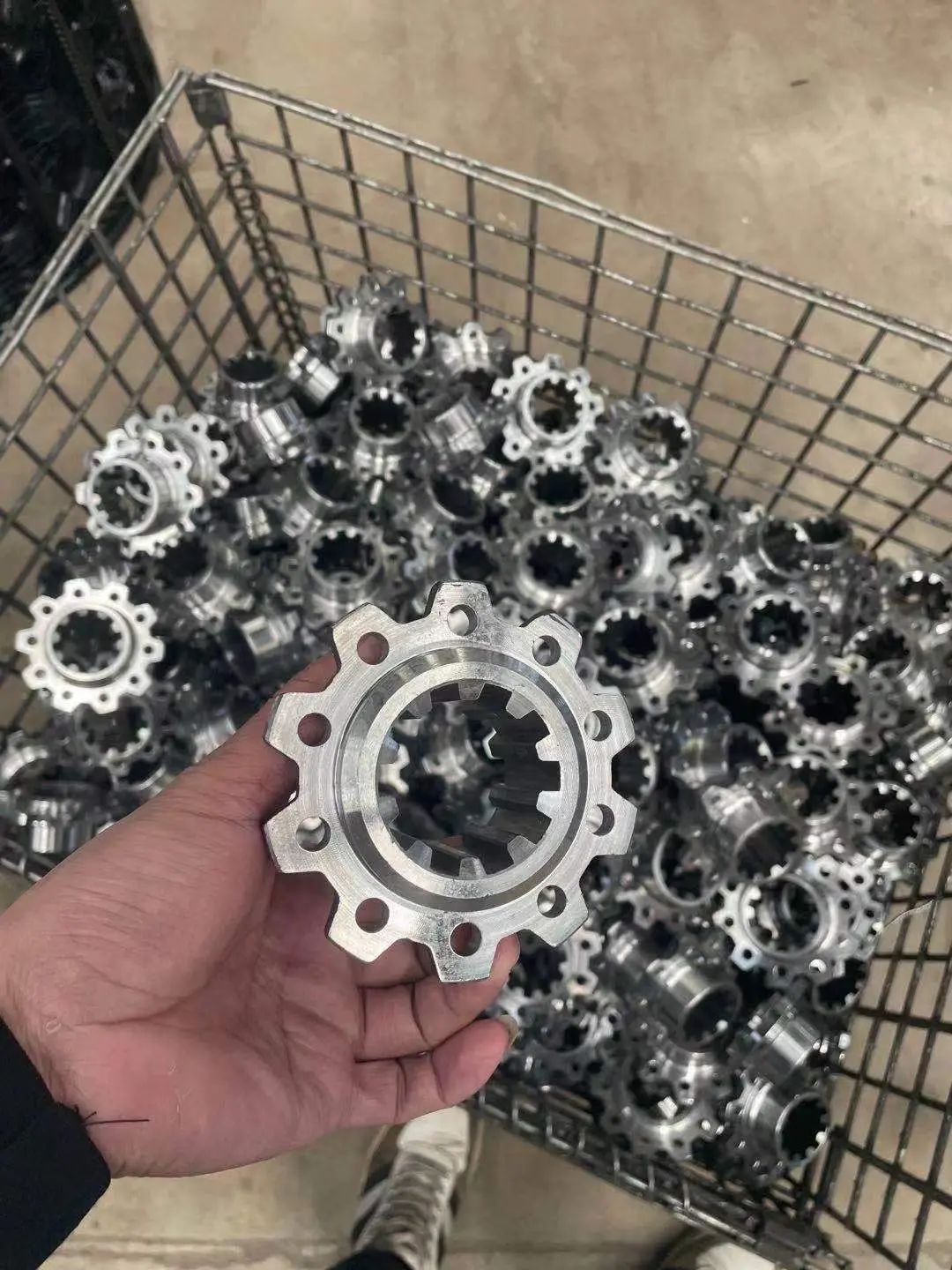
5.0What Is Drilling, Reaming, Boring, and Tapping in Machining?
Overview of Drilling, Reaming, Boring, and Tapping Processes
These four machining methods are used to produce holes of different types. They are commonly performed using drill presses, radial drilling machines, or CNC machining centers, depending on precision requirements, Drilling produces round holes of various types; reaming is used to improve the dimensional tolerance of a drilled hole; boring uses a special machine operating like a lathe to cut high-precision holes; and tapping creates screw-threads in drilled holes.
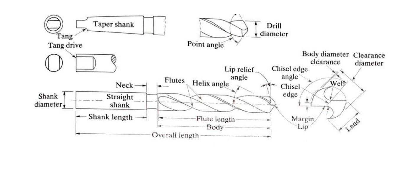
How Drilling Works: Twist Drill Geometry and Cutting Process
The geometry of the common twist drill tool (called a drill bit) is complex. It has straight cutting teeth at the bottom—these teeth do most of the metal cutting—and curved cutting teeth along its cylindrical surface. The grooves created by the helical teeth are called flutes, which are useful for pushing chips out from the hole as it is being machined.
The velocity at the tip of the drill is zero, so this region of the tool does not perform significant cutting. Therefore, it is common to machine a small hole, called a center-hole, before drilling. Center-holes are made by special tools called center-drills, which also help align the drill bit with the center of the hole.
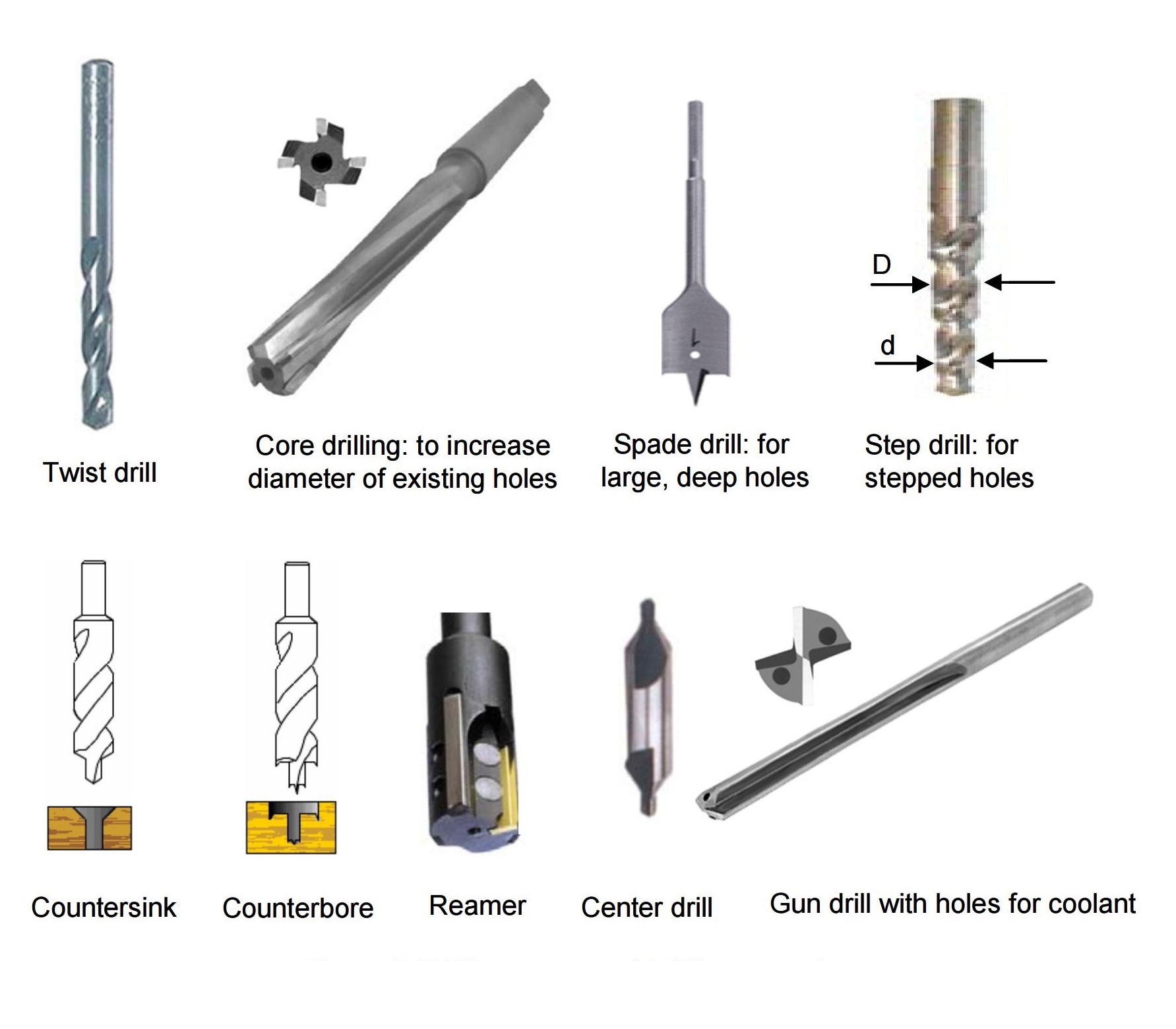
Key Facts About Drilling Tools and Operations
- Common Drill Bit Materials: Hardened steel (High Speed Steel, Titanium Nitride-coated steel); for harder materials, drills with carbide or CBN inserts are used.
- Point Angle Selection: Drills for cutting softer materials have smaller point angles, while those for hard and brittle materials have larger point angles.
- Gun-Drilling for Deep Holes: When the Length/Diameter ratio of a hole is large, special guiding support and long drills are required. Gun-drilling is used for holes with diameters of a few millimeters or more and L/D ratios up to 300, such as gun barrels.
- Limitations for Small Holes: Drilling is not suitable for holes smaller than 0.5 mm, as tools may break and get stuck.
- Hole Size Accuracy: Drilled holes are usually slightly larger than the drill’s measured diameter due to vibration, misalignment, and other factors.
- Reaming for Tight Tolerances: For precise hole diameters, a slightly smaller hole is drilled first, then reamed. Reaming removes little material but provides excellent dimensional accuracy.
- Spade Drills for Large and Deep Holes: Used to machine large-diameter or deep holes.
- Countersink and Counterbore Drills: These have multiple diameters to make chamfered or stepped holes for screws or bolts; the larger diameter accommodates the screw or bolt head.
- Tapping Internal Threads: Internal threads are cut into drilled holes using tapping tools.
Reaming Process: Improving Dimensional Tolerance
Reaming is used after drilling to improve dimensional tolerance and surface finish. It has a low material removal rate and low depth of cut but provides excellent accuracy.
Boring Process: Cutting High-Precision Holes
Boring uses a special machine operating like a lathe to enlarge and finish holes to high precision. It is suitable for applications requiring tight tolerances and smooth surfaces.
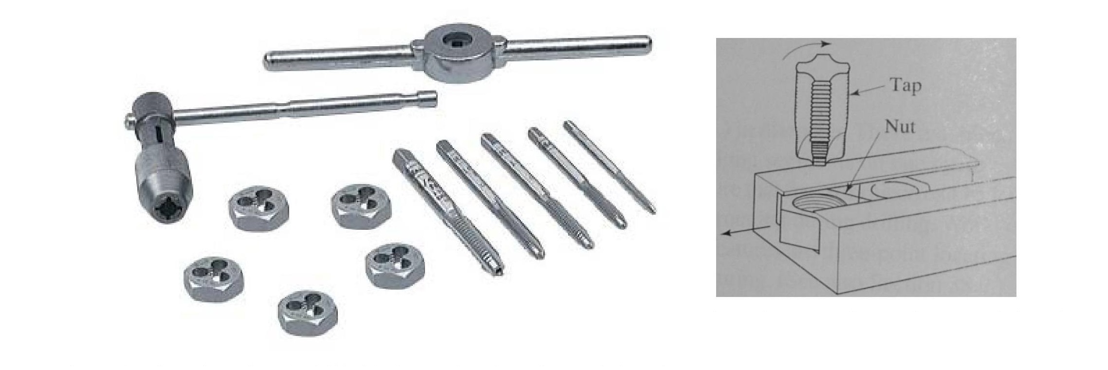
Tapping Process: Creating Internal Screw-Threads
Tapping creates internal screw-threads in drilled holes. A tapping tool is used for internal threads, while external threads on cylindrical parts are cut using a tapping die.
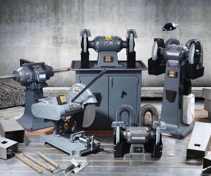
6.0What Is Grinding and Other Abrasive Machining Processes?
Overview of Grinding and Abrasive Machining
Abrasive machining uses tools made of tiny, hard particles of crystalline materials. Abrasive particles have irregular shapes and sharp edges, removing very small amounts of material at random contact points. Using a large number of particles averages the cutting effect across the surface, producing excellent surface finish and dimensional control, even for hard or brittle workpieces.
Grinding is also widely used for machining brittle materials using various grinders, such as surface grinders, cylindrical grinders, or CNC grinding machines, which cannot be easily processed by conventional cutting methods due to random fractures and cracking.
Main Applications of Grinding and Abrasive Machining
1. Improving Surface Finish of Parts Made by Other Processes
- Example (a): A steel injection molding die is first machined by milling; its surface finish is improved for better plastic flow, either by manual grinding with shaped grinding tools or by electro-grinding.
- Example (b): The internal surfaces of car engine cylinders are turned on a lathe, then ground, followed by honing and lapping to achieve a mirror-like finish.
- Example (c): Sandpaper is used to smooth rough-cut wood surfaces.
2. Improving Dimensional Tolerance of Parts
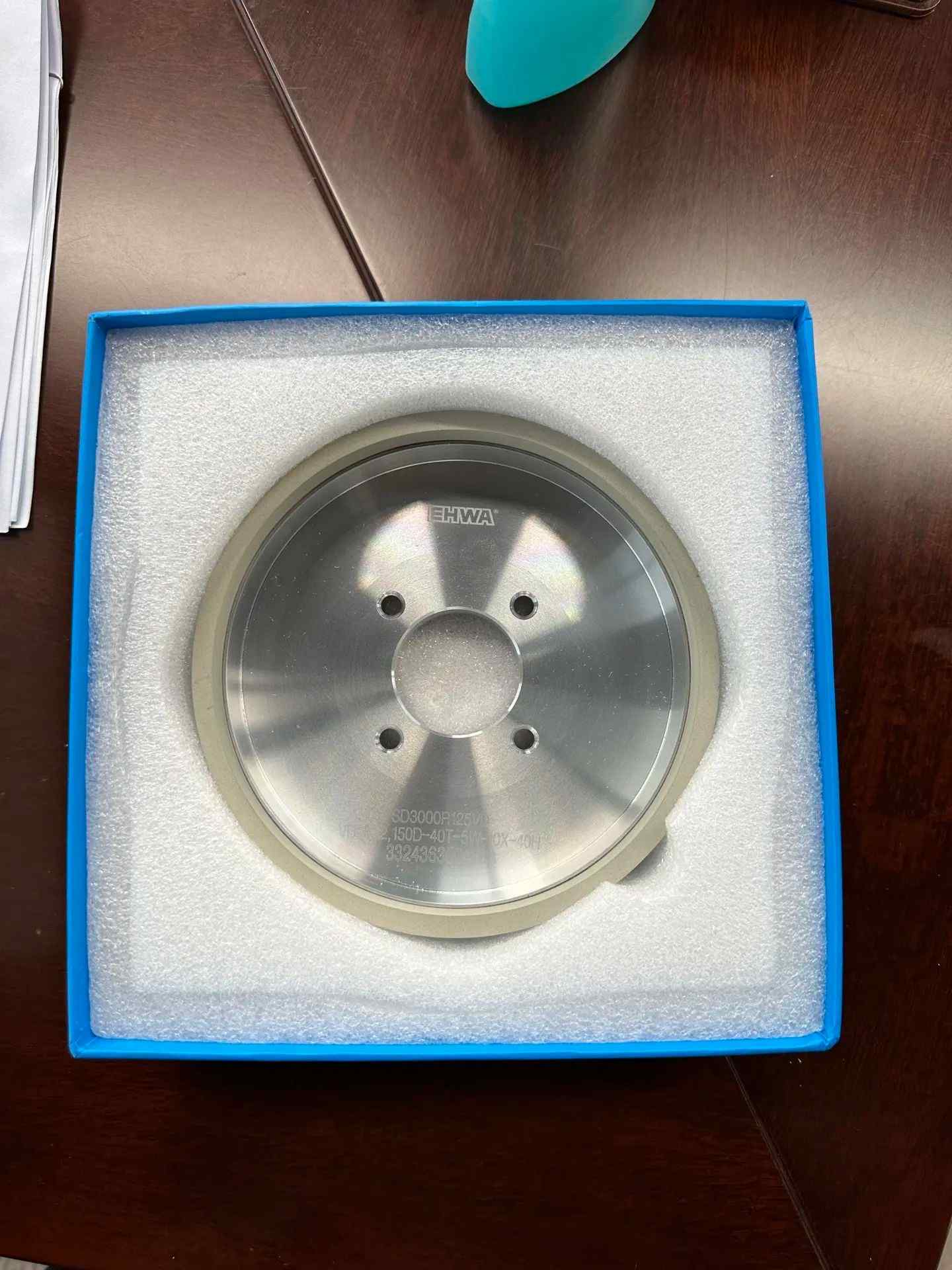
- Example (a): Ball bearings are forged into initial round shapes, then ground in specially formed grinding dies to achieve extremely accurate diameters (≤15 μm).
- Example (b): Knives are made from forged steel, hardened, and finally ground to achieve a sharp cutting edge.
3. Cutting Hard and Brittle Materials
Example (a): Semiconductor IC chips are made from silicon. A long silicon crystal rod (8 cm, 15 cm, or 30 cm diameter; up to 200 cm length) is sliced into thin wafers using a diamond abrasive wheel.
4. Removing Unwanted Material from Cutting Processes
Example (a): Drilling and milling often leave small sharp chips, called burrs, along surface edges. Tapered grinding wheels are used for deburring.
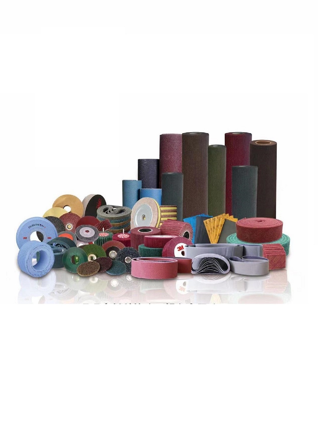
Common Abrasive Materials
- Aluminum Oxide and Silicon Carbide: Common abrasives for general applications.
- Superabrasives (CBN and Diamond Powder): Used for harder materials and high-precision applications.
- Key Properties: High hardness and high friability. Friability refers to the brittleness of abrasive particles, causing them to fracture and form new sharp edges during use.
Abrasive Tools and Bonding Materials
Abrasive tools contain abrasive grains bonded by resin, hardened rubber, metal, or ceramic. The bonding material must be softer than the abrasive to allow worn abrasive grains to release, continuously exposing fresh cutting edges.
Grain Size and Surface Finish:
Coarse grains (small grain size number, e.g., 10) provide high material removal rates.
Fine grains (large grain size number, e.g., 100) produce better surface finishes.
This grain size classification is evident in sandpaper grades.
Types of Grinding Machines and Operations
- Surface Grinders: Produce flat surfaces. The workpiece is held on a flat table, often by magnetic chucking for steel parts, and reciprocated along the X-axis while the grinding wheel lowers along the Z-axis.
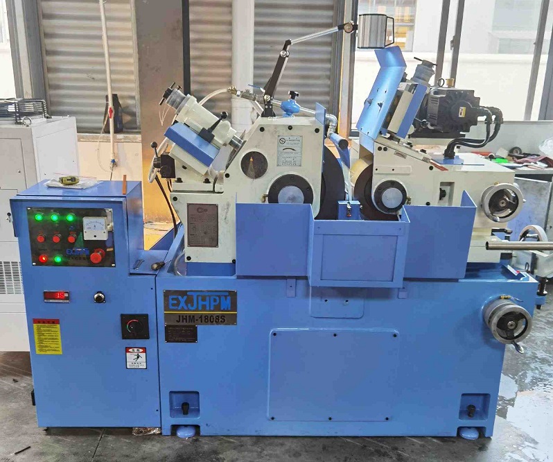
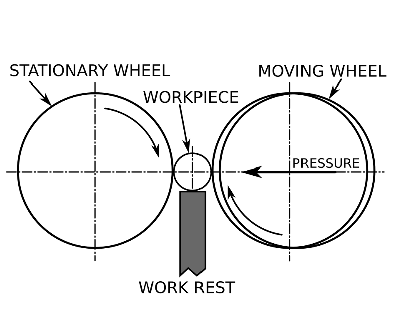
- Centerless Grinders: Used for cylindrical parts requiring tight dimensional control. The misaligned axes of the regulating wheel and grinding wheel move the part axially for controlled grinding time.
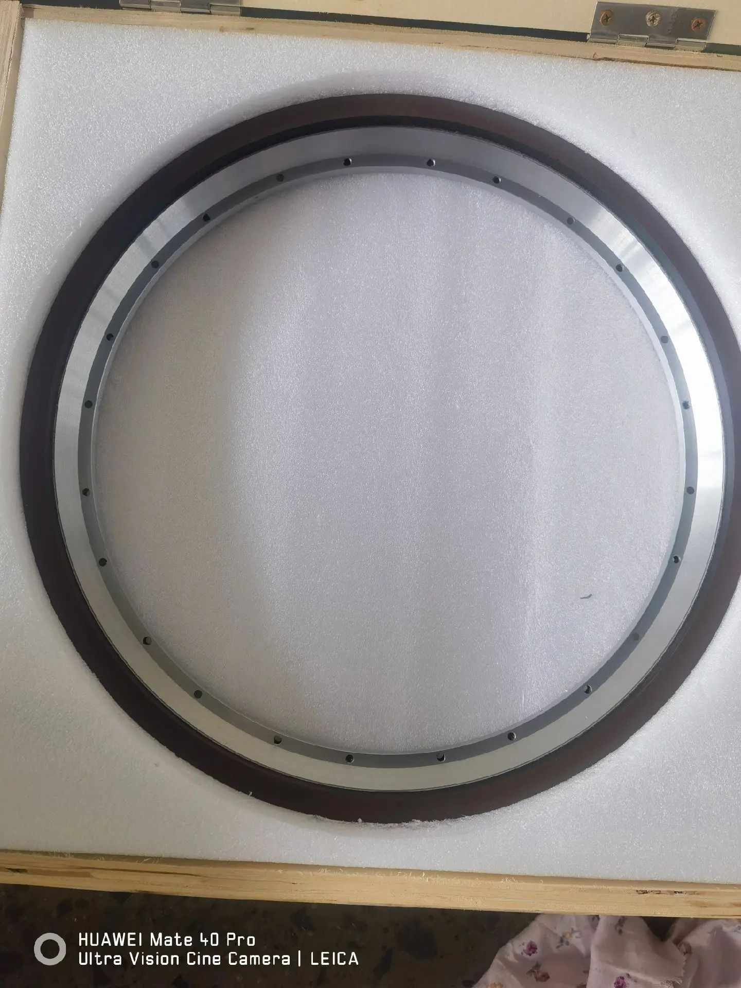
- Cylindrical Grinders: Used for turned parts with complex shapes (e.g., stepped shafts). Specially profiled grinding wheels match the workpiece profile.
What Is Honing in Machining? Improving Cylindricity of Cylindrical Parts
Honing improves the form tolerance, particularly the cylindricity, of cylindrical surfaces. The honing tool consists of a metal bar with grinding stones arranged in a circular pattern, brushing along the surface while rotating and moving axially. Honed surfaces show characteristic helical cross-hatched scratch marks.
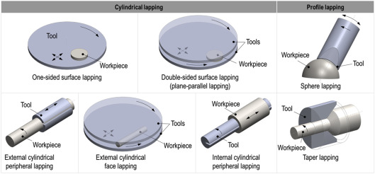
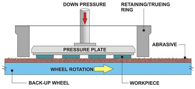
Lapping Process for Ultra-Fine Surface Finishing
Lapping is a finishing process using a metal, leather, or cloth tool impregnated with very fine abrasive particles. For silicon wafer preparation, a flat metal disc rotates slightly above the part with a slurry containing fine abrasive grains. The slurry movement produces ultra-fine finishes, achieving dimensional tolerances of ≥0.5 μm and surface finishes up to 0.1 μm.
7.0What Is Turning in Machining? Understanding Lathe Operations and Work-Holding Methods
Overview of Turning Process
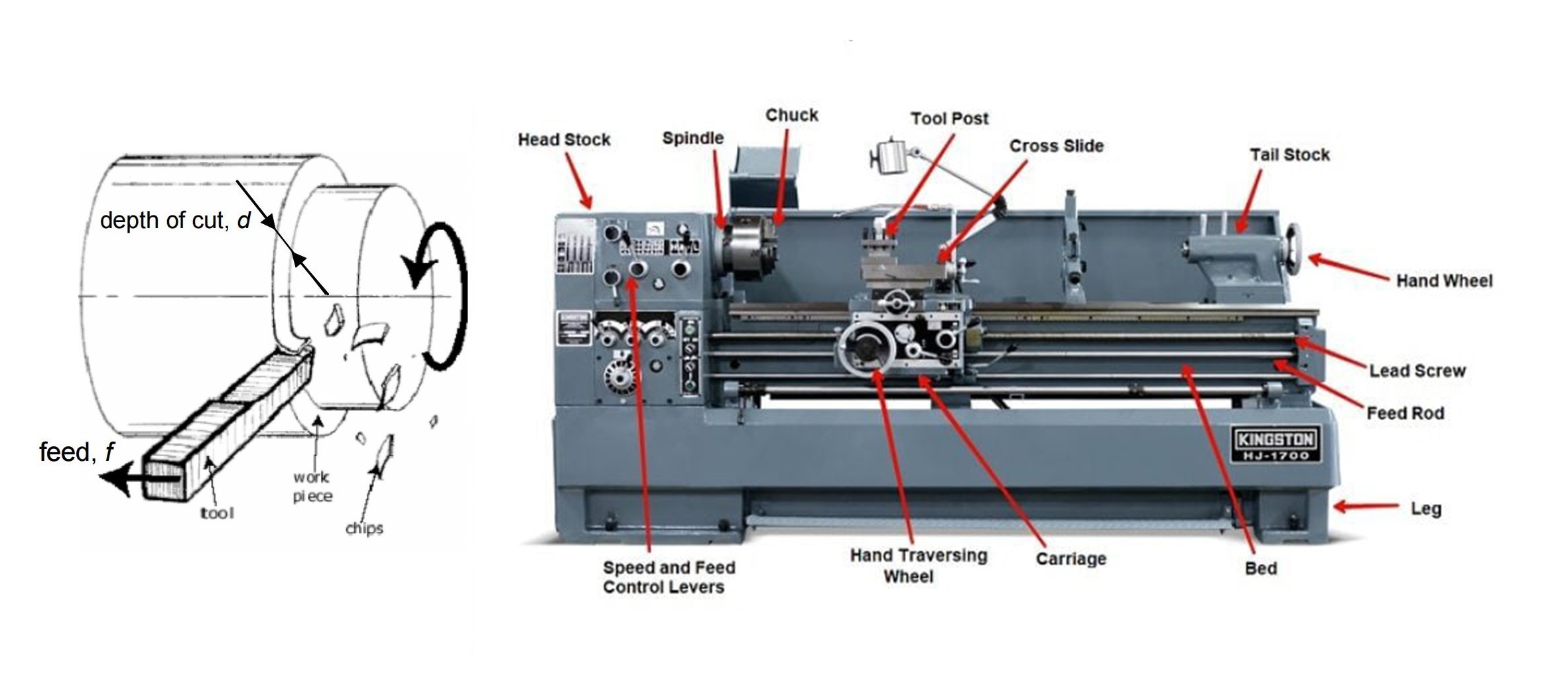
Turning is a machining process where the workpiece rotates against a stationary cutting tool mounted on a lathe, removing material to form rotational shapes, where the workpiece is rotated while a cutting tool is fed against it. Typically, the raw material is cylindrical, and the machined parts are rotationally symmetrical, meaning all lathe-cut surfaces are surfaces of revolution.
There are two common ways to use a lathe:
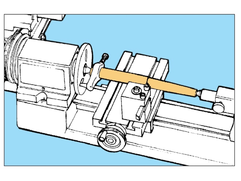
- Drilling with Tailstock: A drill mounted in the tailstock feeds into the end face of the rotating part to cut holes. The cylindrical part is held in a chuck, rotated at high speed, and the tailstock wheel feeds the tool into the part.
- Turning with a Single-Point Cutting Tool: A single-point tool held in the tool post cuts the rotating part. The tool post moves along the slide using the carriage wheel, while the cross-slide wheel moves the tool closer or farther from the rotation axis, controlling depth of cut and feed rate.
Typical Lathe Cutting Operations
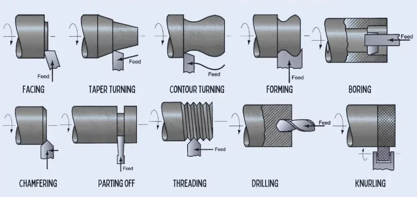
Turning can produce a variety of revolved shapes by cutting different surfaces:
- Outer Cylindrical Surfaces: Turning, taper cutting, groove cutting, cut-off, thread cutting, knurling
- Planar End Faces: Facing, face groove cutting, drilling
- Inner Cylindrical Surfaces: Boring, internal groove cutting (accessed through a free planar face)
Only drilling requires the tool to be fed by moving the tailstock along the slide. In other operations, the bar stock is held in a spindle fixture, with the opposite face free. For long stock, the tailstock may provide extra support using a dead-center.
Planning Machining Sequences on a Lathe
When multiple operations are performed on one workpiece, the sequence must be carefully planned to minimize re-fixturing. For instance, if both planar ends need facing, at least two setups with a chuck are required.
Common Work-Holding Methods for Lathes
The stock is typically held at the spindle side using one of the following:
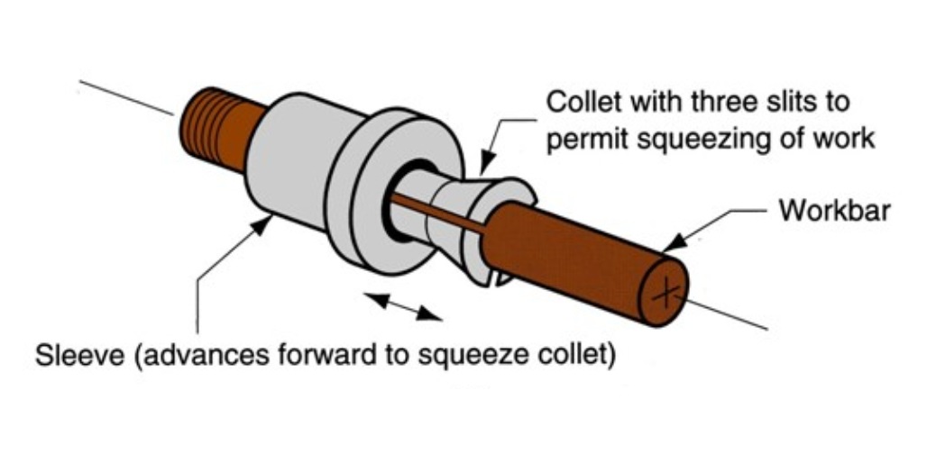
- Collets: Common in automatic feeding lathes. A long bar is progressively machined and cut off; the collet releases and re-grips the bar for the next part.
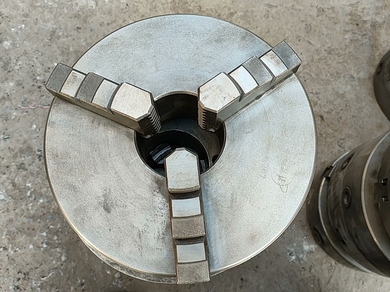
- 3-Jaw Chucks: All three jaws move simultaneously, keeping the bar axis aligned with the spindle. Three positions are possible:
- Gripping the outer cylindrical surface (standard method).
- Gripping internal cylindrical surfaces (e.g., tubes) from inside, using outward force.
- Holding larger bars by reversing the jaws to grip different step levels.
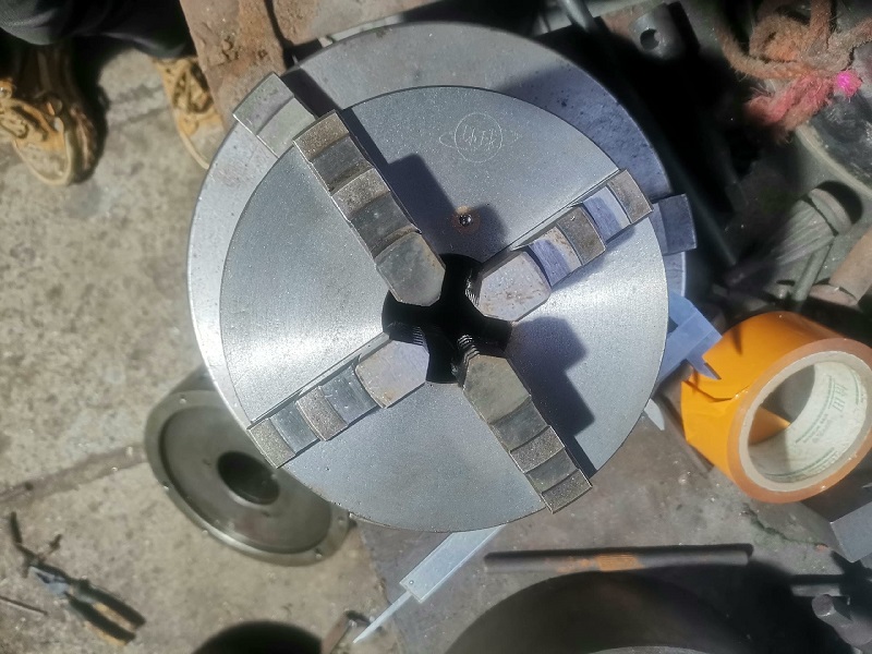
- 4-Jaw Chucks: Allow machining of rotational parts whose axis is offset but parallel to the part axis, as opposite jaw pairs move independently.
- Dead-Center and Live-Center Support: Long parts can be held between a live center at the spindle and a dead center at the tailstock for stability.
8.0What Is Milling in Machining? Types, Cutting Dynamics, and Tool Path Basics
Overview of Milling Process
Milling is one of the most versatile machining processes, capable of producing a wide variety of shapes. A large percentage of molds and dies used in manufacturing are produced by milling.
The most common milling operations are:
- Slab Milling
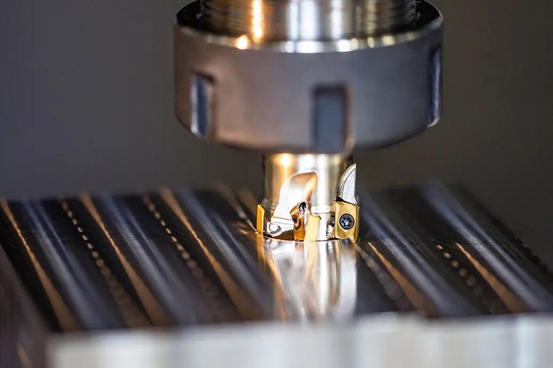
- Face Milling
- End Milling
These operations are distinguished primarily by the different cutting tools used.
End Milling Operations and Tool Types
End milling uses specialized tools to produce complex geometries, including curved surfaces and slots.
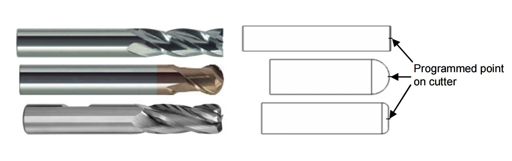
- Flat End Mill: Used for cutting flat or slightly curved surfaces.
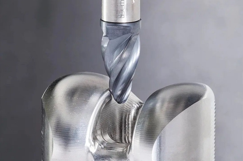
- Ball End Mill: Provides smooth surface finishing, commonly used for molds.
- Formed End Mill (T-Slot Cutter): Designed for cutting T-slots and other specific profiles.

How Milling Works: Cutter Path and Tool Motion
Most milling cutters have multiple teeth (from 2 to ~20 flutes), each forming a helix around the cylindrical tool body. The orientation of the cutting edge determines the tool rotation direction and spindle motion.
Workpiece and Cutter Motion: The workpiece is clamped on the machine table, which moves along X, Y, and Z axes—often simultaneously—to create the programmed “cutter path.” Although the part moves while the cutter remains fixed in space, this motion is conventionally referred to as cutter movement.
Up Milling vs Down Milling: Cutting Dynamics
The interaction between the tool and workpiece changes depending on relative motion:
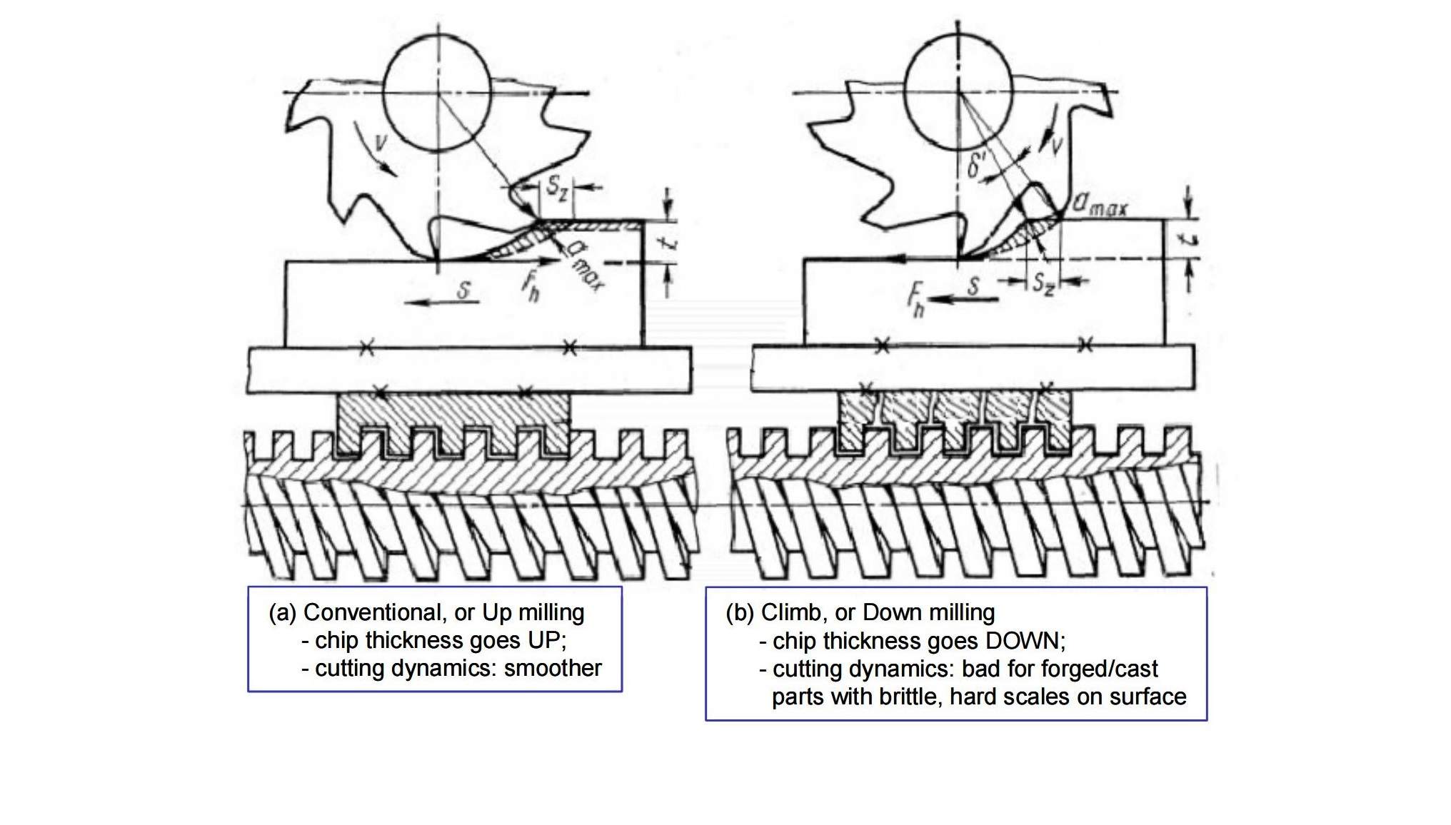
Conventional (Up) Milling
- The tooth engages with zero chip thickness initially, and chip thickness increases gradually to maximum at disengagement.
- Useful for cutting forged or cast parts with hard surface oxides (scales), reducing initial cutting forces.
- However, initial sliding causes high friction, tool flank wear, and strain hardening due to plastic deformation before cutting begins.
Down Milling
- The tooth engages the workpiece at maximum chip thickness and gradually reduces cutting forces as it exits.
- Produces better surface finish and slightly longer tool life compared to up milling.
- Preferred for most modern milling operations, though optimized tool paths may mix both up and down milling.
9.0Work-Holding for Milling Operations: Fixtures, Clamps, and Setups
Common Work-Holding Methods in Milling
Several types of fixtures are commonly used to hold parts securely during milling operations:
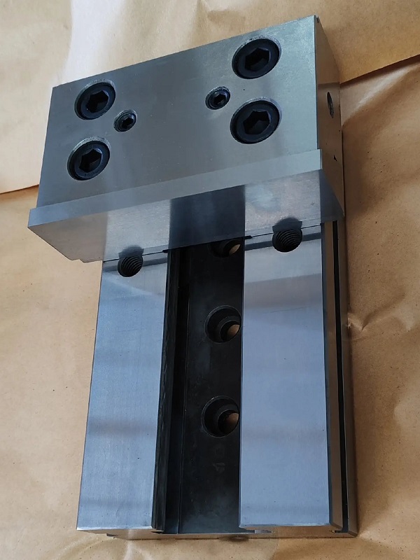
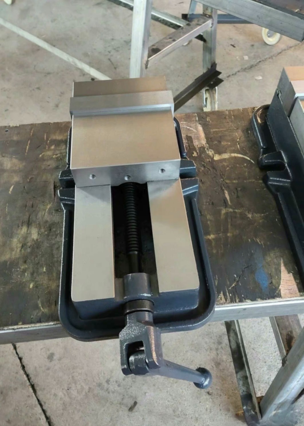
- Vise: The most common fixture for general milling applications.
- Direct Clamping on Machine Table: Parts can be clamped directly to the machine table using T-slots along the table length to position and secure the clamps.
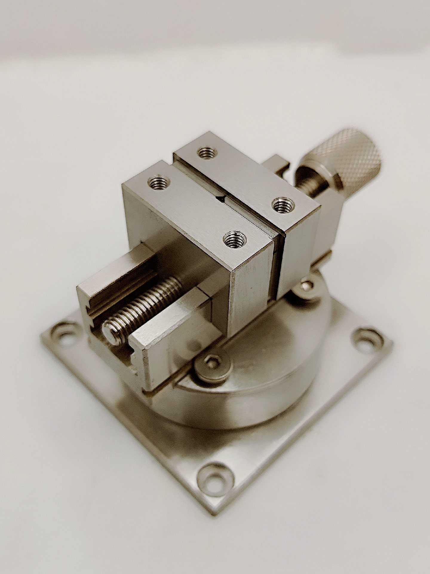
- Indexed Vise: Allows quick rotation of the part to expose different surfaces to the milling tool, improving efficiency when machining multiple facets.
Understanding Setups in Milling Operations
If the milling tool needs to access different surfaces or facets of a part, the part may need to be released and re-fixtured. Each fixed position is called a setup.
- Multiple Tools per Setup: In one setup, multiple cutting tools can be used to machine different features.
- Part Location and Machine Coordinates: Whenever the setup or tool changes, the machinist must locate the part—determining the part’s coordinates relative to the tool.
- Machine Table Feedback: Milling machine tables provide feedback about relative motion along the X, Y, and Z axes. Correctly locating the part ensures precise movement of the machine table, which is essential for achieving accurate feature dimensions.
10.0Frequently Asked Questions (FAQ)
1. What is metal cutting and why is it important in manufacturing?
Metal cutting is the process of removing material from a workpiece using cutting forces that cause plastic deformation and shearing. It’s essential in manufacturing for shaping parts with precise dimensions and surface finishes.
2. What are the main types of metal cutting processes?
The key methods include:
- Sawing
- Shaping / Planing
- Broaching
- Drilling
- Grinding
- Turning
- Milling
3. How does sawing work in metal cutting?
Sawing is used to roughly cut raw materials into smaller, manageable sizes. It’s often the first step before more precise machining.
Types of saws:
- Hacksaw: Manual or powered, straight reciprocating blade.
- Bandsaw: Continuous looped blade, good for steady cuts.
- Circular saw: Fast, rotating disc-shaped blade for clean cuts.
Blade types:
- Wave teeth: For thin sheet metals.
- Right-left teeth: For soft materials like aluminum or plastic.
- Raker teeth: For hard materials like carbon or alloy steel.
4. What is shaping in machining?
Shaping creates flat surfaces using a single-point cutting tool in a reciprocating motion. It’s good for producing planar surfaces on rectangular blocks.
5. What is broaching and when is it used?
Broaching is a high-precision method used for creating complex internal shapes like keyways, splines, or non-circular holes. It’s ideal for mass production requiring tight tolerances.
6. What are the differences between drilling, reaming, boring, and tapping?
| Process | Purpose |
| Drilling | Creates initial round holes. |
| Reaming | Improves hole diameter accuracy. |
| Boring | Enlarges holes to high precision. |
| Tapping | Cuts internal threads in drilled holes. |
7. What tools are used in drilling operations?
- Twist drill: Most common, with flutes for chip removal.
- Center drill: Starts the hole and ensures alignment.
- Gun drill: For deep, high aspect-ratio holes.
- Spade drill: For large-diameter or deep holes.
- Countersink / Counterbore: For stepped or chamfered holes.
- Taps: For internal threading.
8. What is grinding and when is it used?
Grinding is an abrasive machining process used for:
- Achieving high surface finish
- Improving dimensional accuracy
- Cutting hard/brittle materials
- Removing burrs and surface defects
It uses tools with bonded abrasive grains like aluminum oxide or diamond.
References
https://www.uniquespm.com/broaching-machines.html
https://lnf-wiki.eecs.umich.edu/wiki/Lapping
https://www.sciencedirect.com/topics/engineering/lapping-plate