- 1.0Blanking Operation
- 2.0Pull-Down
- 3.0Breakage
- 4.0Blank Design – Minimum Blank Sections
- 5.0Corners
- 6.0Notches
- 7.0Specifying Cutoffs
- 8.0Specifying Holes – Minimum Diameters
- 9.0Hole Tolerance
- 10.0Holes and Openings Near Blank Edge
- 11.0Notches as Hole Substitutes
- 12.0Holes and Openings Near Bends
- 13.0Minimum Requirements for Hole Location
- 14.0Specifying Internal Tabs
- 15.0Specifying Bends
- 16.0Bending – Bulging, Fracture, and Burr Side Considerations
- 17.0Specifying Countersinking
- 18.0Spot Weld Tips
- 19.0Dimensioning
- 20.0Extrusions
- 21.0Embossed Stampings
- 22.0Burr Removal
- 23.0Flatness
- 24.0Surface Finish on Stamped Parts
- 25.0Turret Press Dimensioning
- 26.0Press Brake Dimensioning Best Practices
- 27.0Laser Cutting Combined with Turret Punching
- 28.0Designing Parts for Laser Processing
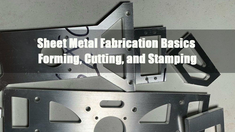
Designing sheet metal parts for stamping and laser cutting requires more than just CAD accuracy—it demands a deep understanding of manufacturing tolerances, material behavior, and cost-effective design practices. From blanking and bending to laser edge quality and minimum hole sizes, each design decision directly impacts part performance, manufacturability, and total production cost.
1.0Blanking Operation
Blanking involves cutting parts using a punch and die set that matches the part’s outer contour. A clearance is required between the punch and die.
This clearance causes the punch to cut through part of the material and then fracture the remainder.
Before cutting begins, the punch deforms the material surface slightly — this deformation is known as pull-down.
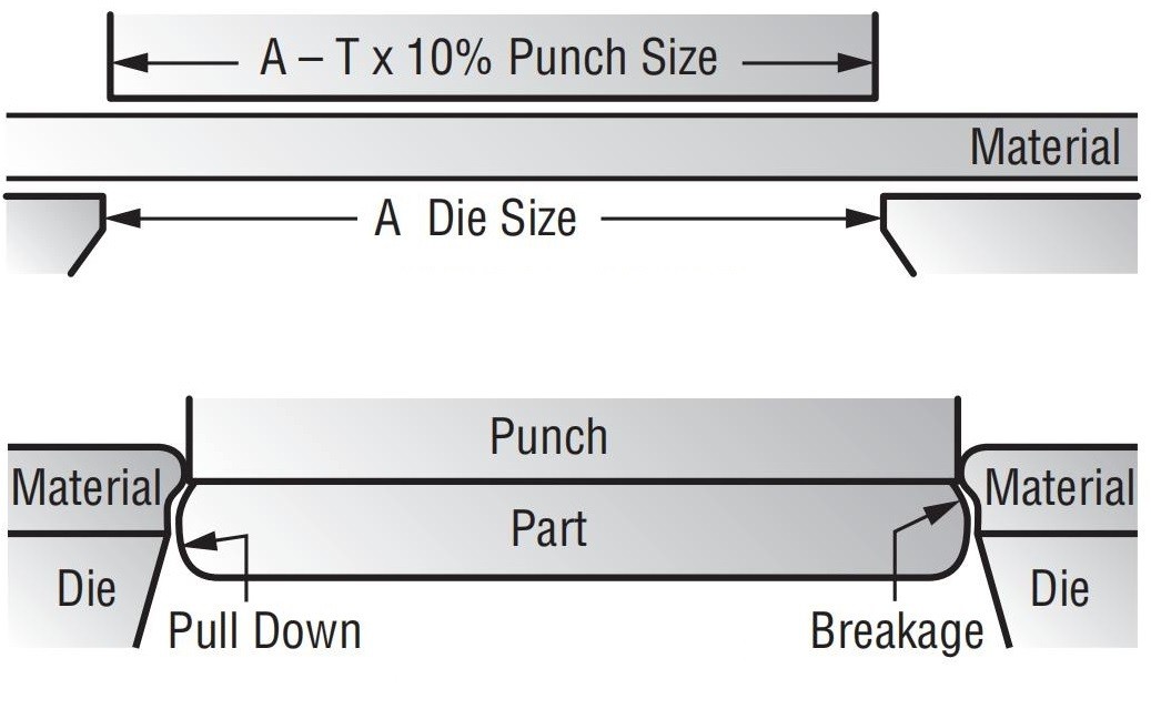
2.0Pull-Down
The extent of pull-down depends on:
- a) Material temper– Softer materials result in greater pull-down.
- b) Material structure– Long-grain materials (e.g., copper, stainless steel) tend to flow more, increasing pull-down.
- c) Material thickness– Thicker materials show more pull-down than thinner ones.
3.0Breakage
Breakage is influenced by:
- a) Material temper– Harder materials (via rolling or heat treatment) produce more breakage.
- b) Material structure– Short-grain materials (e.g., aluminum, high carbon steel) exhibit higher breakage percentages.
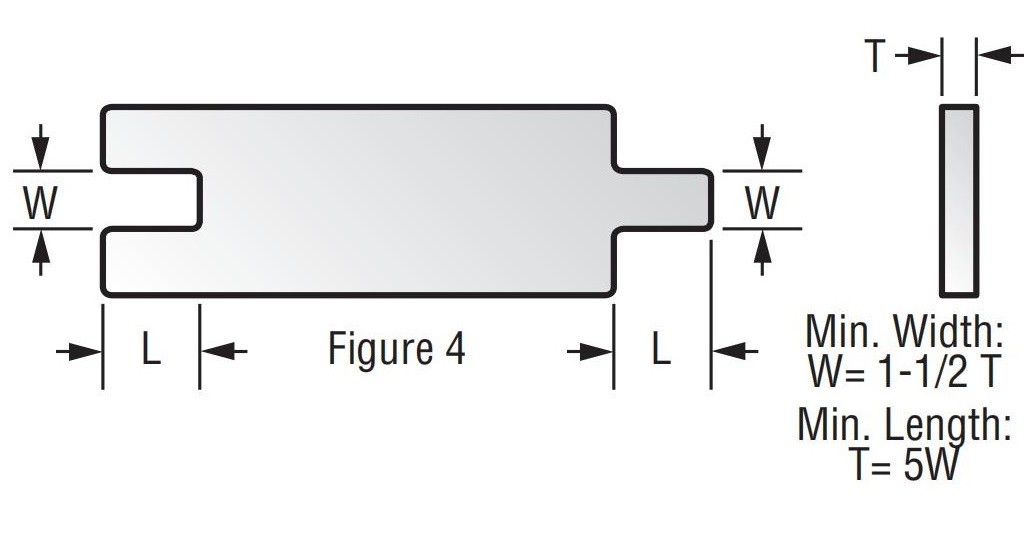
4.0Blank Design – Minimum Blank Sections
The minimum width of a blank section (W) should be:
- No less than 5 to 2 times the material thickness (T)
- Never less than 1/32 inch
The maximum length of the section should not exceed 5 times its width.
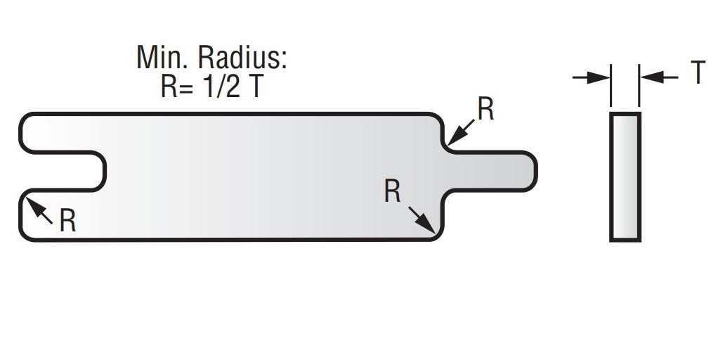
5.0Corners
Corner radius (R) should be at least ½ of the material thickness (T).
For material ≤ 1/16″, sharp corners are acceptable.
6.0Notches
If a notch requires tight size or location tolerances, consider two options:
- Rounded corner(maximum radius) if included in the blanking operation
- Sharp corner if done in a secondary operation
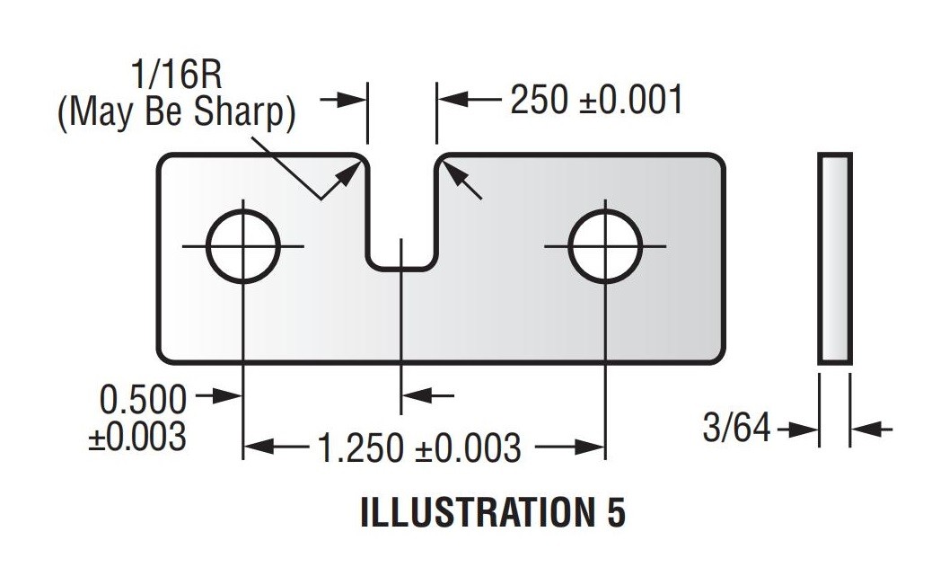
7.0Specifying Cutoffs
After shearing the blank to the correct width, multiple cutoff shapes can be specified for cost-effective stamping.
8.0Specifying Holes – Minimum Diameters
For the general economy:
- Hole diameter ≥ material thickness (T)
- For soft materials(e.g., aluminum), smaller holes are possible, but the minimum diameter should increase with material shear strength
- For stainless steel, the hole diameter should be at least 2× material thickness
- If diameter < material thickness or < 0.050″, the hole must be drilled and deburred, adding cost
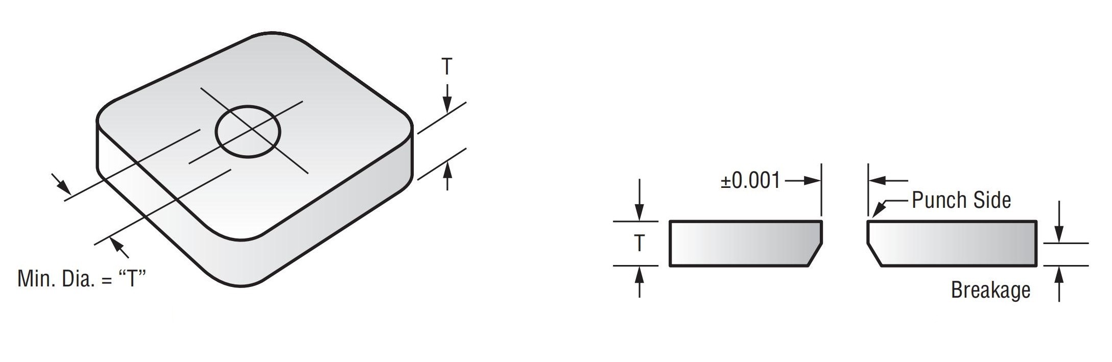
9.0Hole Tolerance
- Unless otherwise noted, tolerances apply to the punch side only
- All punched holes have breakage on the die side due to punch–die clearance
- Breakage varies by material type
- For smooth holes, punch undersize and the final dimension (adds cost)
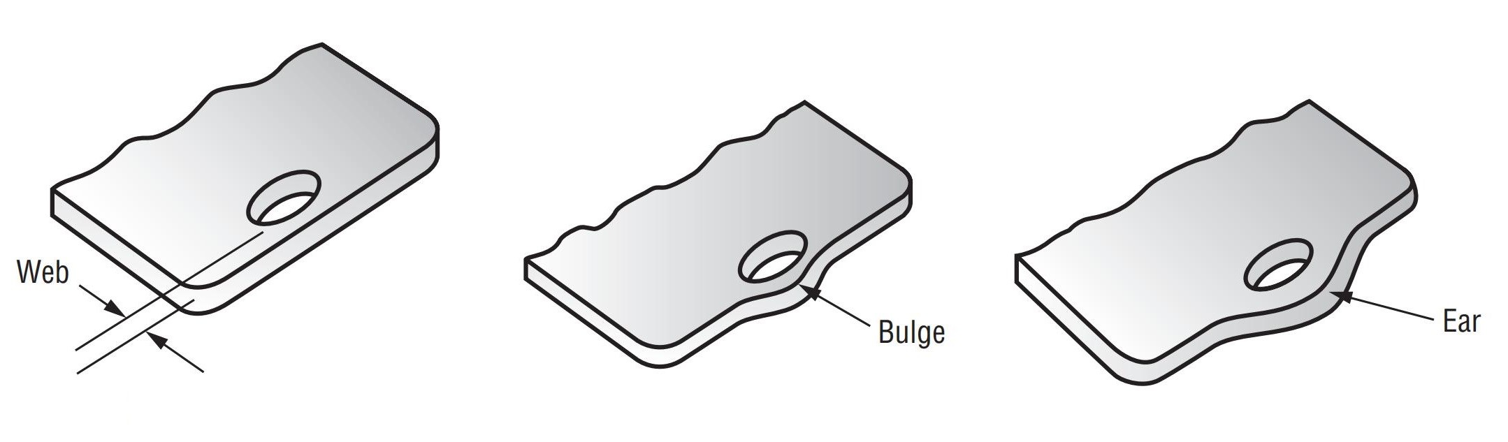
10.0Holes and Openings Near Blank Edge
To avoid bulging, maintain a web ≥ 1.5× material thickness between the hole and blank edge
If web < 1.5×T, material may bulge or fracture
Bulge becomes severe when the web is reduced below 0.5×T
The same rule applies to webs between adjacent holes
If the bulge is unacceptable, drilling + deburring is required
As an alternative, modify the blank profile by adding an ear to maintain spacing
11.0Notches as Hole Substitutes
Instead of punching a round hole, consider designing a notch in the blank contour:
The notch can be punched directly if tolerances allow
Or it can be made wide enough to be included in the blanking operation without secondary punching
12.0Holes and Openings Near Bends
To avoid distortion, holes near bends must follow this minimum distance rule:
Distance = 1.5 × Material Thickness + Bend Radius
If placed closer, distortion may occur
If distortion is unacceptable, punch the hole after forming (adds cost)
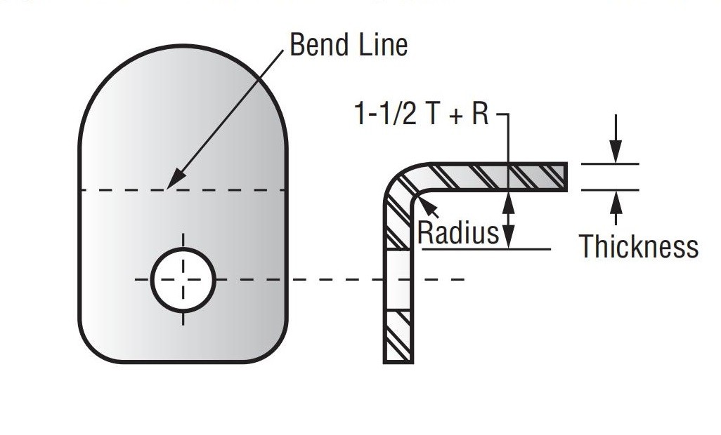
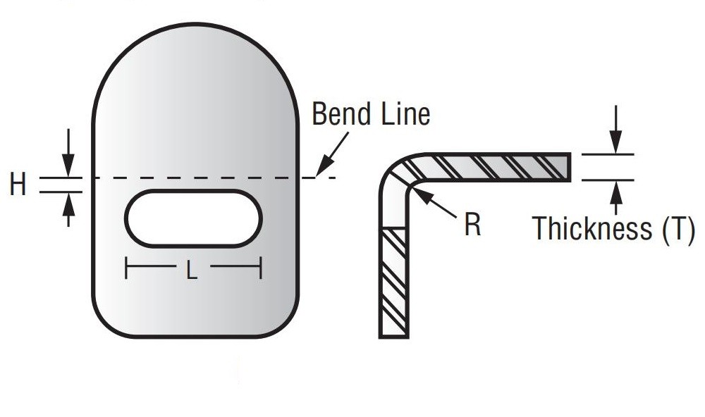
13.0Minimum Requirements for Hole Location
Use the following chart for minimum height (H) from hole center to part edge based on flange length (L):
- L ≤ 1″→ H = 2T + R
- 1″ < L ≤ 2″→ H = 5T + R
- L > 2″→ H = 3T to 3.5T + R
Hole function should guide design simplicity. Provide complete details for best cost efficiency.
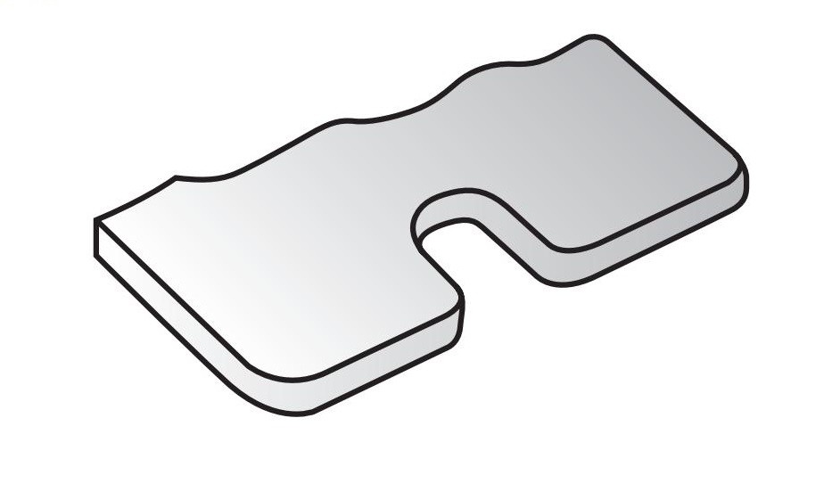
14.0Specifying Internal Tabs
Review tab function to avoid unnecessary operations:
- A relief slot around the tab allows for bending
- If other features are being punched, the slot can be added simultaneously
- If not, it may require a secondary operation
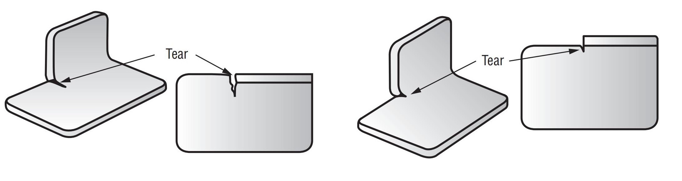
15.0Specifying Bends
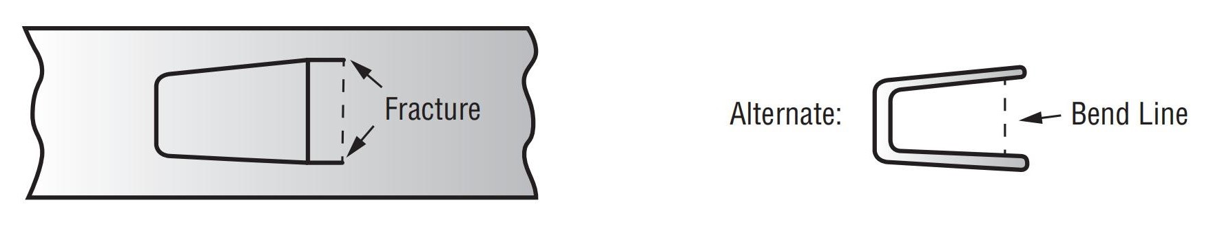
Avoiding Tearing in Formed Areas
When designing bends in stamped parts, material tearing can occur if proper relief is not provided. To prevent this:
- Add offset relief in the blank profile near the bend (Figure 16 & 17)
- Without relief, the tear will likely propagate under stress, causing fatigue failure
- Standard tooling cannot accommodate forms that lack adjacent flat areas for support — this increases tooling cost
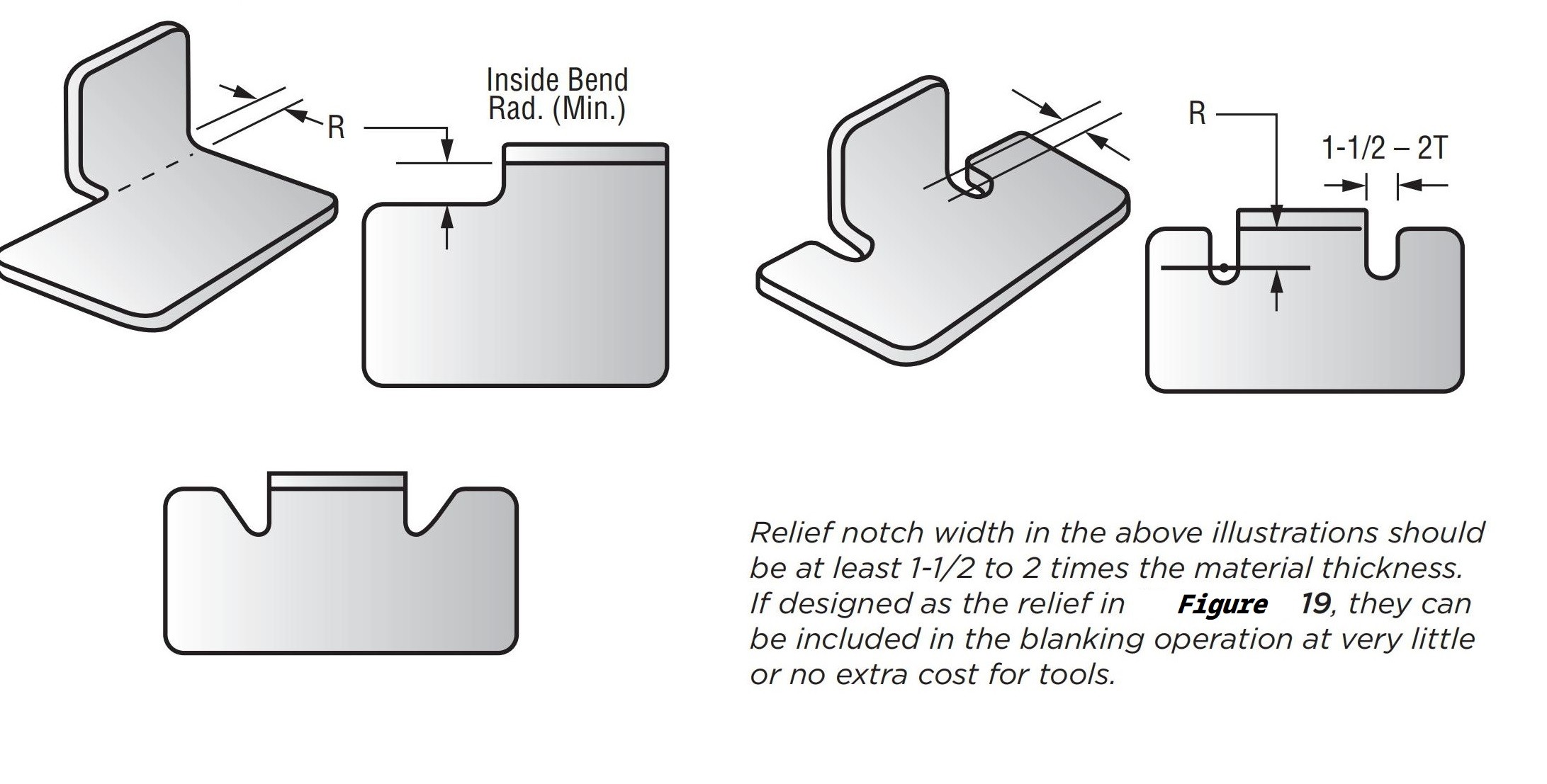
Design Solution: Relief Notch
By modifying the blank profile (Figures 18 & 19), tear lines can be eliminated:
- Relief allows the use of stock 90° punches and dies
- This results in higher part quality and lower tooling costs
- Relief notch width should be at least 5 to 2 times material thickness (T)
- If shaped like in Figure 19, the notch can be included in blanking at little or no extra cost
Form Height Consideration
Solution:
- Add material height (H)before forming and trim after
- This requires an additional operation, increasing the cost
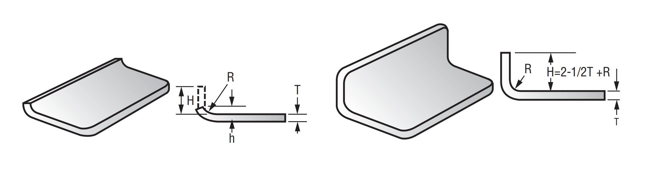
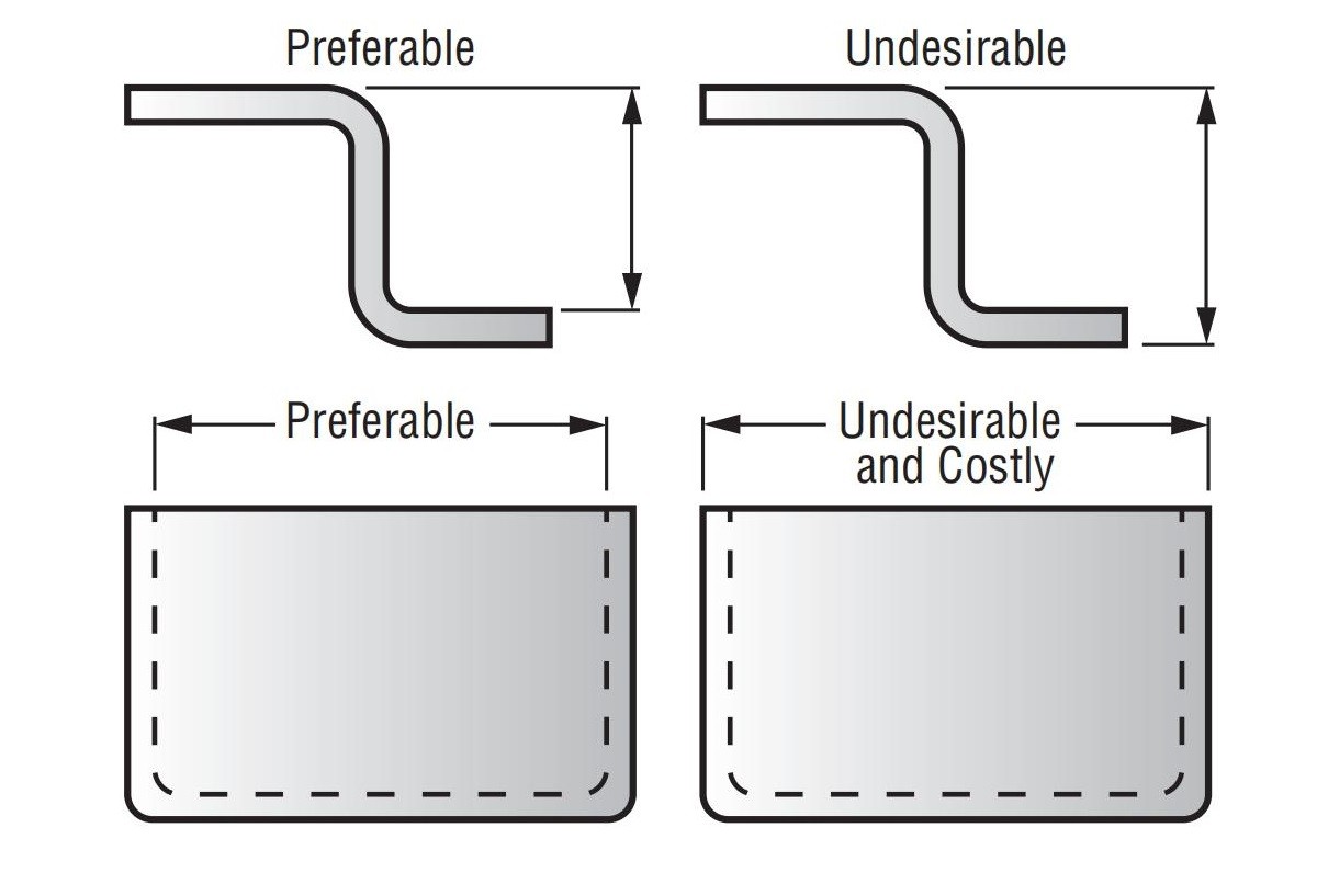
Bend Height Rule of Thumb
Use this formula for minimum inside form height (Figure 22):
H = 2.5T + R
Where:
T = Material Thickness
R = Inside Bend Radius
For soft materials (Aluminum, Brass, Copper, Mild Steel), reduce H by ~20%
This guideline balances material formability, tooling cost, and production efficiency.
Figure 21 shows poor form design — a 90° bend attempted with insufficient material height, leading to forming defects.
| Minimum Inside Height of Form“H” | |||||
| “T” Stock Thickness |
Inside Bend Radius | ||||
| Sharp “R” |
1/32 “R” |
1/16 “R” |
3/32 “R” |
1/8 “R” |
|
| 1/32 | 5/64 | 7/64 | 9/64 | 11/64 | 13/64 |
| 1/16 | 5/32 | 3/16 | 7/32 | 1/4 | 9/32 |
| 3/32 | 15/64 | 17/64 | 19/64 | 21/64 | 23/64 |
| 1/8 | 5/16 | 11/32 | 3/8 | 13/32 | 7/16 |
| 5/32 | 25/64 | 27/64 | 29/64 | 31/64 | 33/64 |
| 3/16 | 15/32 | 1/2 | 17/32 | 9/16 | 19/32 |
16.0Bending – Bulging, Fracture, and Burr Side Considerations
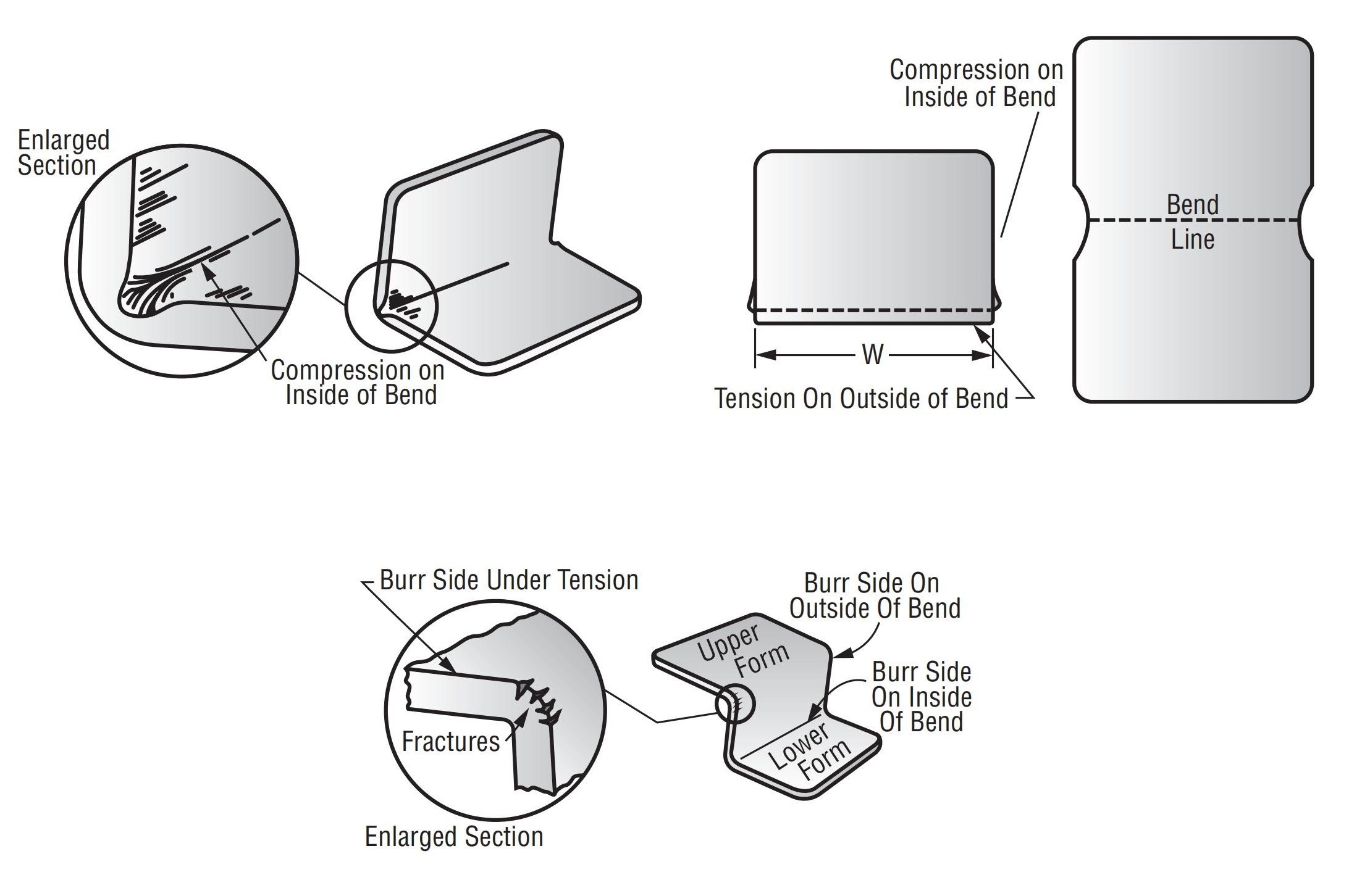
Edge Distortion (Bulging)
When thick materials are bent with a small inside radius, noticeable edge bulging may occur (See Figures 23 & 24).
Cause: Compression on the inside of the bend and tension on the outside edges
Not an issue for material < 1/16” or when bend radius is large relative to thickness
This is standard practice and usually not a concern
Exception:
If bulging interferes with a mating part, note it on the drawing so a secondary operation (e.g., edge trimming) can be planned — which will increase cost.
Controlling Width (W) Across the Bend
If width must be held across the form, use relief notches (See Figure 24).
Fracture at the Burr Side
- When the burr side of the blank is on the outside of the bend, it is under tension.
- This can lead to minute fractures along sharp edges, especially in thick material and sharp bends (See Figure 25)
- Burr-side fractures are minimal in thin materials or when bend radii are large
Minimizing Fracture
Best practice: Keep burr side inside the bend (under compression)
If not possible (due to part orientation or print requirements):
– Tumble/deburr before forming
– For difficult materials (e.g., SAE 4130) or extra heavy stock, manual filing or sanding may be required
These are secondary operations and will add to cost.
For best economy, specify generous bend radii if the burr side must be outside
If slight fractures are acceptable, clearly note this on the print
Special Note on Aluminum Alloys
Tempered aluminum alloys require much larger bend radii than steel alloys
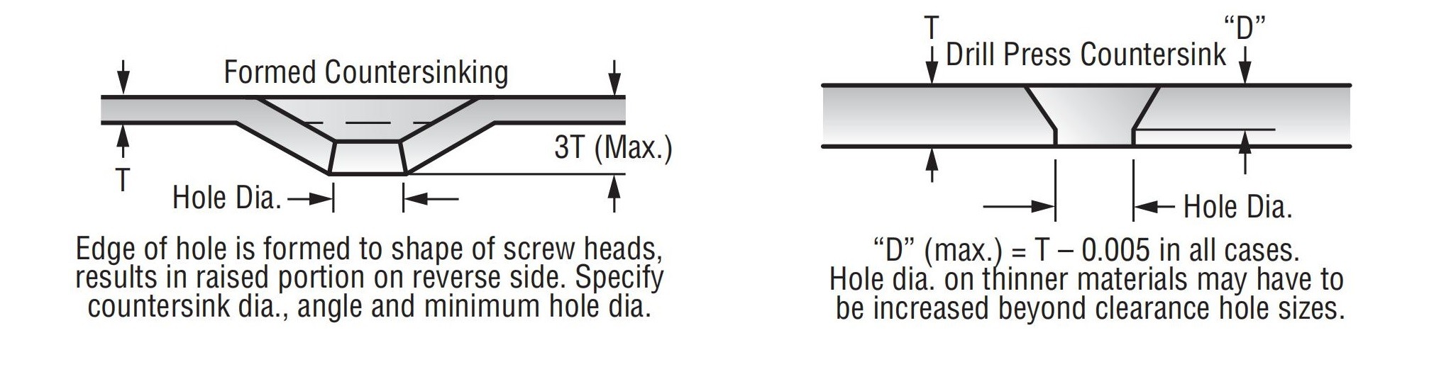
17.0Specifying Countersinking
A. Formed Countersinking
- The edge of the hole is formed to match the screw head shape
- Leaves a raised portion on the opposite side
- Advantages: Stronger, more economical, especially in soft materials
- Specify: Countersink diameter, angle, and minimum hole diameter
- Max countersink depth≈ 3× material thickness
B. Drill Press (Cut) Countersinking
- Machined into a part using a drill press
- hole dia. (D)= T – 0.005″
- In thin materials, the hole diameter may need to exceed standard clearance sizes
Two common methods (See Figures 26 & 27):
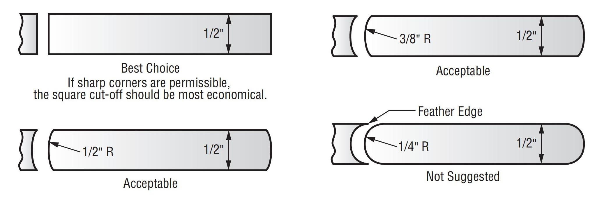
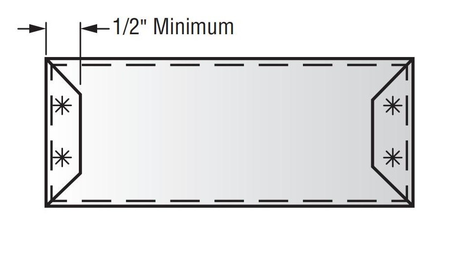
18.0Spot Weld Tips
When spot welding a flange to a main body, the minimum flange width should be ½ inch
Flanges narrower than ½” require special weld tips and may result in weaker weld strength
19.0Dimensioning
Always dimension to the inside of the material whenever possible
This avoids variation caused by material thickness and preserves tolerance accuracy
Especially important in drawn parts, where material thinning can occur
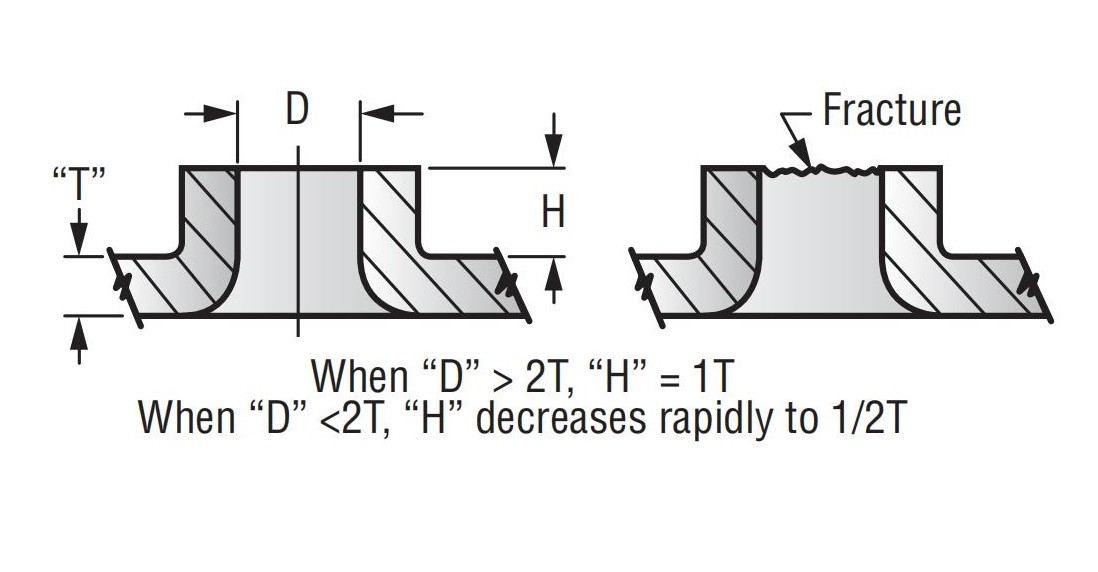
20.0Extrusions
Rule of Thumb:
- When D ≥ 2T, then H ≈ 1T
- When D < 2T, H rapidly drops to ~½T
Extrusions increase local thickness for tapping threads or creating bearing surfaces.
Design guidelines:
- Max extrusion height (H) ≈ 1× material thickness (T)
- H > 1Toften causes tearing or fracture, especially in harder materials
- Extrusion height decreases with a smaller hole diameter (D)
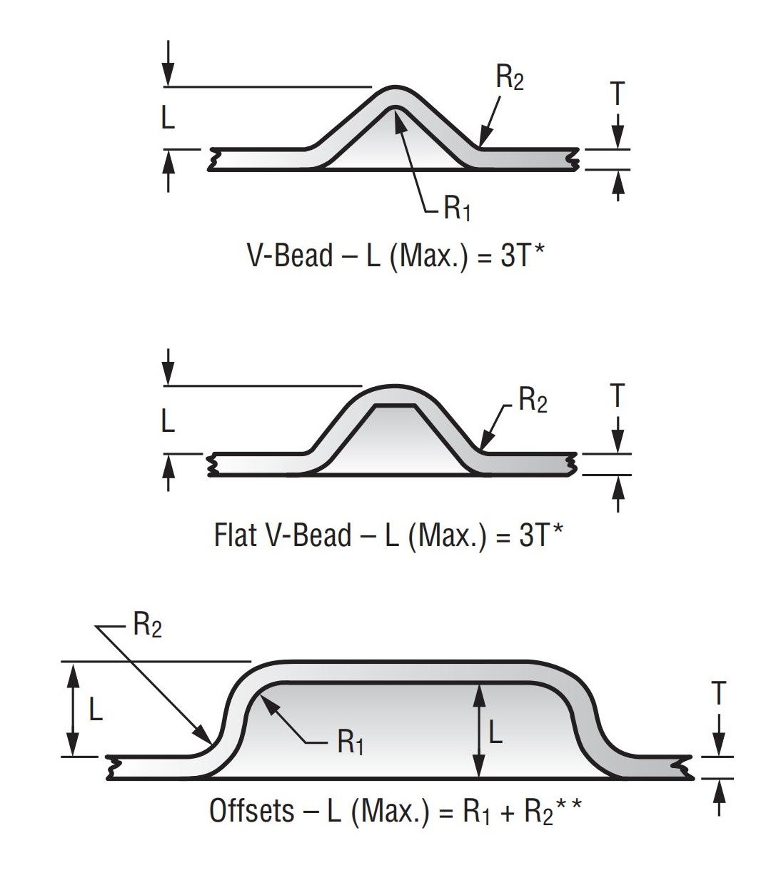
21.0Embossed Stampings
- Max emboss depth (L)should follow:
L ≤ R₁ + R₂ for offsets - Exceeding limits leads to cracking, rejects, and increased cost
Reduction Guidelines (for commercial-grade steel and most aluminum alloys):
- Reduce to 2T for embosses
- For offsets, reduce to 5 × (R₁ + R₂)
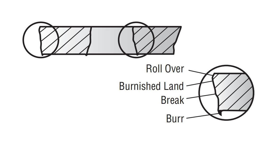
22.0Burr Removal
- All stamped parts will have burrs— sharp or ragged material along cut edges
- Typical allowance: burr height ≈ 10% of stock thickness
- Tumbling or sanding is standard when requested and feasible
- Special edge finishes(e.g., chamfering, hand deburring) are available at additional cost
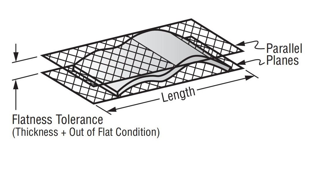
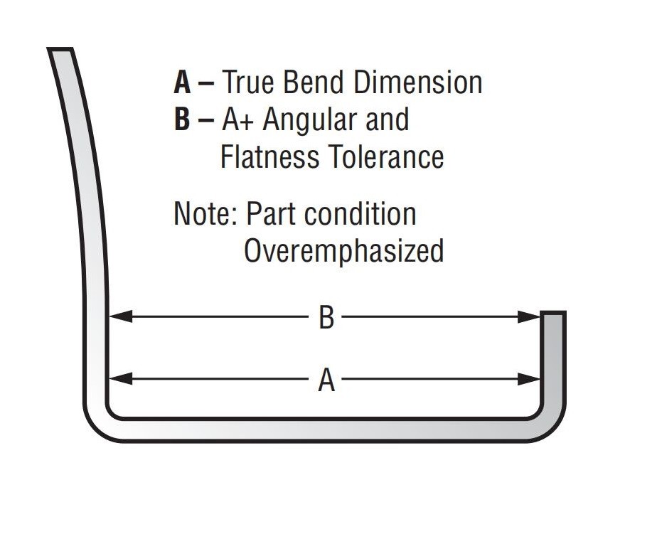
23.0Flatness
No stamping process yields a perfectly flat surface. Flatness requirements that exceed the standard tolerances below will significantly increase the cost of your stamped parts:
For surface lengths from 0″ to 1″: allow a tolerance of ±0.005″
For lengths over 4″: allow 0.020″ plus an additional 0.004″ for each inch of added length
Special flattening operations are available upon request to achieve tighter flatness, but these will incur additional costs.
24.0Surface Finish on Stamped Parts
Dull · Semi-Luster · Bright
As a general rule, the brighter the finish, the higher the cost.
Raw metal stock varies in surface finish. Typically, brighter finishes come at a higher base material cost. Furthermore, the stamping process can alter the surface finish significantly. Therefore, it is important to define the minimum acceptable surface finish to optimize cost savings.
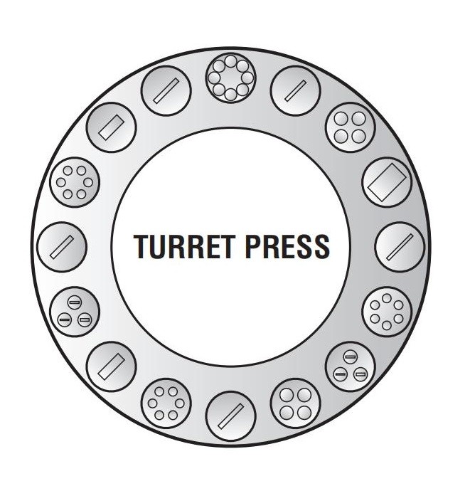
25.0Turret Press Dimensioning
For turret punching projects, provide detailed part drawings alongside your explanation. Clear communication and accurate documentation are key to ensuring a high-quality and cost-effective result. Follow these steps:
- Establish a fixed starting point (datum)— preferably at a hole center rather than an edge or corner. This helps prevent misalignment and distortion caused by clamping. It also improves accuracy, especially when material taper is present, and simplifies inspection with fewer reference points.
- Use a single dimension from the datum to define the general layout. Related hole patterns should be dimensioned relative to this starting point to maintain function and precision.
- Highlight all critical dimensions— clearly indicate any dimensional relationships that affect the function of the part.
26.0Press Brake Dimensioning Best Practices
Key Guidelines:
- Measure adjacent to the bend radius.
This reduces the error caused by angular and flatness variations. - Use single-direction dimensioning whenever possible.
This minimizes tolerance accumulation throughout the sequential bending operations. - Account for dimensional variation at each bend.
Each bend introduces potential variance. To achieve accuracy, consider these variations during part design and dimensioning. - Ensure proper clamping or fixturing.
Thin sheet metal parts must be securely held during forming to prevent cumulative tolerance issues. Proper fixturing aligns with the standard shown above. - Avoid feature-to-feature dimensions across different planes.
Instead, dimension features are relative to a fixed edge. This may require the use of custom clamps or gauges but provides more reliable results. - Review title block tolerances carefully.
General tolerances in the part drawing may be too restrictive for certain angles and dimensions. Always verify whether such tolerances are suitable for your application.
27.0Laser Cutting Combined with Turret Punching
Laser cutting has become a cornerstone in modern metal fabrication, especially as short production runs, rapid turnaround, and just-in-time manufacturing become increasingly standard. Modern laser systems are designed to support these demands with high speed and precision.
Integration with Turret Punching:
Laser and turret punch technologies can be used either:
- Independently, as standalone machines, or
- Together, in integrated laser-turret combination systems
These systems allow manufacturers to:
- Achieve complex hole patterns and irregular profile cuts
- Maintain high precision and fast processing speeds
Before combining punching and laser cutting processes, it is essential to:
- Evaluate machine capabilities for your specific project requirements
- Ensure the equipment can handle both operations efficiently to produce accurate, cost-effective parts
- Laser Turret Combo Machine
Ideal for versatile, high-speed, high-accuracy operations involving both cutting and punching.
28.0Designing Parts for Laser Processing
Minimum Feature Size
Unlike punch presses, laser cutting does not follow the same limitations regarding minimum hole size or spacing between features.
- A typical laser beam has a focused spot size of approximately 010 in. (0.2 mm)
- It can cut features with a radius as small as 030 in. (0.76 mm)
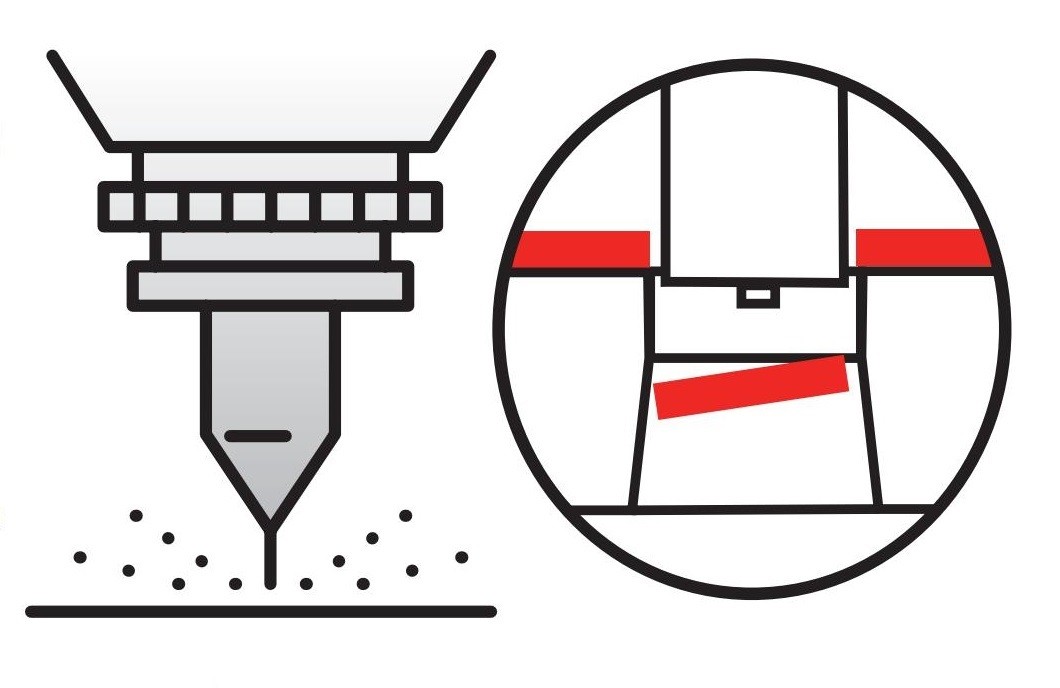
Edge Taper Accuracy
The laser is most precise at the beam entry point, where the hole is slightly smaller. The exit point typically shows a marginally larger diameter due to edge taper.
- This edge condition resembles that of pierced or sheared surfaces
- A secondary finishing operation may be needed depending on the application
- Consider the functional side of the part when choosing which surface to laser cut
Micro Tabs
Micro tabs are small, uncut sections used to hold parts in place during cutting, which prevent shifting and reduce distortion.
- Typical tab size: 25 mm to 5 mm
- Minimal removal force is required, often eliminating the need for additional finishing
- Useful in applications such as tightly spaced vents and fine internal features
Heat-Affected Zone (HAZ)
Laser cutting generates intense localized heat, which melts and vaporizes the metal. The extent of the heat-affected zone depends on the material type and thickness.
- Heat-treated materials may become case-hardened in the laser-cut area
- This may pose challenges for secondary operations like reaming or countersinking
- However, intentional case hardening via laser can be leveraged to increase wear resistance and component longevity
Tolerance Accumulation
As with any manufacturing process—punching, cutting, or bending—laser-processed parts are subject to cumulative tolerances.
- It is essential to identify and communicate critical dimensions during the design stage
- Prioritizing functional tolerances helps achieve high-quality, cost-efficient results
Note:
Laser processing is ideal for prototyping, small batch production, and complex geometries—but proper design communication is key to maximizing its advantages.