

- 1.0Introduction to Machining Economics
- 2.0Stock Selection: Near-Net Shape vs. Standard Rectangular Stock
- 3.0Operation Planning and Tool Selection
- 4.0Feed Rate Optimization: Roughing vs. Finishing
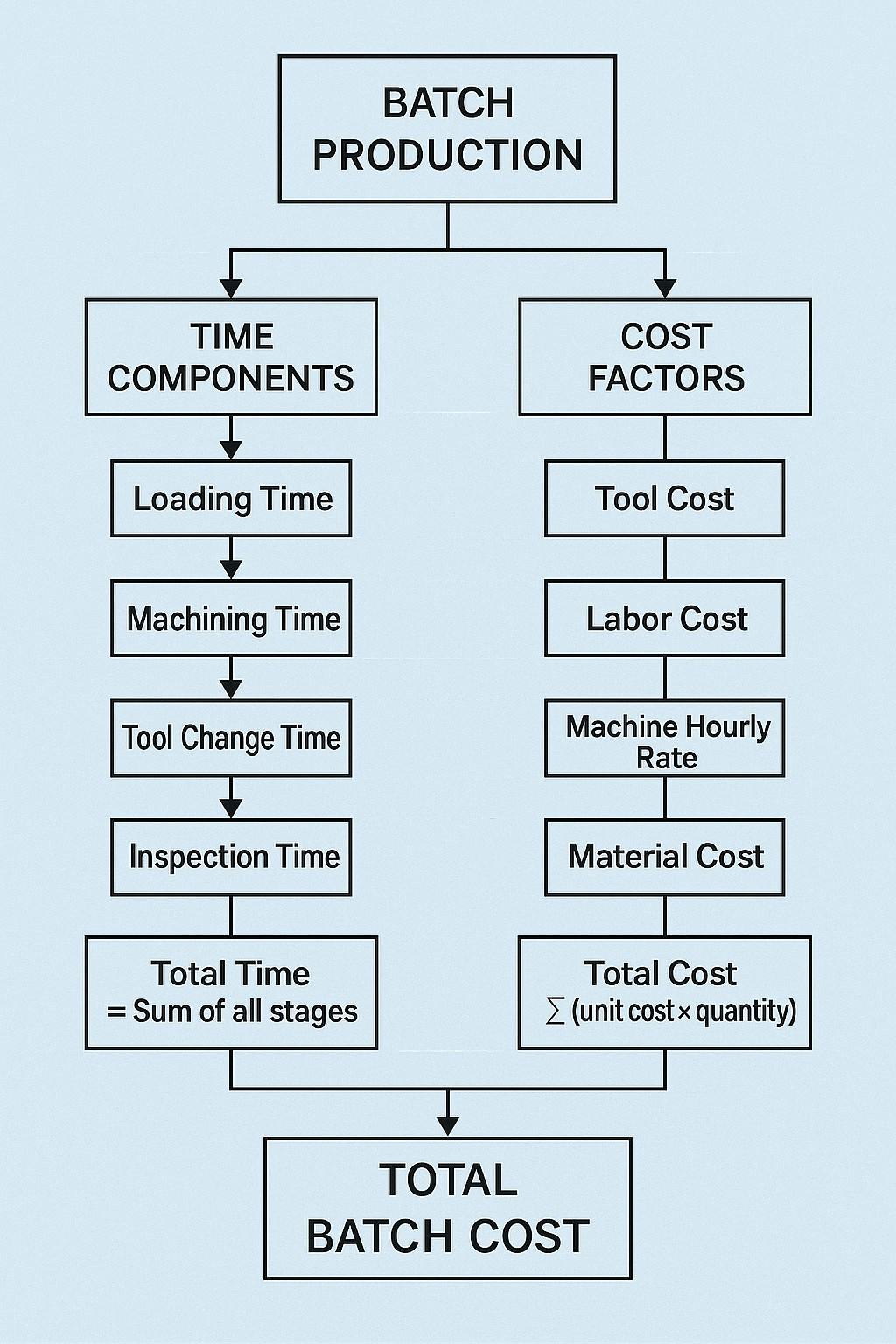
- 5.0Modeling Production Cost in Batch Manufacturing
- 6.0Tool Wear and Taylor’s Tool Life Equation
- 7.0Optimizing Cutting Speed
- 8.0Summary and Practical Guidelines
- 9.0Closing Thoughts
In the field of high-precision manufacturing, the ability to optimize machining parameters is a critical factor in operational success. Understanding and applying the principles of machining economics can lead to significant reductions in production cost and time while improving tool utilization and manufacturing throughput.
This article explores a comprehensive framework for optimizing machining processes. From initial material selection to feed rate tuning and cost modeling, each stage contributes to either minimizing cost or maximizing production rate. The objective is to equip engineers, production planners, and machinists with practical strategies grounded in data and real-world production constraints.
1.0Introduction to Machining Economics
At its core, machining economics involves optimizing machining operations to meet one of two goals:
- Maximize the production rate (i.e., minimize cycle time), or
- Minimize the production cost (i.e., achieve economic efficiency)
Achieving either objective requires a structured approach to several critical decision points, including:
- Selection of starting stock
- Operation planning and tool selection
- Feed rate and cutting speed optimization
- Tool wear modeling
- Cost and time analysis for batch production
By modeling and optimizing these stages, manufacturers can increase profitability, improve asset utilization, and gain competitive advantage in sectors such as aerospace, automotive, mold and die, and precision components.
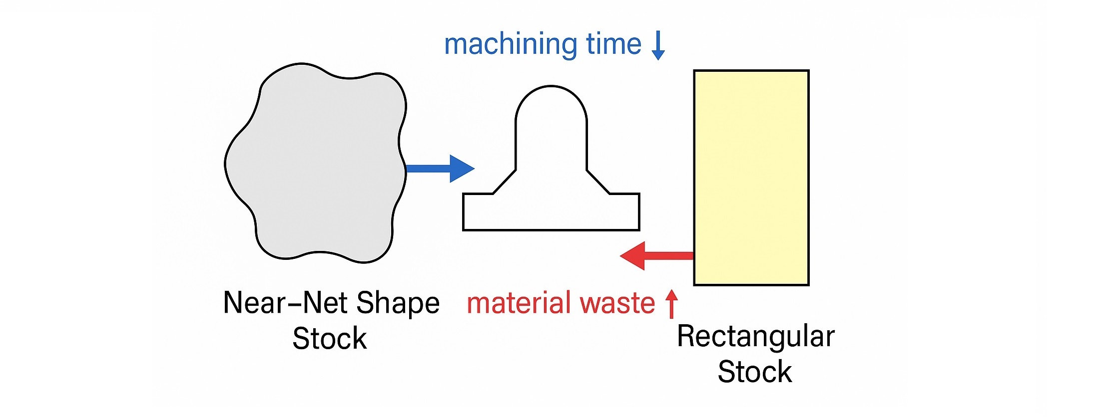
2.0Stock Selection: Near-Net Shape vs. Standard Rectangular Stock
Before any machining operation begins, the choice of raw material stock significantly influences both cost and time.
2.1Near-Net Shape Stock
Near-net shape refers to materials that closely match the final geometry of the part.
- Advantages:
- Significantly reduces machining time
- Generates less scrap material
- Requires fewer passes and tools
- Disadvantages:
- Typically higher in cost due to custom casting or forming
- May have longer lead times
This option is ideal when cycle time is critical or when working with expensive or difficult-to-machine materials (e.g., titanium alloys).
2.2Rectangular Stock (e.g., mold base blocks)
Most common in general-purpose machining, rectangular stock offers cost and availability advantages.
- Advantages:
- Widely available and relatively low-cost
- Standardized dimensions and tolerances
- Disadvantages:
- Requires greater material removal
- Increases tool wear and machining time
Key Strategy: Always select the smallest stock dimension that can safely contain the final part. Oversized stock increases waste and energy consumption without adding value.
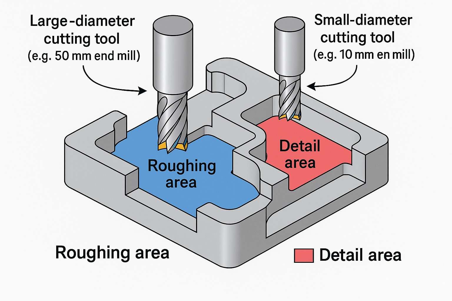
3.0Operation Planning and Tool Selection
The material removal rate (MRR) is a fundamental metric in machining productivity. Selecting the appropriate tools and defining machining regions directly affects MRR and overall efficiency.
3.1Tool Diameter and Feature Size
- Large tools are preferred for bulk removal and high MRR in roughing operations.
- Small tools are necessary for intricate features, tight radii, or finishing passes.
Recommended Practice: Break down the part into feature-based sub-regions. Assign each region the largest tool that can fit, ensuring maximum removal rate while maintaining accuracy.
This approach minimizes tool changes, reduces machining time, and improves toolpath efficiency.
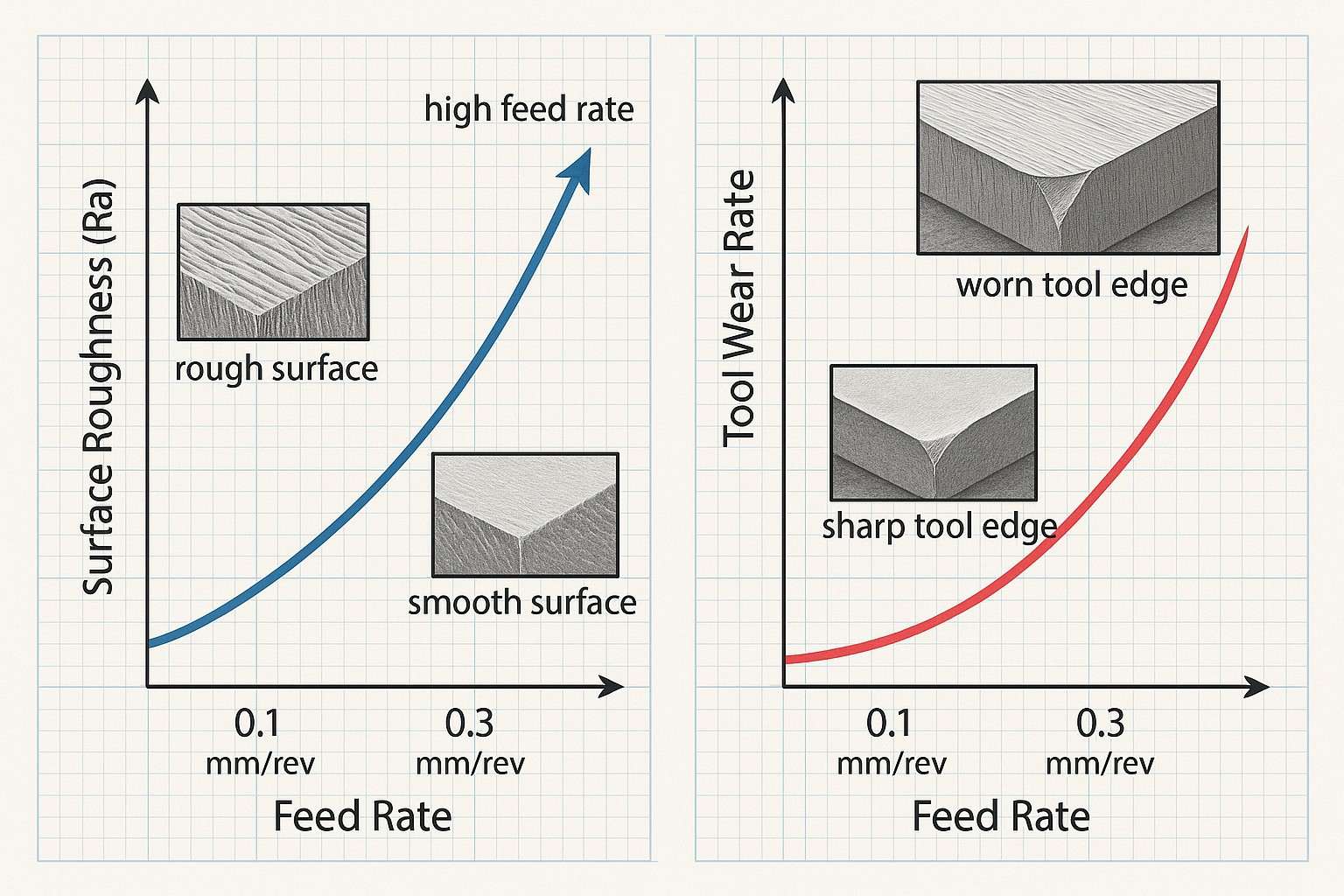
4.0Feed Rate Optimization: Roughing vs. Finishing
Feed rate directly influences the MRR, surface quality, tool life, and cutting forces.
4.1Finishing Operations
- Higher feed rates increase productivity but degrade surface finish.
- The optimal feed rate is the highest value that still meets surface quality requirements, which depend on:
- Functional tolerances
- Aesthetic or cosmetic standards
- Fit and assembly criteria
- Post-processing operations such as polishing or coating
4.2Roughing Operations
Surface finish is less important since a finishing pass will follow. The focus here is on maximizing MRR through:
-
Higher cutting speed (V)
-
Higher feed rate (f)
However, increasing V and f also raises tool temperature, which in turn affects wear and tool life.
-
Cutting speed increases chip velocity
-
Feed rate increases the cross-sectional area of the chip
4.3Tool Force and Power Considerations
-
Cutting force is proportional to feed rate
-
Higher force requires:
-
Greater machine power
-
Tools rated for higher cutting loads
-
Optimization Guideline: The optimal roughing feed rate is the highest value that satisfies:
- The machine’s power capacity
- The tool’s maximum cutting force limit (as specified by the manufacturer)
5.0Modeling Production Cost in Batch Manufacturing
In batch production, the total unit cost is influenced by both productive and non-productive operations.
Assume a batch of NbN_b identical parts is produced. The time and cost components are as follows:
5.1Time Components
-
Non-productive time tlt_l: Includes loading, setup, and unloading.
Total non-productive time = Nb⋅tlN_b \cdot t_l -
Machining time tmt_m: Time to machine a single part.
Total machining time = Nb⋅tmN_b \cdot t_m -
Tool change time tct_c: Time required to replace a worn tool.
Total = Nt⋅tcN_t \cdot t_c, where Nt=Nb⋅tmTN_t = \frac{N_b \cdot t_m}{T}
5.2Cost Components
-
CtC_t: Cost per tool
-
MM: Machine and labor cost per minute
The average cost per part is modeled as:
$$
C_{pr}(V) = t_l \cdot M + t_m \cdot M + \frac{C_t \cdot t_m}{T} + \frac{t_c \cdot M \cdot t_m}{T}
$$
This equation clearly shows how tool life TT — a function of cutting speed — influences total cost.
6.0Tool Wear and Taylor’s Tool Life Equation
Tool wear must be modeled to optimize cutting parameters accurately. The widely used Taylor’s tool life equation is:
$$
V \cdot T^n = C
$$
Where:
- VV: Cutting speed
- TT: Tool life
- n,Cn, C: Empirical constants based on tool-workpiece material combination
Solving for tool life:
$$
T = \left( \frac{C}{V} \right)^{1/n}
$$
Substituting into the cost model:
$$
C_{pr}(V) = t_l \cdot M + t_m \cdot M + \frac{C_t \cdot t_m}{T} + \frac{t_c \cdot M \cdot t_m}{T}
$$
This defines cost per part as a function of cutting speed VV.
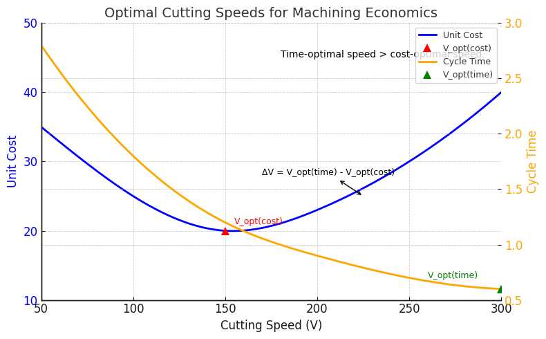
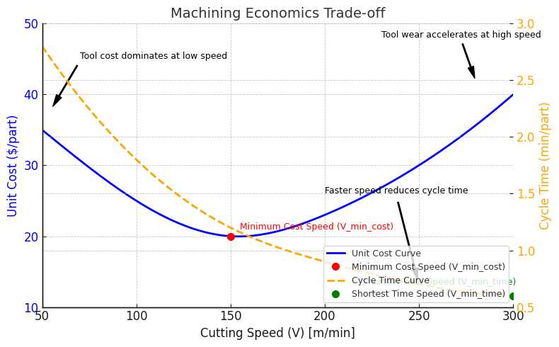
7.0Optimizing Cutting Speed
7.1Optimum Speed for Minimum Cost
To minimize unit cost, differentiate the cost function with respect to cutting speed VV and set the derivative to zero:
$$
\frac{d C_{pr}(V)}{dV} = 0
$$
Solving this yields the optimum cutting speed for minimum cost, denoted as:
$$
V_{opt}^{(cost)}
$$
This is typically lower than the speed that minimizes production time, due to higher tool life at lower speeds.
7.2Optimum Speed for Maximum Production Rate
The average time per part is modeled as:
$$
T_{avg}(V) = t_l + t_m + \frac{t_c \cdot t_m}{T}
$$
Substituting for TT, the expression becomes a function of VV. To minimize time:
$$
\frac{d T_{avg}(V)}{dV} = 0
$$
Solving this yields the optimum speed for minimum time:
$$
V_{opt}^{(time)}
$$
Typically,
$$
V_{opt}^{(time)} > V_{opt}^{(cost)}
$$
since higher speed shortens cycle time but increases tool consumption.
8.0Summary and Practical Guidelines
Key Takeaways:
- Material Selection: Use near-net shapes to reduce machining time when cost allows; otherwise, optimize standard stock size for minimum waste.
- Tool Strategy: Segment parts by feature size and use the largest allowable tool in each region to maximize MRR.
- Feed Rate Tuning:
- For finishing: Set the highest feed that meets surface quality.
- For roughing: Push feed to the limit of machine power and tool capability.
- Cutting Speed Optimization:
- Use Taylor’s equation to model tool wear.
- Optimize speed based on your goal: lower cost vs. faster throughput.
- Batch Production Economics:
- Factor in tool change time, tool cost, and non-productive operations.
- Use cost models to select cutting speeds that balance long-term efficiency.
9.0Closing Thoughts
Machining economics provides a structured, quantitative method to improve decision-making in CNC and manual machining environments. Whether your goal is cost leadership or high-speed production, integrating these principles into CAM programming, tooling selection, and process planning can drive measurable gains in efficiency and profitability.