- 1.0What Is a Chamfer?
- 2.0Types of Chamfers
- 3.0How Is Chamfering Performed?
- 4.0What Is a Chamfered Hole and How Is It Defined?
- 5.0Chamfer vs. Radius: What’s the Difference?
- 6.0Why Is Chamfering Important?
- 7.0Common Chamfering Tool Categories & Application Guide
- 8.0Tool Selection Guide (By Application Scenario)
- 9.0What Is a Chamfered Edge in CAD?
- 10.0How to Create Chamfers in CAD
- 11.0Chamfer vs. Break Edge
- 12.0Chamfer vs. Countersink
- 13.0Chamfer vs. Deburring
- 14.0What Is a Chamfer in Engineering?
1.0What Is a Chamfer?
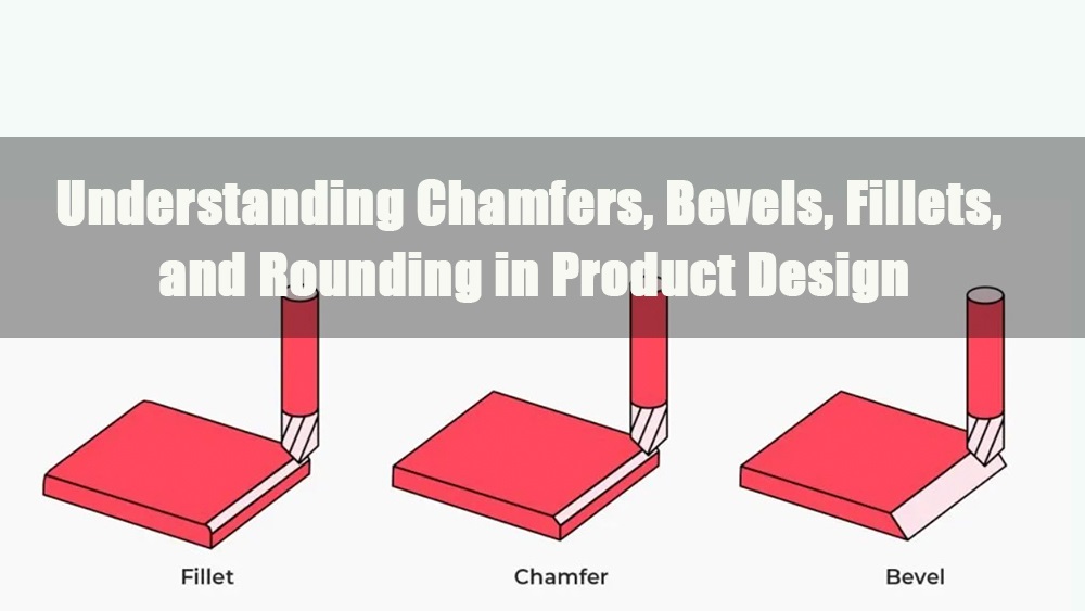
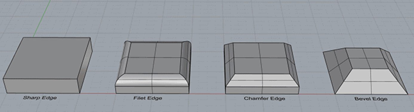
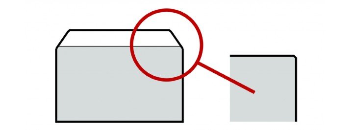
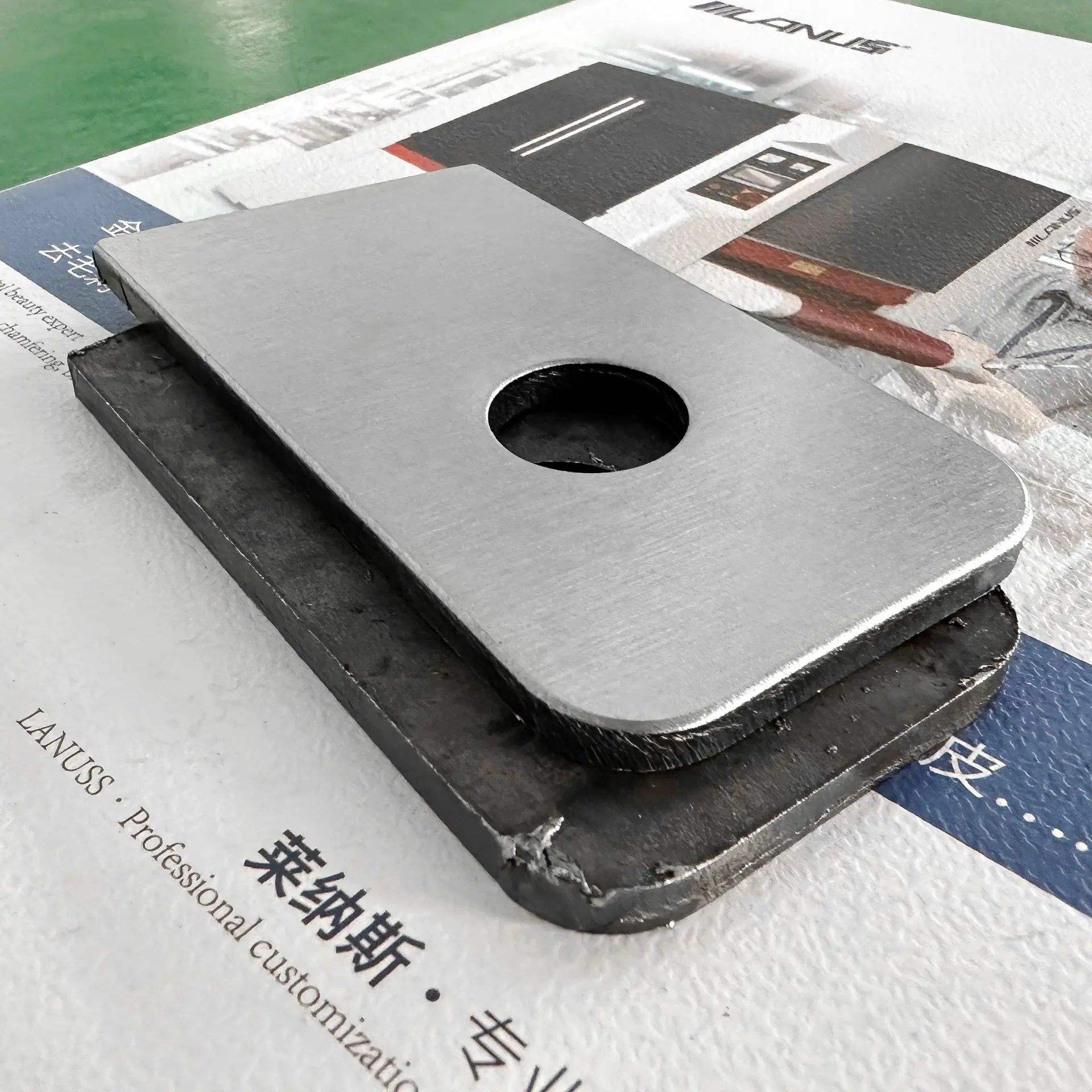
A chamfer is a common edge treatment used in machining and manufacturing to remove sharp corners from part edges. It improves functionality, enhances safety, and contributes to the part’s visual appeal.
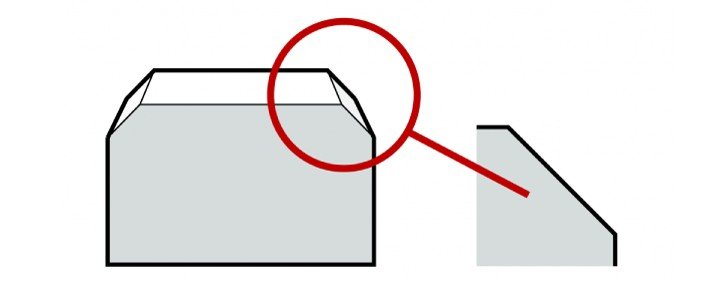
A chamfer is a flat surface set at a specific angle, typically used to replace a sharp 90-degree corner between two adjacent surfaces. Unlike a fillet, which is a rounded transition, a chamfer creates a straight-edge bevel. The most commonly used chamfer angle is 45°, though 30°, 60°, or other custom angles may be applied depending on design or functional requirements.
Chamfering is widely used on parts made from metal, plastic, and other materials. For example, the edges of laptop or smartphone enclosures are often chamfered or pressed to create a smoother touch experience and prevent discomfort during handling.
2.0Types of Chamfers
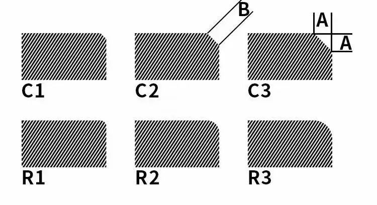
Chamfers can be categorized by geometry and application into the following common types:
- Standard Chamfer (45° Equal Distance):
This is the most common chamfer type, created by cutting equally along two adjacent surfaces, typically at a 45° angle. It offers symmetry, easy machinability, and repeatability, making it ideal for blocks, brackets, and flat parts. It is also the default chamfer option in most CAD systems. - Chamfer by Distance and Angle (Custom Angle):
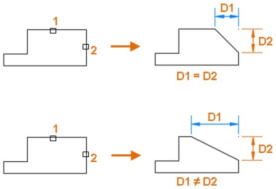
This type is defined by specifying a linear offset and a custom angle (e.g., 30°, 60°). It is used where slope precision or alignment with mating components is required. Often applied in assemblies that require guided insertion or clearance management. - Asymmetric Chamfer (Two-Distance Chamfer):
In this case, the lengths of the chamfers on the two adjacent surfaces are not equal, forming an uneven angle. Suitable when space is limited on one side or when force needs to be applied in a specific direction during assembly. Common in asymmetric mechanical designs. - Hole Edge Chamfer (Lead-In Chamfer):
Applied around the entry of a drilled or machined hole to assist in screw or bolt insertion, reduce edge damage, and protect threads. Typically designated as “C1.0 × 45°”. Common in threaded holes, locating features, and countersunk designs. - End Face Chamfer:
A beveled edge is applied around the end face of shafts, tubes, or discs. It enhances visual appearance, reduces sharp edges, and aids in alignment. In rotating components, it also helps mitigate edge wear and is often used alongside fillets to relieve stress concentrations. - Custom Chamfer Profile:
Used in high-precision or high-spec applications such as aerospace, medical devices, and tooling. These may include variable angles, curved transitions, or compound surfaces. Typically requires multi-axis CNC machining, fine grinding, or advanced 3D modeling, with definitions handled through CAD.
3.0How Is Chamfering Performed?
Chamfering can be achieved through various machining methods, depending on part geometry, required precision, and production setup. Common processes include turning, milling, drilling, and grinding.
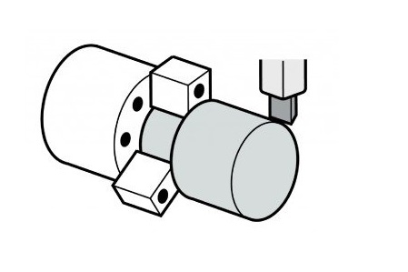
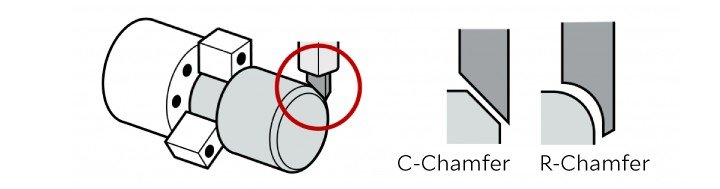
Turning Chamfers:
Best suited for cylindrical parts and is typically performed on a lathe. The cutting tool is fed into the rotating workpiece to create a beveled edge.
Common tools:
- 45° straight tool: used for C-type (linear) chamfers
- Radius tool: used for R-type (rounded) chamfers
This method is ideal for high-volume production and precision chamfering of shafts and similar components.
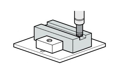
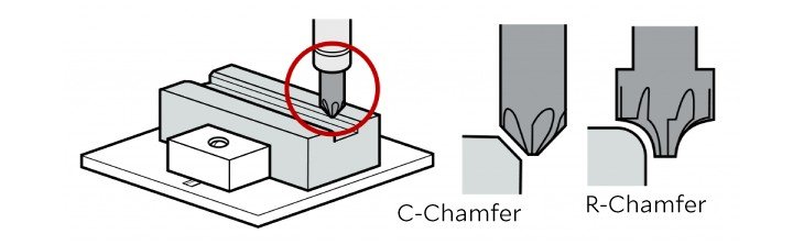
Milling Chamfers:
Used for flat surfaces or outer contours, where a rotating tool cuts the chamfer on a stationary workpiece.
Common tools:
- Chamfer milling cutter: used for C-type chamfers
- Corner rounding end mill: used for R-type chamfers
Milling offers high flexibility and is suitable for localized chamfering on complex parts.
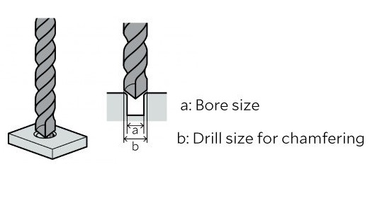
Drilling Chamfers:
Applied to hole entries by using a larger diameter drill bit to create a tapered edge. This method is quick and effective for individual holes.
Note: While efficient, this technique may create secondary burrs along the edge. A ball-end mill or specialized deburring tool is often used afterward to ensure a clean hole finish.
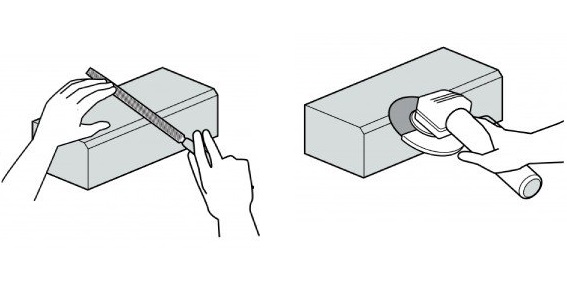
Grinding and Manual Chamfering:
Used for deburring or applying small chamfers to irregular or delicate areas.
Common tools:
- Disc grinder
- Hand file
Typically used for line chamfers or general edge smoothing. Not recommended for high-precision applications. For consistent quality in production, automated deburring systems are preferable over manual methods.
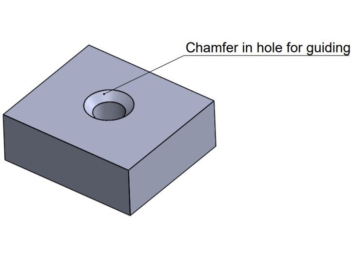
4.0What Is a Chamfered Hole and How Is It Defined?
A chamfered hole refers to a hole with its entrance edge beveled at a specific angle, typically 45°. This angled surface serves several functional purposes:
Assembly guidance: Facilitates the smooth insertion of screws, bolts, pins, bushings, and other components.
Edge protection: Reduces the risk of wear, chipping, or edge breakout around the hole.
Burr removal: In threaded holes, chamfering helps eliminate burrs that could interfere with mating parts or damage threads.
Improved structural integrity: Minimizes stress concentration around the hole, contributing to longer service life.
Chamfer Notation in Technical Drawings:
Chamfers on holes are commonly specified in one of the following formats:
C1.0 × 45°: Indicates a chamfer depth of 1.0 mm at a 45° angle.
2 × 45°: Indicates a chamfer width of 2 mm at a 45° angle.
Chamfered holes are widely used in threaded holes, dowel holes, locating holes, and countersinks. They are a standard design practice in precision engineering where reliable assembly and durability are critical.
5.0Chamfer vs. Radius: What’s the Difference?
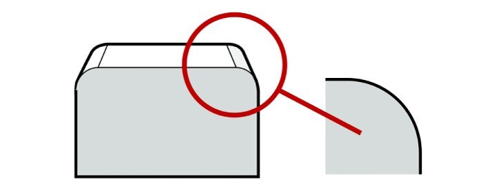
In mechanical design and manufacturing, chamfers and radii (or fillets) are both used to remove sharp edges from parts. Their purpose is to improve fit, safety, structural integrity, and appearance. However, they differ significantly in shape, application, and manufacturing approach.
| Comparison Item | Chamfer | Radius / Fillet |
| Geometry | Angled surface (typically straight) | Curved surface (smooth transition) |
| Typical Angle/Size | Usually 45°, can be 30°, 60°, etc. | Defined by radius, e.g., R1.0, R3.0 |
| Application Areas | Edges, hole entries, alignment features | External contours, corners, edge junctions |
| Design Purpose | Remove sharp edges, guide assembly, simplify mating, relieve stress | Improve appearance, strengthen corners, reduce stress concentration |
| Machining Methods | Milling, turning, and drilling | Milling, CNC machining, mold forming |
| CAD Notation | C1.0 × 45° (depth × angle) | R2.0 (radius specification) |
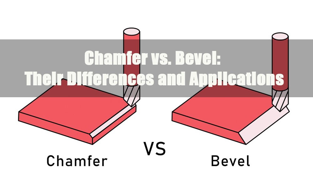
Note:Technically, a chamfer refers to a straight-angled cut, while a radius or fillet indicates a rounded transition. In informal usage, the term bevel is sometimes used interchangeably with chamfer, but in engineering drawings and CAD models, they should be clearly distinguished.
6.0Why Is Chamfering Important?
Chamfering is an essential design and manufacturing process used in high-quality parts and sheet metal fabrication. It plays a critical role in improving safety, assembly efficiency, durability, and connection performance. Key benefits include:
- Improved Safety:
Machined metal parts often retain sharp edges or burrs that can cause cuts or injuries during handling, installation, or use. Chamfering removes these sharp corners, reducing the risk of harm—especially in products that may be handled by children, where larger chamfers may be required for added protection. - Simplified Assembly:
Chamfers act as lead-ins for components like screws, pins, or fasteners. They help guide parts into mating holes, minimize interference, and reduce alignment difficulty—ultimately speeding up the assembly process. - Reduced Stress Concentration:
Sharp 90-degree edges can become points of stress concentration under load or vibration, leading to cracks or fatigue failure. Chamfers help distribute stress more evenly at critical junctions, improving overall structural reliability. - Enhanced Durability and Mechanical Integrity:
Sharp edges are prone to chipping, cracking, or delamination over time due to friction or impact. Chamfered edges provide a smoother transition, lowering the chance of damage and preventing loose debris from entering machinery—thereby reducing failure risks. - Optimized Joint Performance:
Chamfers create a better edge condition for welding, bonding, or bolted connections. They help minimize stress risers, improve sealing surfaces, and strengthen joint integrity. - Increased Manufacturing Efficiency:
In high-volume production, chamfering can be standardized and automated via CNC programming. This reduces manual finishing, enhances consistency across parts, and improves overall production throughput.
7.0Common Chamfering Tool Categories & Application Guide
Chamfering is a common finishing operation in metalworking, used to remove sharp edges, aid assembly, improve weld quality, or enhance part aesthetics. Depending on the machining method, part geometry, and application context, chamfering tools can be categorized into four main types:
7.1Chamfering Machines
- Bench-Top Chamfering Machines: Sheet metal, flat bars, pipes – High stability for batch production; adjustable angle and depth
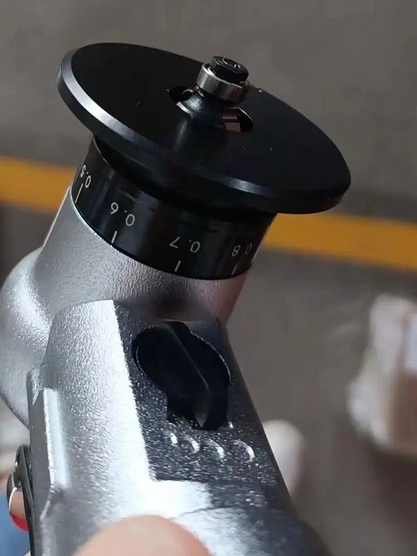
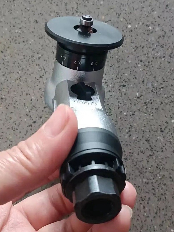
- Handheld Chamfering Tools: Irregular edges, on-site repair – Portable and flexible; ideal for small batches and variable shapes
- Pipe Chamfering Machines: Steel and stainless-steel pipes – Designed for pipe ends; inner, outer, and face chamfering in a single pass
- Double-Head Chamfering Machines: Rod and tube ends – Simultaneous double-end processing; high efficiency and precision; ideal for automated lines (e.g., servo-driven models)
7.2CNC Chamfering Tools (For Lathe/Mill/CNC Use)
- Chamfer Inserts: CNC lathes – Mounted on tool holders; suited for continuous, repeatable chamfering
- Chamfer End Mills: CNC machining centers – Common angles: 30° / 45° / 60°; ideal for edge and hole chamfering
- Center Drills: Hole positioning with chamfering – Pilot hole and chamfer completed in one step
- Combination Chamfer Tools: Inner and outer edge integration – Efficient for compound processes like chamfering, deburring, and edge rounding in one operation
7.3Manual & Lightweight Chamfering Tools (For Repair & Edge Finishing)
- Deburring Tools: Inner holes, sharp edges – Hand-operated; compact and easy to use; suitable for localized finishing
- Manual Chamfer Knives: Edges, hole entrances – Quick and simple operation; ideal for soft metals or light-duty work
- Files / Grinding Wheels / Sandpaper: Various edge geometries – Low-cost, flexible handling; useful for manual edge finishing and surface smoothing
7.4Chamfering Attachments for Laser / Plasma / Waterjet Cutting
These are integrated into automated systems for edge transitions and bevel preparation:
- Laser Cutting Head with Angle Control Module: Suitable for 45° bevels
- Plasma Bevel Cutting Head: Designed for high-speed beveling during cutting
- Multi-Axis Waterjet Tilt Heads: Allow precise edge chamfering via angular control
7.5Recommended Accessories & Tool Pairings
For Angle Grinder Users: Flap Discs are highly recommended
Curved flap discs for inner corners; straight flap discs for flat edges
For non-ferrous metals, use abrasive cloth with a coolant additive to reduce thermal discoloration and corrosion
For Die Grinder / Pneumatic Grinder Users: Use Carbide Burrs
Construction: Tungsten carbide cutting head + tool steel shank
Tooth Profiles:
- Z6 Cross Cut: High material removal rate; suitable for rapid processing
- Z3 Single Cut: Produces smoother surface finish
- Shipbuilding Profile: Optimized for heavy-duty tasks; approx. 30% higher removal rate
8.0Tool Selection Guide (By Application Scenario)
Application Need: Recommended Tool Type
- Pipe End Preparation: Pipe Chamfering Machine, Double-Head Chamfering Machine
- CNC Machined Parts: Chamfer End Mills, Chamfer Inserts
- Irregular Edges / On-Site Repairs: Handheld Chamfering Tools, Manual Chamfer Knives
- Automated High-Volume Lines: CNC Tooling Systems, Servo-Driven Chamfering Machines
- Beveling for Welding Prep: Laser or Plasma Bevel Cutting Systems
9.0What Is a Chamfered Edge in CAD?
In CAD (Computer-Aided Design), a chamfer refers to the creation of an angled transition surface between two intersecting faces, replacing the original sharp edge. This design element not only simulates real-world manufacturing details but also provides functional benefits:
- Improved Assemblability: Chamfered edges help guide mating parts, enhancing assembly accuracy and efficiency.
- Enhanced Structural Performance: Reduces stress concentration caused by sharp corners, increasing overall part strength.
- Better Appearance & Manufacturability: Represents machining features for clearer process planning and downstream operations.
Most mainstream CAD software (such as AutoCAD, SolidWorks, and Fusion 360) supports several chamfer definition methods:
- Equal Distance Chamfer: Applies the same offset to both adjoining faces (commonly known as a C-type chamfer).
- Distance and Angle Combination: Defines a specific edge length and corresponding angle.
- Asymmetric Chamfer: Assigns different distances to each adjacent face.
Chamfers are typically defined during the early stages of 3D modeling and are automatically represented in 2D technical drawings to aid manufacturing and inspection.
10.0How to Create Chamfers in CAD
10.1Method 1: Equal Distance Chamfer (Symmetric)
Used to apply the same chamfer distance to both adjoining edges—commonly used for standard C-type chamfers.
Steps:
- Select the Chamfer tool from the “Modify” or “Features” menu.
- Select the edge or corner where the chamfer will be applied.
- Enter a uniform distance (e.g., 2 mm).
- Confirm and apply the chamfer.
10.2Method 2: Distance and Angle Chamfer
Ideal for features requiring a specific guiding angle, such as pin inserts or lead-ins for holes.
Steps:
- Activate the Chamfer
- Select the target edge.
- Set the linear distance (e.g., 3 mm) and desired angle (e.g., 45°).
- The software will automatically create the angled surface—confirm to apply.
10.3Method 3: Two-Distance Chamfer (Asymmetric)
Used for non-symmetric assemblies or space-constrained areas by assigning different chamfer lengths to each face.
Steps:
- Launch the Chamfer tool and select the target edge.
- Set two different distances for the adjoining faces (e.g., Side A: 5 mm, Side B: 2 mm).
- Confirm to generate the asymmetric chamfer.
11.0Chamfer vs. Break Edge
Break Edge refers to a very small chamfer—typically ranging from 0.01 mm to 0.5 mm—applied to remove sharp corners for safety and handling ease. It is considered a non-critical, functional feature and is commonly indicated in technical drawings with notes such as:
“Break all sharp edges.”
“Remove burrs and sharp corners”
Characteristics:
Dimensional accuracy is not strictly required
Typically performed manually or via automated deburring; considered a process convention
Chamfer, in contrast, is a precisely defined design feature with controlled dimensions and angles. Its functions go beyond edge softening and include:
- Assembly guidance
- Stress concentration reduction
- Aesthetic enhancement
- Accurate fit or alignment
Chamfers are usually specified within CAD models and clearly annotated in technical drawings (e.g., C1.0 × 45°), treated as intentional and controlled geometric elements.
12.0Chamfer vs. Countersink
Although both involve sloped surfaces, their functions and design intents differ significantly:
| Category | Chamfer | Countersink |
| Function | Edge breaking, assembly guidance, alignment, and aesthetics | Mounting flat-head screws flush with surface |
| Location | Any edge (inner or outer) | Inside holes |
| Geometry | Simple angled face | Conical recess, typically concentric |
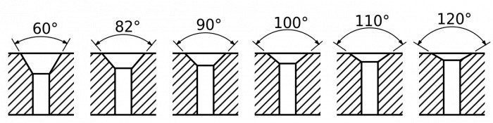
| Common Angles | 30°, 45°, 60° (customizable) | 82°, 90° (standardized) |
| Typical Callout | C1.0 × 45° | Countersink Ø8 × 90° |
| Screw Fitment | May assist insertion but not screw-specific | Matches standard flat-head screw specifications |
Summary: Countersinks are standardized and purpose-built for fasteners, while chamfers serve broader purposes and offer greater design flexibility.
13.0Chamfer vs. Deburring
Both processes improve edge quality, but they differ in intent, method, and control:
| Category | Chamfer | Deburring |
| Definition | A precisely dimensioned angled cut | Edge refinement by removing burrs |
| Control | Defined in CAD, strictly dimensioned | Often without specified size; process-driven |
| Method | Turning, milling, CNC machining | Grinding, brushing, manual filing, vibration, etc. |
| Purpose | Functional or structural feature | Safety and surface finish improvement |
| Form | Fixed angle and depth | Irregular, rounded, or micro-chamfered |
Summary: Chamfering is design-oriented and dimensionally controlled, while deburring focuses on safety and surface cleanliness. The two can be applied separately or in combination depending on functional and manufacturing needs.
14.0What Is a Chamfer in Engineering?
In engineering, a chamfer is a precisely machined angled surface applied to replace a sharp edge on a part. Unless otherwise specified, the standard chamfer angle is typically 45°.
Primary Functions of Chamfers:
- Eliminating Sharp Corners: Reduces stress concentration points and enhances structural integrity.
- Assembly Aid: Guides fasteners into holes or facilitates part alignment during assembly.
- Safety Improvement: Minimizes the risk of cuts, impact damage, or handling-related injuries.
- Interface Optimization: Improves the quality of welds, adhesive bonding, or bolted joints by smoothing contact surfaces.
In technical drawings, chamfers must be dimensioned and toleranced according to international engineering standards to ensure manufacturability and inspection consistency. Common standards include:
- ASME Y14.5
- ISO 13715
These standards are critical to achieving repeatability and reliability in precision mechanical design.
References
violintec.com/sheet-metal-and-stamped-parts/chamfers-vs-radii-in-sheet-metal-fabrication-know-the-difference/
https://en.wikipedia.org/wiki/Chamfer