- 1.0What Is a Chamfer?
- 2.0What Is a Bevel?
- 3.0Chamfer vs. Bevel: Key Differences
- 4.0Measuring Chamfers and Bevels
- 5.0Pipe Beveling vs. Pipe Chamfering: What’s the Difference?
- 6.0Why Is High-Precision Chamfering So Important?
- 7.0What Are the Benefits of Chamfering Components?
- 8.0What Are the Benefits of Beveling Components?
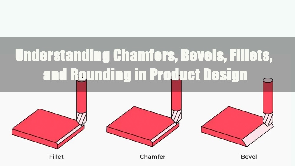
In metalworking, plastics processing, and machining, sharp 90° edges are not only prone to part damage but also pose safety risks. To eliminate these sharp corners, two common techniques are used during manufacturing: chamfering and beveling.
Although the terms “chamfer” and “bevel” are often used interchangeably, they differ significantly in geometry, machining method, and intended function.
This article provides a detailed comparison between chamfers and bevels, focusing on their geometric characteristics, machining techniques, and respective benefits.
1.0What Is a Chamfer?
The term chamfer originates from the Middle French word chamfrein, meaning “beveled edge.” In the fields of machining and manufacturing, it refers to a transitional edge created by cutting between two surfaces of a part. A related term, lark’s tongue, is occasionally used to describe special curved chamfer profiles.
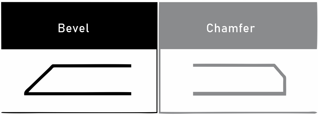
A chamfer is a sloped cut made between two adjoining surfaces of a workpiece, typically at a 90° corner. The most common chamfer angle is 45°, although this can be adjusted based on design specifications. Unlike a bevel, a chamfer does not extend through the full thickness of the material; it removes only a small portion at the edge to eliminate sharp corners, enhance visual appeal, or facilitate assembly.
Geometric Features of Chamfers:
- Fixed angle: Usually set at 45°, producing a symmetrical and consistent edge.
- Shallow depth: Only modifies the outer edge without affecting the part’s structural integrity.
- Straight-edge transition: Unlike a fillet’s curved profile or a bevel’s extended slope, chamfers form flat, angled edges.
Common Chamfering Methods:
Typical chamfering tools include:
- Chamfer mills: High-precision cutters used on CNC milling machines.
- Hand scrapers or chamfering knives: Manual tools suitable for small batches or on-site edge finishing.
- Rotary deburring tools or grinding wheels: Used for irregular edges or when a high surface finish is required.
Chamfering Equipment:
- CNC chamfering machines
- Handheld manual chamfering tools
- Double-head chamfering machines
- Rotary chamfer mills / deburring chamfering tools
- Pipe chamfering machines / tube-end chamfering systems
Applications of Chamfering:
- Metal CNC machining: Commonly used on edges of mechanical components, gears, and threaded sections.
- Plastic and glass products: Improves edge smoothness and surface appearance.
- Architectural and home finishes: Applied to table or countertop edges for safety and aesthetics.
2.0What Is a Bevel?
A bevel refers to an angled surface that connects two non-perpendicular or parallel surfaces. Like a chamfer, a bevel is used to remove sharp edges, but it differs in both angle and scope. Bevels typically involve a larger cut area and may extend through part or all of the material’s thickness.
Geometric Features of Bevels:
- Flexible angles: Bevel angles can vary based on structural or functional requirements—common angles include 15°, 30°, and 45°.
- Larger cut area: A bevel often runs along the full edge length and removes more material than a chamfer.
- Sloped transition: Unlike the flat, precisely angled surface of a chamfer, a bevel creates a more gradual, functional slope.
Typical Applications of Beveling:
- Structural welding: Preparation of plate edges or pipe ends for weld joints (e.g., bevel grooves).
- Automotive parts: Beveled gears and inclined sealing surfaces.
- Furniture and construction materials: Decorative bevels on picture frames, mirrors, and cabinet edges.
- Consumer electronics: Sloped bezels and beveled optical window finishes.
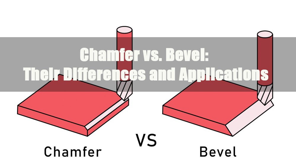
3.0Chamfer vs. Bevel: Key Differences
Definition and Context:
- Bevel: A bevel generally refers to an angled edge that connects two parallel surfaces. This angled surface is not always the result of cutting—it can also be formed during the material’s original shaping process. Bevels may occur naturally during manufacturing or be intentionally introduced.
- Chamfer: A chamfer specifically refers to an angled edge created by cutting. It typically occurs between two adjoining surfaces and always involves material removal.
In summary:
- A bevel does not necessarily require cutting, whereas a chamfer always involves a cutting process.
- Chamfers are applied between adjacent surfaces, while bevels are more commonly found as transitions between parallel surfaces.
Geometric Differences:
Chamfers and bevels also differ in their geometric characteristics:
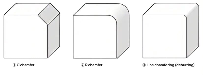
- Chamfer: Typically cut at a 45° angle and used to connect two adjoining surfaces. For example, chamfering each corner of a square workpiece will result in an internal geometry that closely resembles an octagon.
- Bevel: While 45° is also common, the angle can be freely adjusted depending on the design. Bevels are suited for connecting parallel surfaces or creating sloped transitions. A fully beveled prismatic part may have a cross-section shaped like a rhombus or other slanted profile.
Machining Differences:
Chamfers and bevels are produced using different tools and methods:
Chamfering:
- Performed on a milling machine using a chamfer end mill.
- For cylindrical parts, chamfering can be done on a lathe using rotary broaching.
- In CNC machining, chamfers can be produced with multiple passes, though this increases cycle time.
Beveling:
- Performed using beveling machines or specialized tools.
- Plate beveling machines: Used for flat sheet or plate materials.
- Pipe beveling machines: Commonly used to prepare pipe ends for welding.
- In some cases, chamfering tools may be used to create bevels, requiring multiple cutting passes to achieve the desired angle.
4.0Measuring Chamfers and Bevels
4.1General Measurement Tools
(1) Optical Comparator:
Equipped with high-magnification lenses and a projection system to enlarge edge profiles for analysis.
Supports manual measurements and digital readouts, suitable for high-precision inspections.
Commonly used in quality control for mass production.
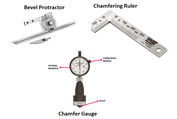
(2) Chamfer Gauge:
Uses a spring-loaded plunger that contacts the angled surface to measure leg length or chamfer depth.
Available in analog, digital, and CNC-compatible models
Suitable for quick inspection of both chamfers and bevels.
4.2Specialized Measurement Tools
(1) Bevel Protractor:
Consists of a rotating blade assembly with a circular angle scale.
Measurement method:
One blade aligns with the bevel surface, the other with a reference plane.
The included angle represents the bevel angle.
Advantage: Capable of measuring fine angular deviations, ideal for weld grooves and beveled gear surfaces.
(2) Chamfer Ruler:
L-shaped device made from two graduated stainless steel scales positioned along the vertical and horizontal surfaces of a part.
Measures the two leg lengths to calculate the chamfer face length and angle.
Suitable for manual inspection and drawing verification.
4.3Angle and Dimension Conversion Example
If a chamfer ruler measures:
Horizontal leg = 3 mm
Vertical leg = 3 mm
Then the chamfer angle is 45°, and the chamfer length (hypotenuse) is approximately 4.24 mm (by the Pythagorean theorem).
Summary Table:
| Tool Type | Best For | Advantages | Typical Applications |
| Optical Comparator | Chamfers & Bevels | High-precision visual inspection | CNC part inspection, lab measurement |
| Chamfer Gauge | Chamfers | Fast measurement, simple design | Automated chamfer quality control |
| Bevel Protractor | Bevels | Measures fine angles | Weld grooves, structural bevel inspection |
| Chamfer Ruler | Chamfers | Low cost, wide applicability | On-site manual measurement in workshops |
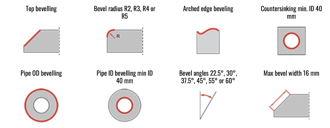
5.0Pipe Beveling vs. Pipe Chamfering: What’s the Difference?
| Category | Bevel Cutting | Chamfering |
| Definition | Cutting the pipe end at a specific angle (e.g., 45°), typically for welding prep | Removing sharp edges from the inner and outer pipe edges for better fit and safety |
| Target Area | Pipe end face or outer wall | Inner and outer edges of the pipe |
| Applications | Butt welding, structural joints, groove preparation | Assembly alignment, deburring, reducing stress concentration |
| Typical Shapes | Deep bevels, J-grooves, U-grooves | V-type chamfers, rounded edges (R), tapered transitions |
| Precision Requirement | High (especially to ensure weld penetration and angle consistency) | Medium to high (especially for sealing or precision assemblies) |
6.0Why Is High-Precision Chamfering So Important?
In industries such as aerospace, automotive, and pharmaceutical manufacturing, pipe-end chamfers must meet strict specifications for angle and depth. Even minor deviations—on the order of thousandths of an inch—can lead to:
- Oversized assembly gaps or improper fit
- Seal failure and leakage
- Increased stress concentration, leading to fatigue failure
- Non-compliance with validation standards (e.g., FDA, ISO, AS9100)
As a result, customers often require machines with CpK capability (Process Capability Index) to ensure consistent, within-tolerance production across all parts.
Automated High-Precision Chamfering: Servo-Driven Pipe Chamfering Machines
To meet the demand for consistent and precise chamfering in high-end sectors, fully automated servo-controlled pipe chamfering machines have been developed. Key advantages include:
- Servo control system: Enables accurate control of feed angle and cutting depth, ensuring high repeatability.
- Rigid machine frame: Provides stability and minimizes vibration during operation.
- Automated feeding and clamping: Supports multi-batch continuous processing with minimal manual intervention.
- Smart process settings: Allows rapid changeover between different pipe sizes and angles, improving production flexibility.
These machines are suitable for chamfering a wide range of metals—including stainless steel, carbon steel, and alloy pipes—and can perform multi-angle and multi-step chamfering, making them essential for achieving high-efficiency and high-consistency results.
7.0What Are the Benefits of Chamfering Components?
- Enhanced safety: Chamfering removes sharp edges from parts, reducing the risk of cuts, abrasions, or clothing snags during handling. It is commonly applied to furniture edges and handheld parts to improve user safety.
- Easier assembly and disassembly: Chamfers facilitate the insertion of fasteners such as bolts and nuts, preventing edge chipping and increasing fit precision and connection strength.
- Improved aesthetics and perceived quality: Chamfers soften harsh corners and give components a more refined and polished outline, enhancing overall product design—widely used in woodworking, jewelry, and high-end equipment.
- Better alignment during assembly: Chamfers help guide parts into mating holes, reducing misalignment and assembly errors, and improving installation efficiency and accuracy.
- Reduced friction and increased wear resistance: A chamfered edge creates a smooth transition that minimizes friction between sliding surfaces. For example, chamfered brake pads can reduce noise and vibration during operation.
- Improved manufacturability and lower production costs: Incorporating chamfers in the design phase can eliminate the need for secondary finishing operations. When paired with molding tools or form cutters, chamfers can simplify processing steps and reduce manufacturing expenses.
8.0What Are the Benefits of Beveling Components?
- Enhanced safety: Bevels soften 90° corners, reducing impact-related injuries. Common in structural edges, though one side of the bevel may still form a sharp point if not properly managed.
- Easier assembly and disassembly: Beveled edges help large panels, boards, or metal structures mate more smoothly, supporting more secure and efficient assembly.
- Improved aesthetics and product definition: Bevels add geometric definition to components, increasing visual depth and design precision—frequently seen in device housings, architectural elements, and decorative finishes.
- Improved alignment performance: By adjusting bevel angles, components can naturally align and interface more accurately, which is particularly valuable in frame systems and complex assemblies.
- Reduced friction and enhanced wear performance: Bevels can improve contact surface geometry, reducing friction and material wear. For instance, in gear engagement or sliding mechanisms, bevels contribute to smoother motion.
- Improved manufacturability and structural adaptability: Bevels are ideal for groove welding and structural transitions. With the use of beveling machines, these edges can be formed in a single pass—speeding up production and improving efficiency.
References
www.madearia.com/blog/chamfer-vs-bevel/
www.colstanprofiles.co.uk/chamfer-vs-bevel-key-differences-applications-and-benefits/