This document applies to fastening operations across multiple sectors, including mechanical manufacturing, construction engineering, and equipment assembly. It outlines five core tightening methods—torque wrench method, turn-of-nut method, hydraulic tensioner method, direct tension indicator (DTI) washer method, and bolt elongation method.
Designed as both a practical guide and a technical reference, this document serves as a foundational resource for on-site operations, personnel training, and quality control management. It ensures that every tightening process meets consistent standards of accuracy, safety, and reliability, supporting optimal performance and long-term integrity in all fastening applications.
1.0Terminology and Definitions
- Proof Load: The maximum tensile load a fastener can withstand without incurring permanent deformation.
- Clamping Load: The compressive force exerted on the joint after tightening; it should be adjusted according to the specific type of connection.
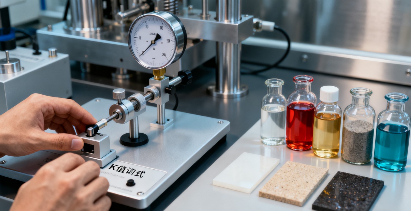
- Nut Factor (K Value): An empirical coefficient that accounts for thread and bearing surface friction; a critical parameter in torque calculations.
- Elastic Recovery Loss: In hydraulic tensioning operations, this refers to the ratio between the final tensile force on the nut and the initial applied load. A compensation allowance must be considered in advance.
- Preload: The internal tensile stress generated within a bolt after tightening; it is a key indicator for maintaining joint stability.
- Strain: The degree of deformation a fastener undergoes under tensile stress, directly proportional to the applied stress (within the elastic limit).
2.0General Preparations
2.1Personnel Qualification and Training Requirements
| Operation Type |
Qualification Requirements |
Key Training Topics |
| Standard Operations |
Basic training completed; familiar with standard procedures and safety protocols |
Principles of tightening methods, basic tool operation, quality evaluation criteria |
| Critical Operations |
Certified personnel with parameter adjustment and troubleshooting capability |
Torque/load calculation, equipment calibration, handling of special conditions, emergency procedures |
2.2Equipment and Tool Inspection
| Equipment Type |
Inspection Items |
Standard Requirements |
Calibration / Maintenance Interval |
| Tightening Tools (e.g., torque wrench, hydraulic tensioner) |
Appearance, accuracy, operating condition |
No damage or corrosion; deviation ≤ ±2%; no abnormal noise during operation |
Every 6 months |
| Measuring Instruments (e.g., feeler gauge, dial indicator) |
Cleanliness, precision |
No oil or debris; accuracy meets operation standards (feeler gauge ≥0.01 mm, dial indicator ≥0.001 mm) |
Calibrate every 3 months |
| Auxiliary Materials (e.g., lubricants, safety gear) |
Model compatibility, expiration status |
Lubricants suitable for conditions and within shelf life; protective gear intact and safety compliant |
Inspect before each use |
2.3Environmental and Material Preparation
| Category |
Specific Requirements |
| Environmental Conditions |
Clean and free of dust or oil; humidity ≤60%; temperature 5°C–35°C. For outdoor operations, apply rain and wind protection. In low-temperature conditions, preheat lubricants. |
| Material Inspection |
Ensure fasteners match design specifications in size and material; no thread damage or corrosion. Mating surfaces must be clean and flat. |
| Pre-Treatment |
Clean threads and contact surfaces, remove oil and rust; apply lubricant evenly without excess accumulation. For custom or high-precision applications, use a thread rolling machine to refine thread quality before pre-treatment, reducing friction variations during subsequent tightening. |
3.0Standardized Operating Procedures by Method (Tabular Format)
3.1Torque Wrench Method
| Process Stage |
Operation Step |
Operational Requirements |
Tools & Equipment |
Key Parameters |
Common Issues & Solutions |
| Preliminary Calculation |
Determine Proof Load |
Use the specified value; if not indicated, calculate as 92% of yield strength |
Calculator, Material Data Sheet |
– |
Yield strength unknown: request a test report from the technical department |
|
Set Clamping Load |
For reusable joints: Proof Load × 75%; for permanent joints: Proof Load × 90% |
Calculator |
Clamping load deviation ≤ ±3% |
Special conditions: adjust based on technical instructions |
|
Select and Calibrate K Value |
Choose per standard; conduct lab calibration for high-precision cases |
Torque calibrator |
See Table 1 “Reference K Factor” |
Deviation found: re-test friction coefficient |
|
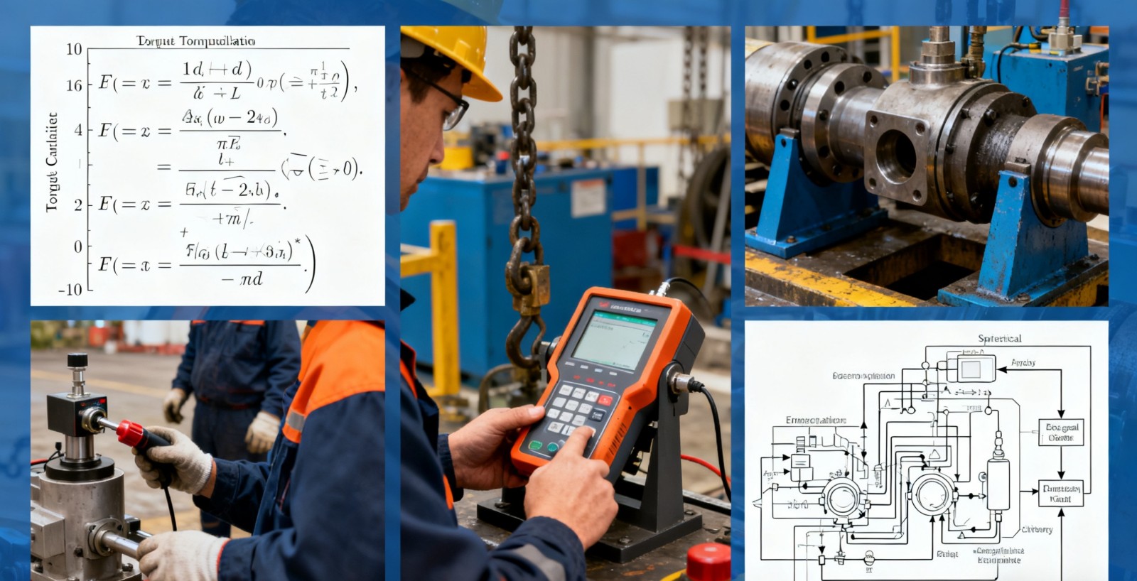
Calculate Target Torque |
Apply formula T = KDP (T = torque, D = nominal diameter, P = clamping load) |
Calculator |
Torque accuracy to two decimals |
Calculation error: double-check results by two operators |
| On-Site Operation |
Cleaning & Lubrication |
Threads and contact surfaces clean, evenly lubricated |
Brush, cloth, lubricant |
– |
Excess lubricant: wipe off excess to maintain friction accuracy |
|
Manual Preload |
Hand-tighten fastener until snug, no binding |
Gloves |
– |
Binding threads: inspect for damage and replace fastener |
|
Set Torque Wrench |
Adjust to target torque, ensure calibration is valid |
Calibrated torque wrench |
Torque deviation ≤ ±2% |
Tool fault: replace and send for repair |
|
Final Tightening |
Keep wrench perpendicular to bolt axis; apply steady, uniform force |
Torque wrench |
Rotation speed ≤ 5 r/min |
Torque off-spec: recheck friction or thread condition |
|
Verification |
Recheck after 5 minutes using same calibrated wrench |
Torque wrench |
Retest deviation ≤ ±5% |
Deviation too high: retighten and document cause |
3.2Turn-of-Nut Method
| Process Stage |
Operation Step |
Operational Requirements |
Tools & Equipment |
Key Parameters |
Common Issues & Solutions |
| Preparation |
Verify Thread Pitch |
Determine thread pitch and calculate rotation angle (360° = one thread pitch elongation) |
Thread gauge, calculator |
Pitch tolerance ≤ ±0.01 mm |
Pitch unknown: check fastener datasheet |
|
Check Joint Fit |
Ensure mating surfaces are clean and properly seated |
Feeler gauge |
Initial gap ≤ 0.02 mm |
Gap too large: clean or reposition joint components |
| On-Site Operation |
Manual Preload |
For structural component mass production: use a fastener insertion machine to achieve uniform pre-positioning of bolts/nuts, ensuring consistent gap elimination. For small-batch: hand-tighten until surfaces are snug. |
Gloves |
– |
Loose fit: continue tightening until no play |
|
Mark Reference Line |
Mark alignment line on nut and bolt |
Marker |
Clear, visible marks |
Faint mark: remark to ensure angle accuracy |
|
Controlled Rotation |
Rotate nut slowly to the specified angle with even force |
Angle-marked wrench |
Angle deviation ≤ ±2° |
Hard turning: inspect for thread binding |
|
Fit Verification |
Recheck markings and joint gap |
Feeler gauge |
No visible gap |
Residual gap: tighten further and record extra angle |
3.3Hydraulic Tensioner Method
| Process Stage |
Operation Step |
Operational Requirements |
Tools & Equipment |
Key Parameters |
Common Issues & Solutions |
| Preliminary Calculation |
Set Target Load |
Determine clamping load per joint design; allow for elastic recovery |
Calculator |
Initial load = Target × 1.25–1.30 |
Uncertain load: use 80% of proof load as reference |
|
Inspect Equipment |
Ensure inserts, seals, and pressure display are in good condition |
Hydraulic tensioner, pump |
Pressure deviation ≤ ±1% |
Seal damaged: replace and retest |
| On-Site Operation |
Clean Threads |
Remove rust and debris from exposed threads |
Brush, cloth |
– |
Severe corrosion: clean or replace bolt |
|
Install Tensioner |
Insert depth ≥1.5× nut thickness; base flush and level |
Hydraulic tensioner, wrench |
– |
Base misaligned: use shims to correct verticality |
|
Apply Pressure |
Increase pressure gradually to initial target; hold for 3–5 minutes |
Pump, gauge |
Pressure rise ≤ 0.5 MPa/s |
Pressure drop: check leaks before retrying |
|
Tighten Nut |
While under pressure, tighten nut until seated |
Wrench |
Nut secure, no offset |
Nut jams: use coarse-thread alternative |
|
Pressure Release & Verification |
Release pressure gradually; remove tensioner and recheck torque |
Torque wrench |
Torque deviation ≤ ±5% |
Low preload: repeat with higher initial pressure |
3.4DTI Washer Method
| Process Stage |
Operation Step |
Operational Requirements |
Tools & Equipment |
Key Parameters |
Common Issues & Solutions |
| Preparation |
Match Washer Spec |
Select washer matching bolt size; ensure protrusions are intact |
Caliper, magnifier |
Dimensional deviation ≤ ±0.1 mm |
Deformed protrusions: replace washer |
|
Define Gap Range |
Confirm acceptable gap based on target preload |
Spec sheet, calculator |
As specified by washer manufacturer |
Unknown range: refer to historical data |
| On-Site Operation |
Position Washer |
Place washer under bolt head or nut, bumps facing up |
Gloves |
Proper alignment |
Off-center: reposition washer |
|
Initial Tightening |
Tighten to 80% of target torque |
Torque wrench |
– |
Resistance: inspect threads or washer surface |
|
Measure Gap |
Measure washer gap using feeler gauge |
Feeler gauge (0.01 mm accuracy) |
Within preset range |
Gap too wide: continue tightening |
|
Final Confirmation |
Record final gap and confirm uniform compression |
Log sheet, feeler gauge |
Gap deviation ≤ ±0.02 mm |
Uneven gap: correct bolt alignment |
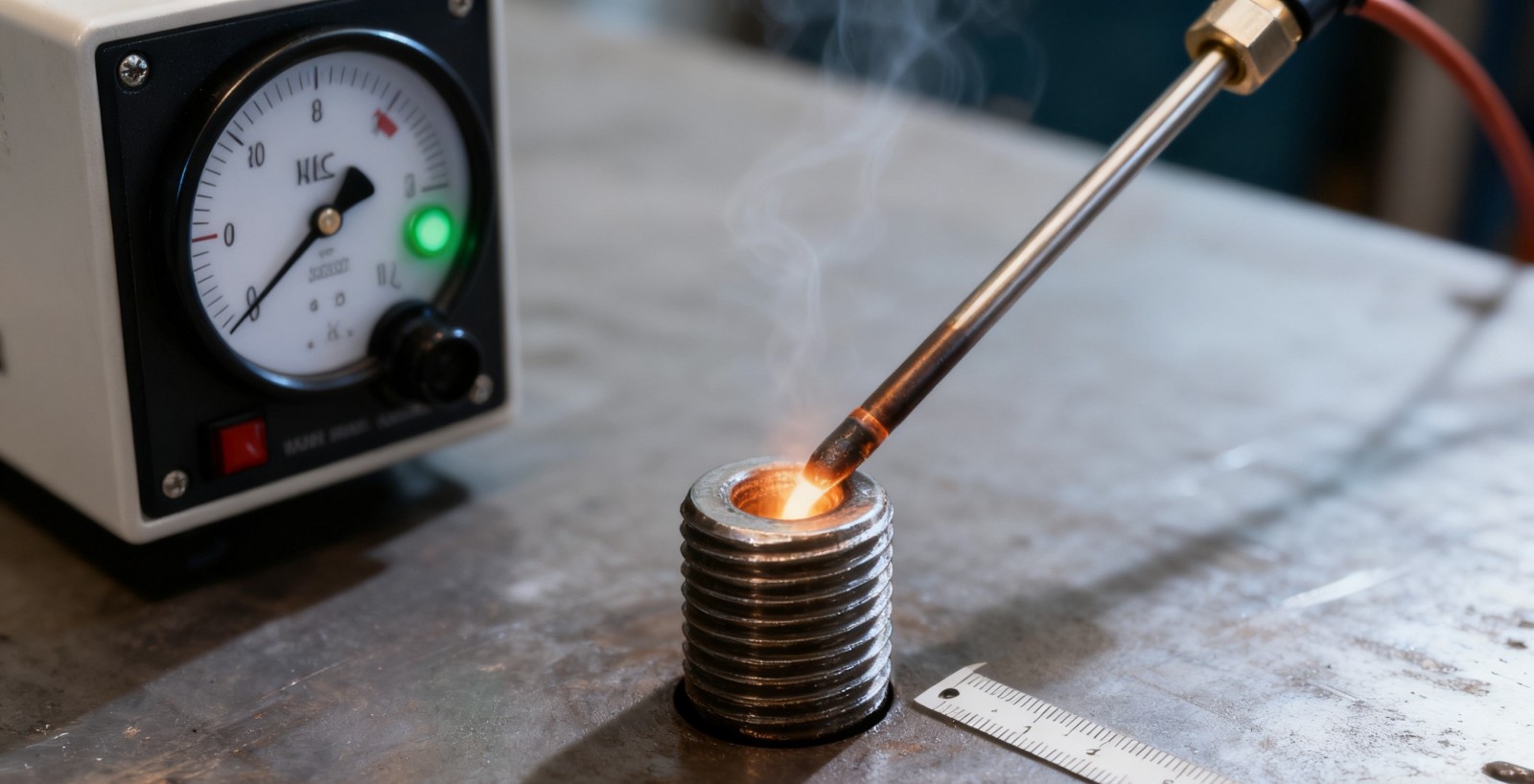
3.5Bolt Elongation Method (Including Hydraulic, Thermal, and Precision Measurement Techniques)
This method determines tightening accuracy by directly measuring bolt elongation, ensuring controlled preload through hydraulic tensioning, thermal expansion, or precision measurement.
Hydraulic Tensioning Process
| Process Branch |
Process Stage |
Operation Step |
Operational Requirements |
Tools & Equipment |
Key Parameters |
Common Issues & Solutions |
| Hydraulic Tensioning |
Preparation |
Calculate Stretching Parameters |
Target elongation = (Target stress × Bolt length) / Elastic modulus |
Calculator, Bolt specification sheet |
Elongation deviation ≤ ±3% |
Unknown parameters: contact technical department for material data |
|
|
Verify Compatibility |
Ensure tensioner matches bolt diameter |
Caliper, Tensioner |
Diameter tolerance ≤ ±1 mm |
Mismatch: replace with correct-size tensioner |
|
On-Site Operation |
Install Tensioner |
Insert depth sufficient, base seated flat |
Tensioner, Wrench |
Depth ≥ 1.5 × nut thickness |
Loose seating: use shims for adjustment |
|
|
Apply Pressure and Measure |
Pressurize until target elongation is reached; monitor continuously |
Hydraulic pump, Dial indicator |
Pressure rise ≤ 0.5 MPa/s |
Insufficient elongation: increase pressure gradually |
|
|
Tighten and Depressurize |
While holding pressure, tighten nut fully and then release pressure slowly |
Wrench, Hydraulic pump |
Nut flush and secure |
Nut loosening: retighten and verify |
|
|
Final Measurement |
Measure actual elongation after unloading |
Dial indicator |
Deviation from target ≤ ±5% |
Deviation excessive: repeat process with adjusted settings |
Thermal Tightening Process
| Process Branch |
Process Stage |
Operation Step |
Operational Requirements |
Tools & Equipment |
Key Parameters |
Common Issues & Solutions |
| Thermal Method |
Preparation |
Determine Heating Parameters |
Calculate target elongation, define heating temperature and duration |
Calculator, Heater rod spec sheet |
Max temperature ≤ 80% of tempering temperature |
Overheating: may reduce material strength—stop heating immediately |
|
|
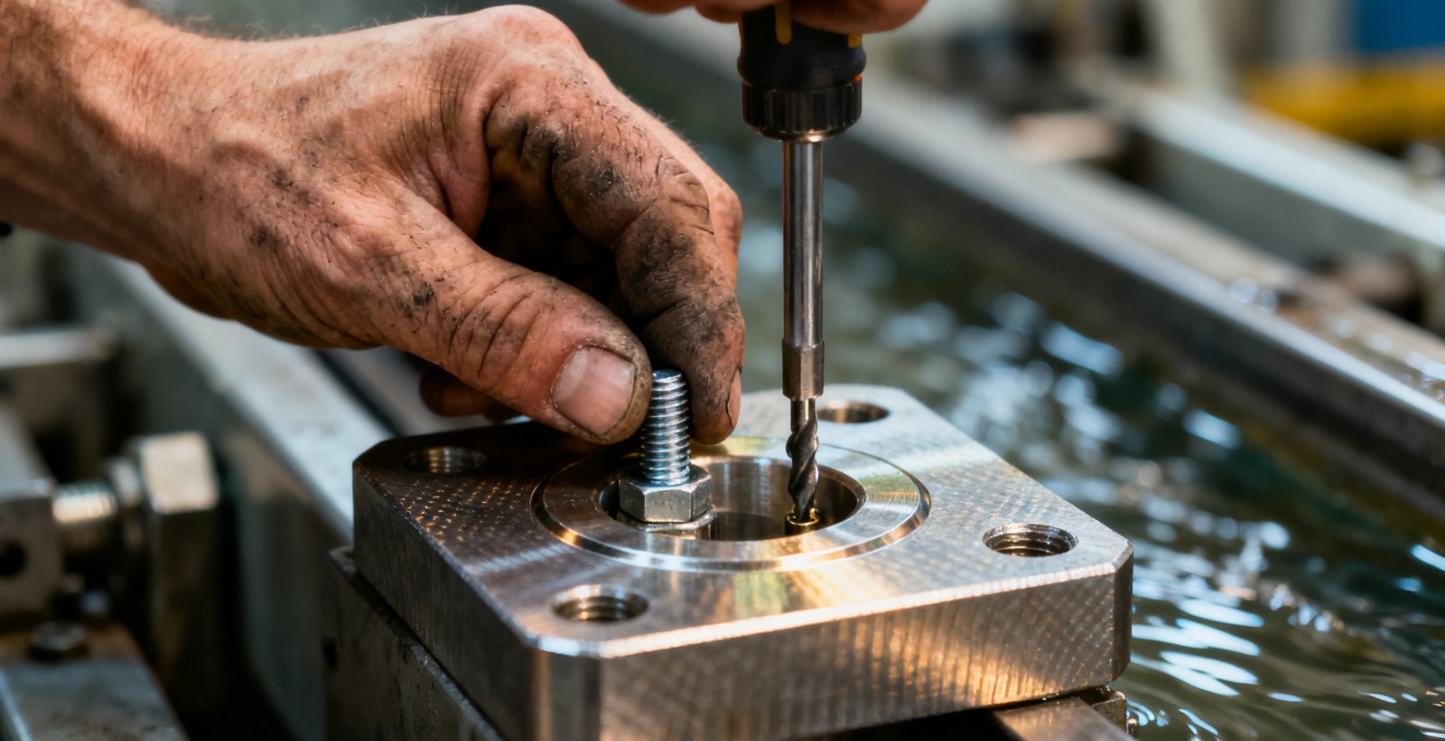
Inspect Central Hole |
Ensure bolt center hole is clear and burr-free |
Drill (if needed), Brush |
Hole size compatible with heater rod |
Hole undersized: enlarge to fit |
|
On-Site Operation |
Install Heater Rod |
Insert and secure heating element in center hole |
Heater rod, Clamp |
Gap ≤ 2 mm between rod and wall |
Loose fit: refit to ensure even heating |
|
|
Heat and Monitor Elongation |
Continuously heat while monitoring elongation in real time |
Heater rod, Dial indicator |
Temperature rise ≤ 5 °C/min |
Rapid elongation: reduce power immediately |
|
|
Tighten Nut |
Once target elongation reached, tighten nut promptly |
Wrench, Dial indicator |
Nut fully seated |
Slow operation: cooling causes shrinkage—reheat and repeat |
|
|
Cool and Reinspect |
Allow bolt to cool to room temperature, remeasure elongation |
Dial indicator |
Final deviation ≤ ±5% |
Deviation excessive: repeat heating and adjustment |
Precision Measurement Process
| Process Branch |
Process Stage |
Operation Step |
Operational Requirements |
Tools & Equipment |
Key Parameters |
Common Issues & Solutions |
| Precision Measurement |
Preparation |
Select Measurement Tool |
Choose dial gauge or ultrasonic elongation meter according to bolt size and access |
Dial gauge, Ultrasonic meter |
Measurement accuracy ≥ 0.001 mm |
Low precision: replace with certified tool |
|
|
Measure Initial Length |
Record bolt length before loading |
Measurement tool |
Measure 3 times, take average |
Inconsistent data: check tool setup and bolt end flatness |
|
On-Site Operation |
Preload and Apply Load |
Hand-tighten, then apply tensile force smoothly |
Wrench, Loading equipment |
Uniform loading without impact |
Impact loading: repeat measurement after stabilizing |
|
|
Measure Under Load |
Record length during tensioning |
Dial gauge / Ultrasonic meter |
Measure 3 times, take average |
Difficult reading: adjust tool position |
|
|
Calculate Elongation |
Elongation = Loaded length − Initial length |
Calculator |
Elongation meets target specification |
Below target: increase applied load incrementally |
|
|
Lock and Verify |
Tighten nut to secure, then remeasure for confirmation |
Wrench, Measurement tool |
Final deviation ≤ ±3% |
Nut loosening: retighten and recheck |
4.0Reference Tables for Key Parameters
4.1Reference Table for Nut Factor (K Value)
| Material Type |
Lubrication Condition |
K Value |
Typical Application |
| Steel |
Graphite grease / engine oil |
0.10 |
General mechanical assembly |
| Steel |
Molybdenum disulfide grease |
0.11 |
High-load, low-friction applications |
| Steel |
Factory-applied light machine oil |
0.15 |
Assembly of new components without additional lubrication |
| Steel |
Copper-based anti-seize compound |
0.13 |
Connections in high-temperature environments |
| Steel |
Unlubricated |
0.20 |
Temporary or low-precision assemblies |
| Hot-dip galvanized steel |
Unlubricated |
0.25 |
Outdoor corrosion-resistant joints |
| Coated fasteners |
Unlubricated |
0.15 |
General-purpose anti-corrosion applications |
| Stainless steel |
Unlubricated |
0.30 |
High corrosion-resistance requirements |
4.2Reference Table for Elastic Recovery Loss
| Bolt Length (mm) |
Elastic Recovery Loss Ratio |
Initial Stretching Coefficient |
Applicable Method |
| ≤ 100 |
28% – 30% |
1.30 |
Hydraulic Tensioner Method |
| 101 – 300 |
25% – 28% |
1.28 |
Hydraulic Tensioner Method |
| ≥ 301 |
22% – 25% |
1.25 |
Hydraulic Tensioner Method |
4.3Accuracy and Application Comparison of Tightening Methods
| Tightening Method |
Accuracy Range |
Typical Application |
Cost Level |
| Hand-feel Method |
±35% |
Non-critical, static joints with no vibration |
Low |
| Torque Wrench Method |
±25% |
Standard engineering joints, batch assembly |
Low to Medium |
| Turn-of-Nut Method |
±15% |
Structural bolting, high-precision applications |
Medium |
| DTI Washer Method |
±10% |
Steel structures, bridges, and construction joints |
Medium |
| Bolt Elongation Method |
±3% – ±5% |
Heavy machinery, critical connections |
Medium to High |
| Strain Gauge Method |
±1% |
Laboratory testing, high-end precision equipment |
High |
5.0Quality Inspection and Record Forms
5.1Fastener Tightening Quality Inspection Record Form
| No. |
Batch No. |
Fastener Spec (Model / Material) |
Tightening Method |
Target Parameter (Torque / Angle / Elongation) |
Measured Value |
Deviation Range |
Inspection Tool & ID |
Conformance |
Operator |
Inspection Date |
Remarks (Issues & Actions) |
|
|
|
|
|
|
|
|
|
|
|
|
|
|
|
|
|
|
|
|
|
|
|
|
|
|
|
|
|
|
|
|
|
|
|
|
|
|
|
|
|
|
|
|
|
|
|
|
|
|
|
|
|
|
|
|
|
|
|
|
5.2Equipment Calibration Record Form
| Equipment Name |
Model / Specification |
Equipment ID |
Calibration Date |
Calibration Agency |
Calibration Items |
Calibration Result (Deviation Range) |
Next Calibration Date |
Technician |
Remarks |
|
|
|
|
|
|
|
|
|
|
|
|
|
|
|
|
|
|
|
|
|
|
|
|
|
|
|
|
|
|
6.0Safety and Maintenance Guidelines
| Category |
Specific Requirements |
| Operational Safety |
1. Always wear protective gear such as safety goggles and gloves during operations. Never stand directly in line with the bolt end during hydraulic tensioning or heating procedures.2. For work at height, secure a safety harness and construct stable working platforms. Outdoor operations must comply with local weather advisories and safety alerts. |
| Equipment Maintenance |
1. Clean and service all tools after use. Release the spring tension on torque wrenches before storage, and ensure hydraulic systems are fully depressurized after operation.2. Inspect tools and equipment regularly for wear or damage; replace defective components immediately. Operating with faulty equipment is strictly prohibited. |
| Quality Traceability |
1. Retain all operational records and inspection data for a minimum of one year; retain records of critical processes for three years or more.2. In the event of batch non-conformance, halt operations immediately, investigate the root cause, and implement corrective actions. |
| Emergency Response |
1. In the event of equipment failure, cut power or release pressure immediately to prevent secondary injuries. Use dedicated fire extinguishers for any fire-related hazards.2. Establish an emergency communication protocol with designated responsible personnel and clearly defined response procedures. |
References
www.totem-forbes.com
www.waltontools.com