1.0Punching Techniques Guide
In modern manufacturing, punching technology serves as one of the core processes in metal forming and is widely applied in industries such as automotive, electronics, and home appliances. Different punching methods not only affect production efficiency but are also directly related to product quality and cost control.
This article provides an in-depth overview of nine key punching techniques, including blanking, round hole punching, small and large hole punching, and intermittent punching. It aims to help engineers and manufacturing professionals fully understand the characteristics and application points of each technique, thereby improving the precision and efficiency of punching operations.
2.0Blanking
In blanking, the traditionally discarded slug becomes the desired finished product. Recommendations are as follows:
- Confirm key dimensions and clearly specify the “blanking” purpose when ordering.
- Die size corresponds directly to the final part size; punch dimensions are calculated in reverse based on the die.
- Use sharp punches and dies to improve sidewall straightness.
- Reducing die clearance by approximately 5% can increase the proportion of the burnished area and enhance dimensional consistency.
- Use flat-faced punches.
- Use non-stripping dies.
- Since reduced clearance increases wear rate, tool wear should be inspected more frequently.
3.0Corner Rounding
4-Way Radius Tool
- Forms all four corners in one operation, replacing multiple processes or dedicated tools.
- Compatible with both single-station and multi-tool turret systems.
- Improves processing efficiency and reduces machine wear.
- Micro-joint designs can be implemented for easy part removal using a “shake-and-break” process.
- Example: For 100 parts, a 4-way tool requires only about 108 hits, reducing operations by approximately 75%.
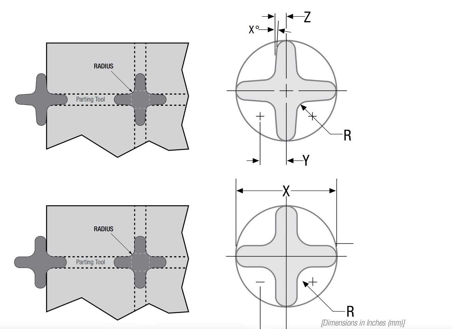
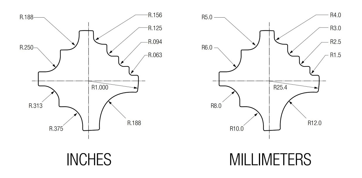
9-Way Corner Rounding Tool
- Offers nine common radius sizes (from 1/2″ to 1/16″).
- Automatically indexes to the corresponding radius.
- Use of fully guided tooling is recommended to enhance punch support.
- The radius design must cover at least a 90° arc.
- The minimum “nose” width between adjacent radii should be 0.188 inches (approximately 4.7 mm) to ensure tool strength.
4.0Small Diameter Holes
Recommended punch diameter-to-material thickness ratios:
| Material | Non-Guided Tooling Ratio | Fully Guided Tooling Ratio |
| Aluminum | 0.75:1 | 0.5:1 |
| Mild Steel | 1:1 | 0.75:1 |
| Stainless Steel | 2:1 | 1:1 |
Example: For 2.0 mm-thick stainless steel, the recommended minimum hole diameter is:
- Non-guided tool: 4.0 mm
- Fully guided tool: 2.0 mm
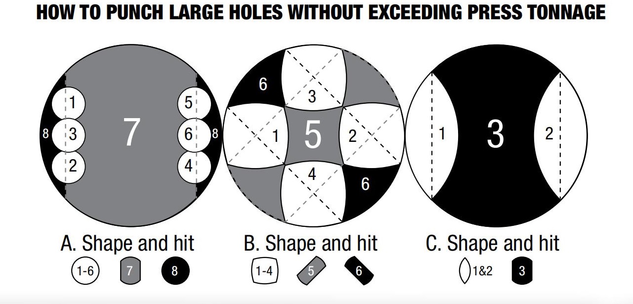
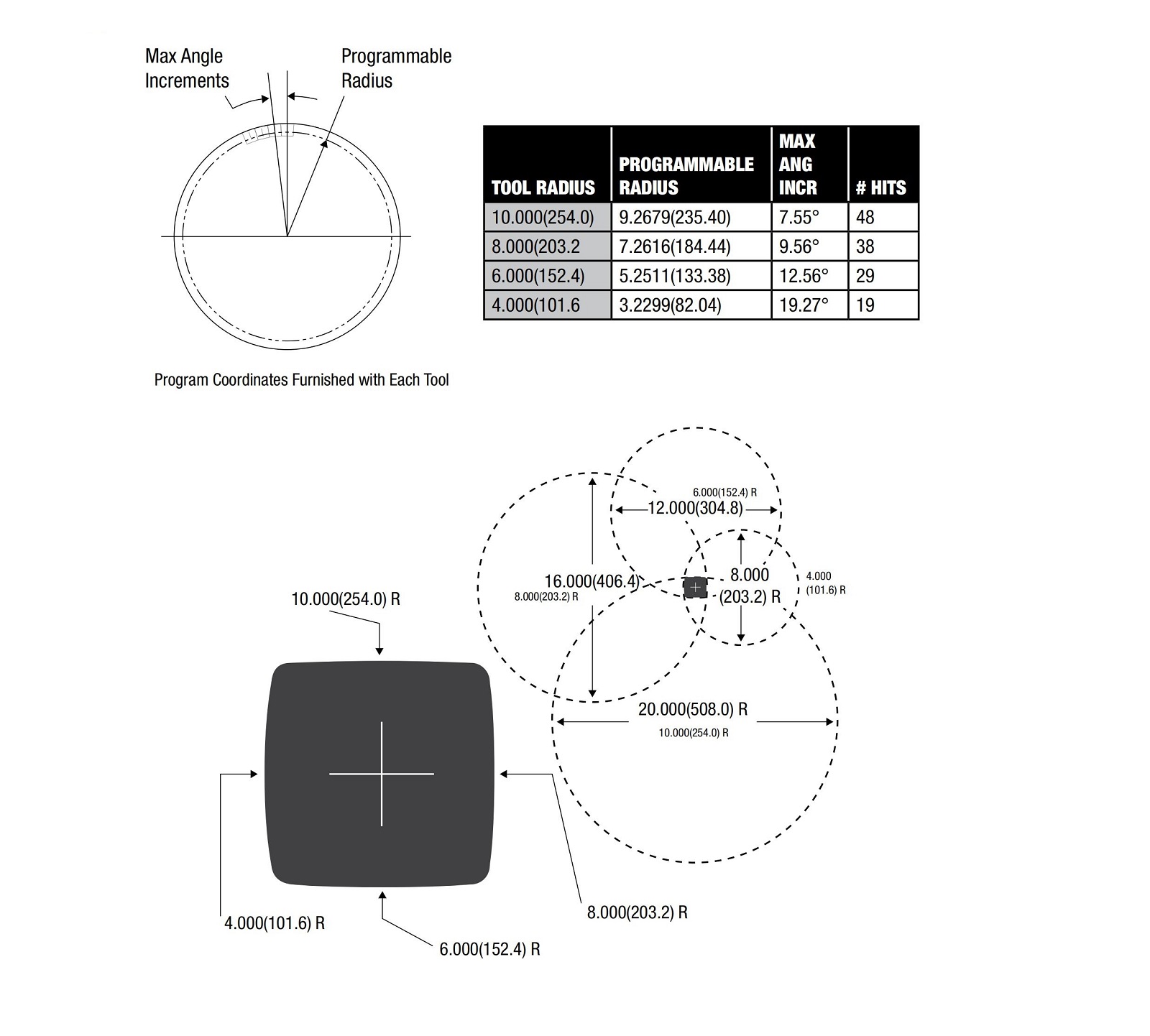
5.0Large Diameter Holes
Punching oversized holes in a single hit requires high force. It is recommended to use a segmented approach:
- Use smaller punches to segmentally punch out the hole contour, reducing punch force by over 50%.
- Punch shapes can be designed as double-D, four-radius, or double-lobe to achieve clean cuts and reduce tabletop residue.
6.0Nibbling
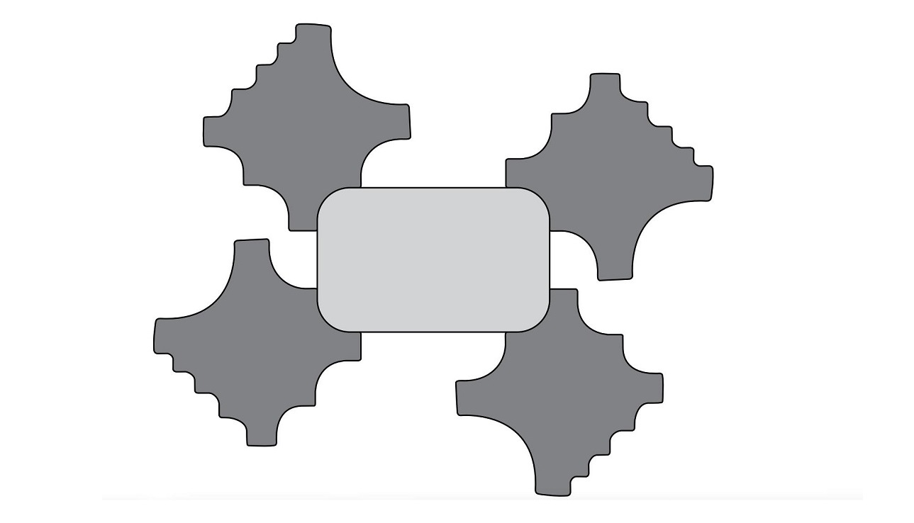
Quad Radius Tool
- Enables faster and smoother punching of large holes.
- Requires fewer hits; ideal for auto-index stations.
- Fully guided tooling is recommended to improve punch alignment and clamping force.
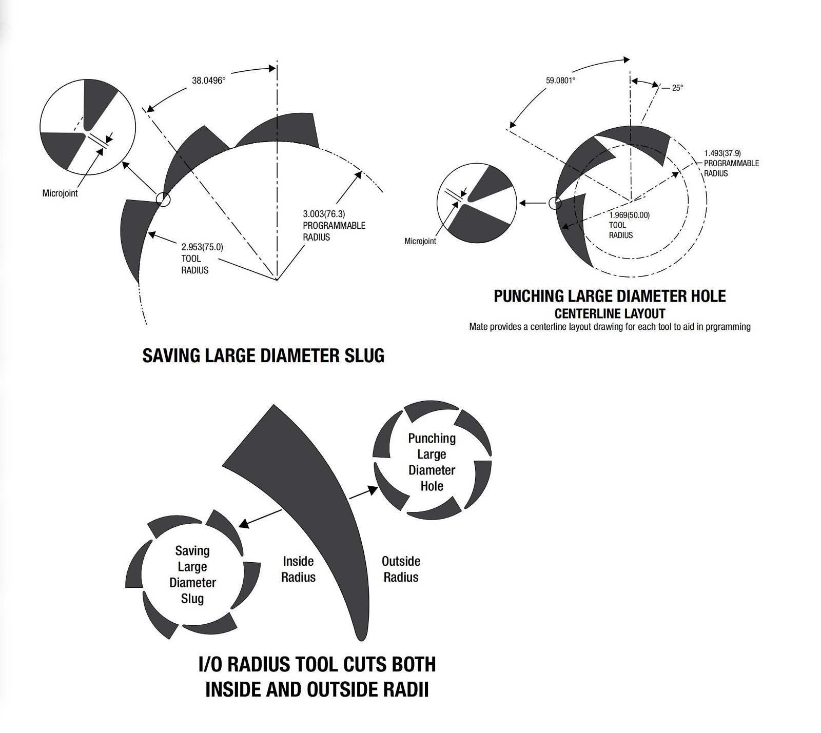
Inside/Outside Radius Tool
- Forms smooth edges while retaining the slug or blank within the material using micro-joints for easy subsequent separation.
- Micro-joint size should be adjusted based on material type and thickness.
7.0Slitting
- Slitting involves lateral loads, increasing the risk of punch deflection or material being pulled into the die.
- Using elliptical punches with rounded-corner dies is recommended to reduce “sawtooth” edges.
- This design is especially suitable for older punching machines, offering smoother edges and safer parts.
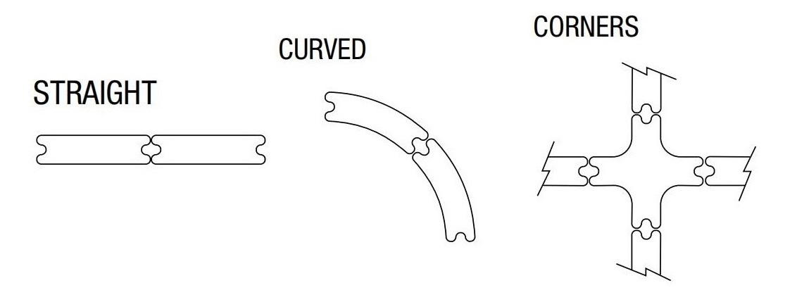
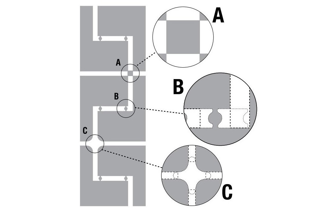
8.0Micro-Joints
Program-controlled spacing creates fine connections (approx. 0.2 mm) for easy part removal using a “shake-and-break” method.
Common micro-joint shapes include:
- Rectangular– for external corner joints
- Butterfly or fish-tail– for connecting the parts
- Trapezoidal– for one-sided attachment
Tools can be designed for efficient part separation according to disassembly needs.
Three common disassembly methods:
- Shake-and-Break: Close-spaced joints broken manually.
- Tab Tool: Large inner-corner spacing creates micro-joints.
- 4-Way Radius Tool: Simultaneously cuts four corners with joints for easy break-off.
9.0Notching
- 3-Way Corner Notching Toolis suitable for cutting angles from 15° to 150°.
- Fully guided tooling is recommended for tool stability.
- For sharp corner edges, a minimum radius of 0.25 mm is advised to reduce wear.
- Pre-punching small holes (elliptical or round) can relieve stress during bending and enhance joint strength.
- Custom notching tools with a “nose tip” design can be created.
10.0Cluster Punching
Cluster tooling is an efficient method to produce repeated holes or patterns in sheet metal. By increasing the number of holes per stroke, cluster punching reduces production time, lowers costs, and decreases machine wear. Various punch designs and cluster configurations are available to suit different applications.
Key Points:
Cluster punching maximizes efficiency by punching multiple holes simultaneously.
Tool wear increases punching force, so monitoring tool condition is important.
Punching Force Calculation:
The maximum recommended punching force should not exceed 75% of the press’s rated capacity. Use the following formula to estimate the required punching force:
Punching Force (tons / metric tons)
= Linear Length of Cut × Material Thickness × Shear Strength
-
Linear Length of Cut
= Hole Perimeter × Number of Punches in the Cluster -
Hole Perimeter
-
Round Hole = 3.14 × Diameter
-
Shaped Hole = Sum of the Side Lengths
-
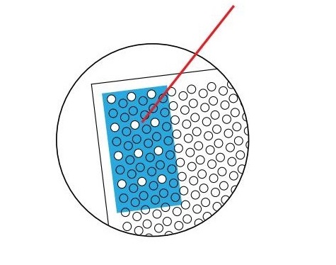
In the example, the punch (blue rectangle) is a cluster of 12 round holes, each 0.250 in (6.35 mm) in diameter. The cluster covers a total of 48 holes punched in sets of 12 holes × 4 hits. The material is mild steel with a thickness of 0.060 in (1.52 mm).
Punching Force Calculation (Round Holes)
| Unit | Hole Perimeter Calculation | × Punches | = Linear Length of Cut | × Thickness | × Shear Strength | = Punching Force |
|---|---|---|---|---|---|---|
| Inch | 3.14 × 0.250 = 0.785 in | × 12 | = 9.42 in | × 0.060 in | × 25 | = 14.1 tons |
| Metric | 3.14 × 6.35 = 19.94 mm | × 12 | = 239.26 mm | × 1.52 mm | × 0.345 | = 12.8 metric tons |
Punching Force Calculation (Square Holes)
| Unit | Hole Perimeter Calculation | × Punches | = Linear Length of Cut | × Thickness | × Shear Strength | = Punching Force |
|---|---|---|---|---|---|---|
| Inch | 4 × 0.250 = 1.00 in | × 12 | = 12.00 in | × 0.060 in | × 25 | = 18.0 tons |
| Metric | 4 × 6.35 = 25.40 mm | × 12 | = 304.80 mm | × 1.52 mm | × 0.345 | = **16.3 metric |
Cluster Punching (Continued)
Minimum punch size
When punching small diameter holes, it’s essential that tools are properly sharpened and well-maintained. Use the following punch-to-material thickness ratios as general guidelines to avoid tool failure or machine issues:
| Material | Standard Tooling Ratio | Fully Guided Tooling Ratio |
| Aluminum | 0.75 : 1 | 0.5 : 1 |
| Mild Steel | 1 : 1 | 0.75 : 1 |
| Stainless Steel | 2 : 1 | 1 : 1 |
Example (Material Thickness = .078″ / 2.0mm):
| Material | Smallest Punch (Standard) | Smallest Punch (Fully Guided) |
| Aluminum (.078 / 2.0 mm) | .059″ (1.5 mm) | .039″ (1.0 mm) |
| Mild Steel (.078 / 2.0 mm) | .078″ (2.0 mm) | .059″ (1.5 mm) |
| Stainless (.078 / 2.0 mm) | .157″ (4.0 mm) | .078″ (2.0 mm) |
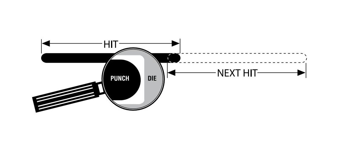
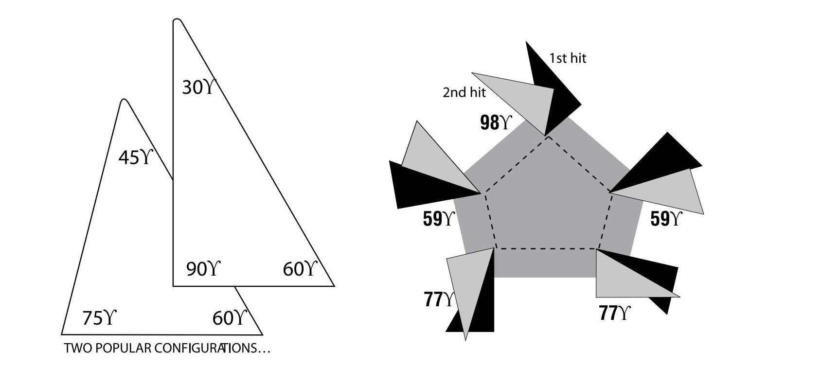
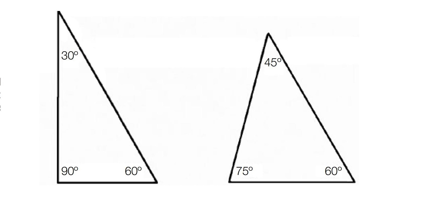
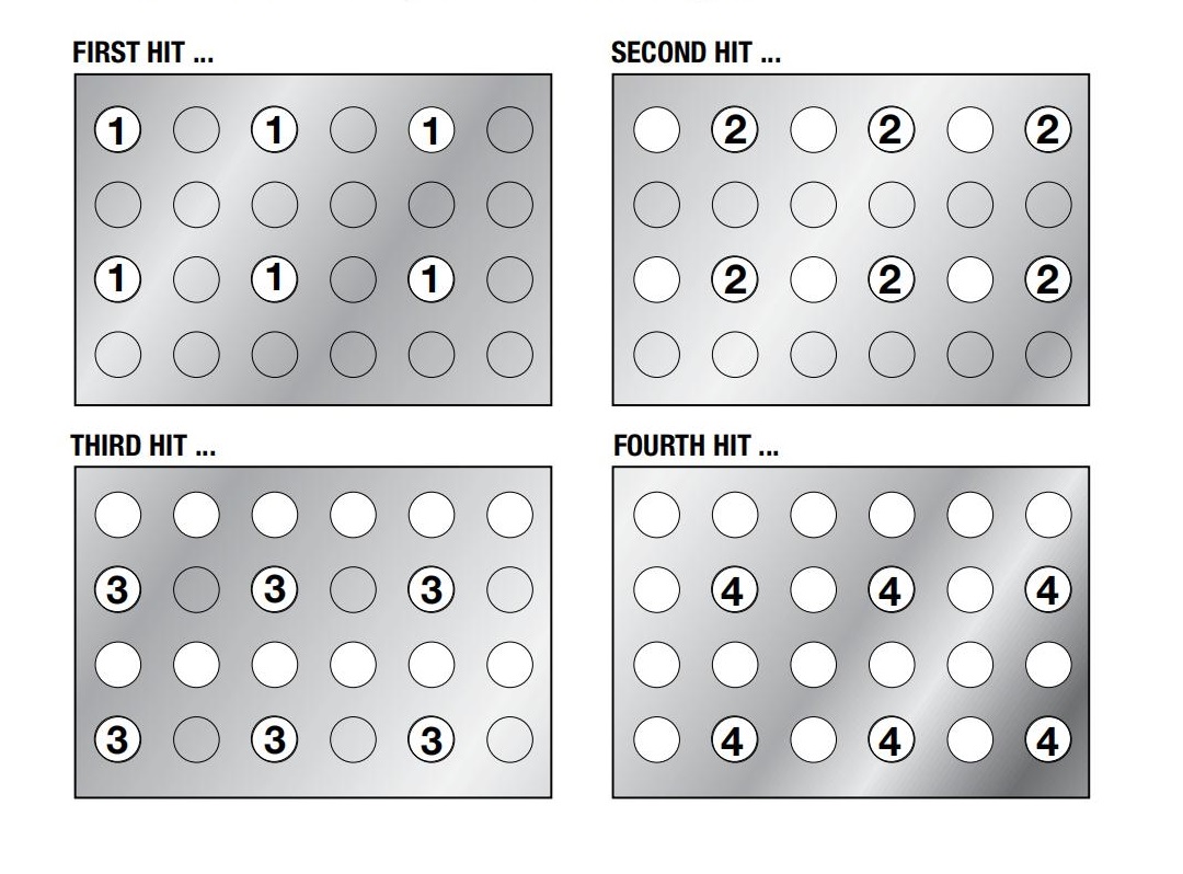
Hole Uniformity & Sheet Flatness
For better hole quality and flatter workpieces:
- Avoid punching adjacent holes in a single hit.
- Spread punches across multiple hits (e.g., first hit, second hit, fourth hit, etc.) to distribute force.
- Repeat as needed to complete the full pattern.
Use Fully-Guided Cluster Tools in Challenging Applications
Fully-guided cluster punches are recommended for:
- High-production environments
- Small-diameter punch points that require additional guidance
- Applications with fewer punch tips and reduced stripper contact
- Long runs and heavy-duty tasks
Coating for Extended Tool Life
- Increase the punch point lubricity
- Reduce wear
- Help maintain clean, consistent punching
Lubricate Cluster Punches
Use a high-quality lubricant (e.g., vanishing oil) to:
- Reduce heat build-up
- Prevent galling
11.0Punching Process Troubleshooting Quick Reference
| PROBLEM | POSSIBLE CAUSE | SOLUTION SUGGESTED |
| Excessive Burrs | Incorrect die clearance | Adjust to proper |
| Differing material hardness, although gage is the same |
Adjust clearance | |
| Dull punches and dies | Sharpen tooling | |
| Slug pile-up or packing | Check dies and clearance | |
| Increase punch penetration | ||
| Holder on station misaligned | Check alignment | |
| Poor Hole Quality | Dull punches and dies | Sharpen tooling |
| Improper clearance | Adjust to proper | |
| Die not properly seating | Check dies | |
| Holder or station out of alignment | Check alignment | |
| Punching thin material | Use guided tooling | |
| Punch Breakage | Inadequate die clearance | Adjust to proper |
| Crossed Shapes | Ensure tools are properly loaded in turret |
|
| Size of punch less than one material thickness |
Use guided tooling | |
| Punch Does Not Strip | Dull punches or dies | Sharpen tooling |
| Improper die clearance | Adjust to proper | |
| Difficult material | Adjust die clearance | |
| Weak spring | Replace spring | |
| Tool limitations exceeded | ||
| Galling | Lubricate tooling | |
| Punch Galling | Dull punch | Keep tools sharp |
| No lubrication | Lubricate work piece -Use Mate Eliminator pads (see page 17) |
|
| High hit rate | Adjust | |
| No coating | ||
| Inadequate die clearance | Increase die clearance | |
| Punch Sticking in Work Piece | Dull punch and/or die | Sharpen tools |
| Inadequate die clearance | Increase die clearance | |
| Galling on punch | Remove galling | |
| Inadequate lubrication | Lubricate work piece -Use Mate Eliminator pads (see page 17) |
|
| Weak spring | Increase stripping Replace stripping springs |
|
| Rapid Tool Wear | Inadequate die clearance | Increase die clearance |
| Punch overheating | Lubricate tools | |
| Poor sharpening practices | See Punch &Die Maintenance | |
| Nibbling | Alter programming | |
| Poor stripping | ||
| Poor tool alignment | Realign stations Level turret Replace tool holders |
|
| Material being punched (for example,stainless) |
||
| Sheet Accuracy | Worn work holders | Adjust or replace Replace gripping surfaces |
| Alignment problems | Realign table to press Inspect for worn turret bores Level turret |
|
| Slug Pulling | Magnetism in tools | Demagnetize |
| Small diameter holes** | See below | |
| **The most common condition(s)for slug pulling are:round holes.250 to .750(6.35 to 19)diameter in .039 to .078(1 to 2)thick material,with sharp tools,using optimum clearance,and minimum penetration on oiled material. The solutions suggested are to: ●Maximize die penetration Use Slug Free@dies ●Slug ejectors |
||
| Surface Cracks on Face of Punch | Tool improperly ground | Dress wheel and grind taking light cuts |
| Warpage of Work Piece | Dull tools | Sharpen punch and die (use coolant when sharpening) |
| Improper clearance | Increase or decrease as necessary | |
| No lubrication | Lubricate sheet | |
| Poor stripping | Increase stripping | |
| Programming | Reprogram punching sequence Bridge hit large openings |
|
12.0Summary
This article systematically introduces nine commonly used punching techniques, including Blanking, Corner Rounding, Small & Large Diameter Holes, Nibbling, Slitting, Micro-Joints, Notching, and Cluster Punching.
Each technique has its own specific process requirements and application scenarios. For example:
- Blanking focuses on die dimensions and edge sharpness.
- Corner rounding emphasizes improving productivity and reducing machine wear.
- Micro-joint technology facilitates easy part separation after punching.
By correctly selecting and optimizing these techniques, manufacturers can not only improve product quality but also extend tool life and reduce production costs, contributing to efficient and precise metal stamping processes.
13.0Frequently Asked Questions (FAQ)
Q1: What is blanking, and how does it differ from punching?
A1: Blanking cuts off the unwanted portion of sheet material, leaving the remaining material as the final product. In contrast, punching removes the desired portion from the sheet. In blanking, die size determines the final product dimensions.
Q2: What are the advantages of a 4-Way Corner Rounding Tool?
A2: The 4-way tool can punch all four corners at once, reducing the number of hits, minimizing machine wear, improving efficiency, and eliminating the need for index stations.
Q3: How do I determine the minimum punch size for small holes?
A3: Minimum punch size depends on material type and thickness. Refer to recommended punch diameter-to-thickness ratios. Using fully guided tooling allows for smaller holes with better accuracy.
Q4: What is nibbling, and when should it be used?
A4: Nibbling forms large or complex holes through a series of overlapping punches. It is ideal for non-standard shapes or large-diameter holes, producing smooth edges while reducing machine load.
Q5: What is the purpose of micro-joint technology?
A5: Micro-joints create tiny connections between punched parts and the base material, allowing parts to stay attached for easy handling, and later be separated manually without damage or misplacement.
Q6: How can I avoid material folding during slitting?
A6: Use elliptical punches with rounded dies to create smoother cutting paths and reduce lateral loads, preventing material from folding and improving cut quality.
Q7: How do I calculate punching force for cluster punching?
A7: Punching force (in tons) =
Total cutting length × Material thickness × Shear strength.
The maximum force should not exceed 75% of the press machine’s rated capacity.